diagram RENAULT SCENIC 2008 J84 / 2.G Passenger Comparment Connection Unit Workshop Manual
[x] Cancel search | Manufacturer: RENAULT, Model Year: 2008, Model line: SCENIC, Model: RENAULT SCENIC 2008 J84 / 2.GPages: 391
Page 2 of 391
PASSENGER COMPARTMENT CONNECTION UNIT
Fault finding - Introduction87B
87B-2
PASSENGER COMPARTMENT CONNECTION UNIT
Fault finding - Introduction87B
87B-2V9 MR-372-J84-87B000$043.mif
187B
UCH
Vdiag No.: 44, 48,
4C, 4D, 4F, 50PASSENGER COMPARTMENT CONNECTION UNIT
Fault finding - Introduction
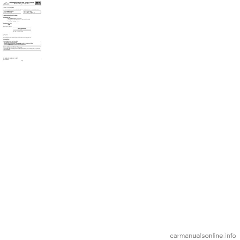
1. SCOPE OF THIS DOCUMENT
This document presents the fault finding procedure applicable to all computers with the following specifications:
2. PREREQUISITES FOR FAULT FINDING
Documentation type:
Fault finding procedures (this document):
–Assisted fault finding (integrated into the diagnostic tool), Dialogys.
Wiring Diagrams:
–Visu-Schéma (CD-ROM), paper.
Type of diagnostic tools:
–CLIP
Special tooling required:
3. REMINDERS
Procedure
To run fault finding on the vehicle computers, switch on the forced + after ignition feed.
Proceed as follows: Vehicle(s): Mégane II, Scénic II
Function concerned: UCHName of computer: UCH
Vdiag No.: 44, 48, 4C, 4D, 4F, 50.
Special tooling required
Multimeter
Elé. 1681 Universal bornier
Switch on the forced + after ignition feed:
–with the vehicle card in the card reader,
–press and hold start button (longer than 5 seconds) with start-up conditions not fulfilled,
–connect the diagnostic tool and perform the required operations.
Switching off the forced + after ignition feed:
Press the Start button twice briefly (less than 3 seconds).
ensure that the + after ignition feed has been cut off by checking that the computer indicator lights on the instrument
panel have gone out.
UCH_V44_PRELI /UCH_V48_PRELI/UCH_V4C_PRELI/
UCH_V4D_PRELI/UCH_V4F_PRELI/UCH_V50_PRELI
MR-372-J84-87B000$043.mif
Page 30 of 391
PASSENGER COMPARTMENT CONNECTION UNIT
Fault finding - System operation
87B
87B-30
PASSENGER COMPARTMENT CONNECTION UNIT
Fault finding - System operation
87B
87B-30V9 MR-372-J84-87B000$086.mif
UCH
Vdiag No.: 44, 48,
4C, 4D, 4F, 50
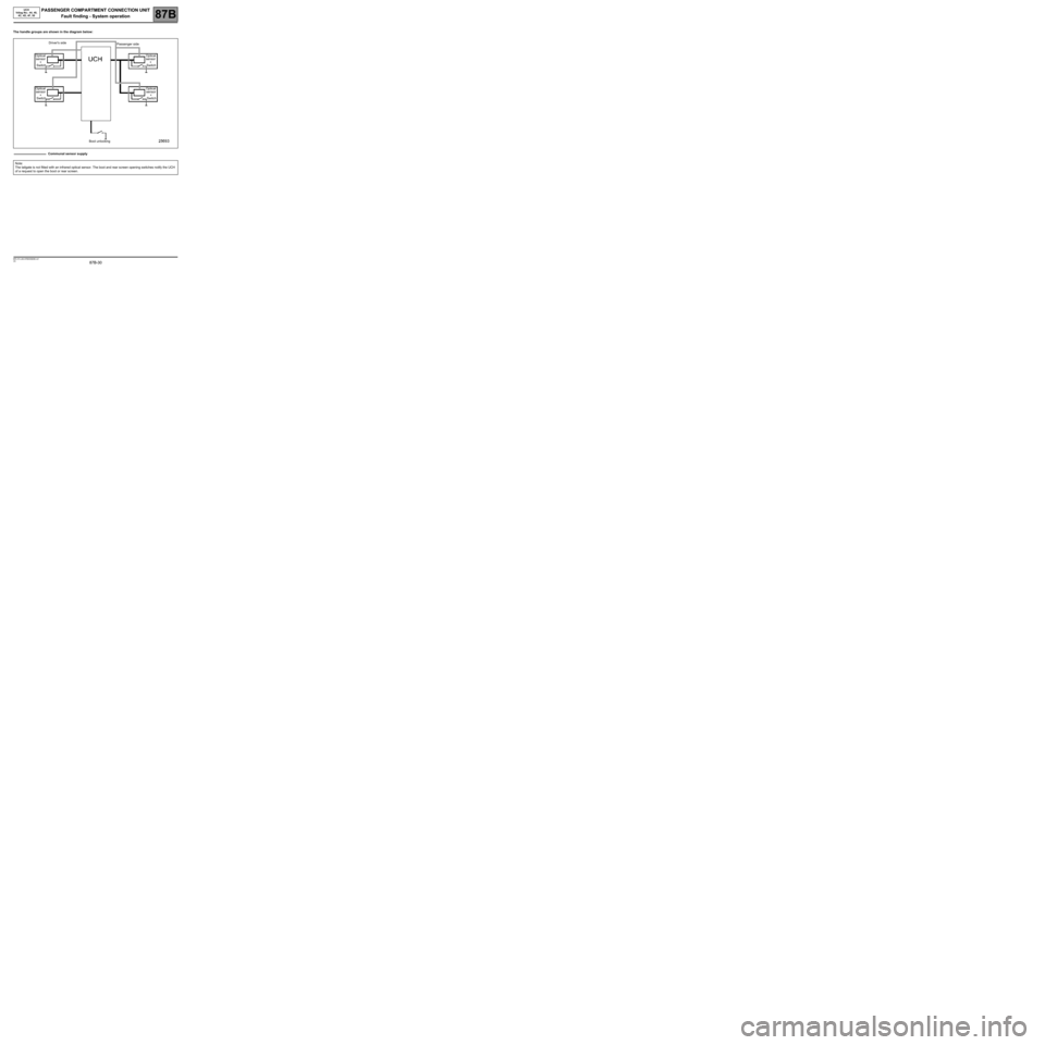
The handle groups are shown in the diagram below:
Communal sensor supply
Note:
The tailgate is not fitted with an infrared optical sensor. The boot and rear screen opening switches notify the UCH
of a request to open the boot or rear screen.
Optical
sensor
+
SwitchDriver's side
Passenger side
Optical
sensor
+
Switch
Optical
sensor
+
SwitchOptical
sensor
+
Switch
Boot unlocking
Page 31 of 391
PASSENGER COMPARTMENT CONNECTION UNIT
Fault finding - System operation
87B
87B-31
PASSENGER COMPARTMENT CONNECTION UNIT
Fault finding - System operation
87B
87B-31V9 MR-372-J84-87B000$086.mif
UCH
Vdiag No.: 44, 48,
4C, 4D, 4F, 50
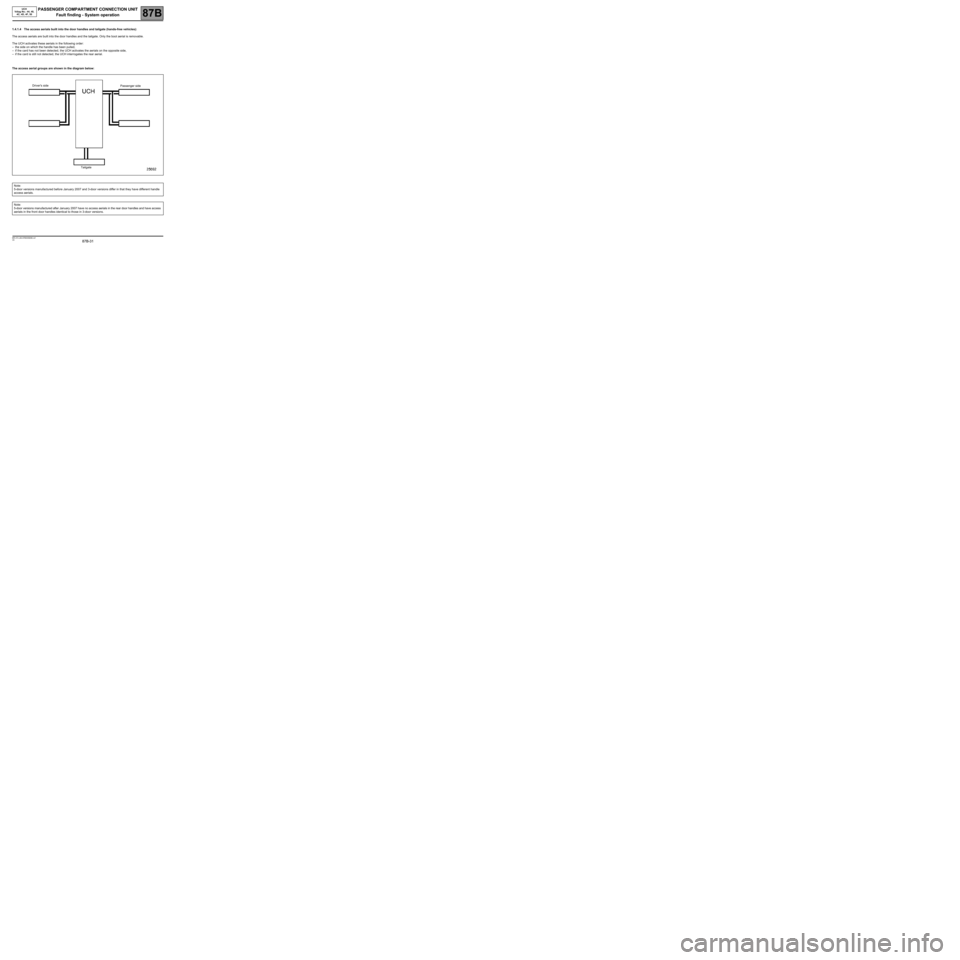
1.4.1.4 The access aerials built into the door handles and tailgate (hands-free vehicles):
The access aerials are built into the door handles and the tailgate. Only the boot aerial is removable.
The UCH activates these aerials in the following order:
–the side on which the handle has been pulled,
–if the card has not been detected, the UCH activates the aerials on the opposite side,
–if the card is still not detected, the UCH interrogates the rear aerial.
The access aerial groups are shown in the diagram below:
Note:
5-door versions manufactured before January 2007 and 3-door versions differ in that they have different handle
access aerials.
Note:
5-door versions manufactured after January 2007 have no access aerials in the rear door handles and have access
aerials in the front door handles identical to those in 3-door versions.
Driver's side
Passenger side
Tailgate
Page 32 of 391
PASSENGER COMPARTMENT CONNECTION UNIT
Fault finding - System operation
87B
87B-32
PASSENGER COMPARTMENT CONNECTION UNIT
Fault finding - System operation
87B
87B-32V9 MR-372-J84-87B000$086.mif
UCH
Vdiag No.: 44, 48,
4C, 4D, 4F, 50
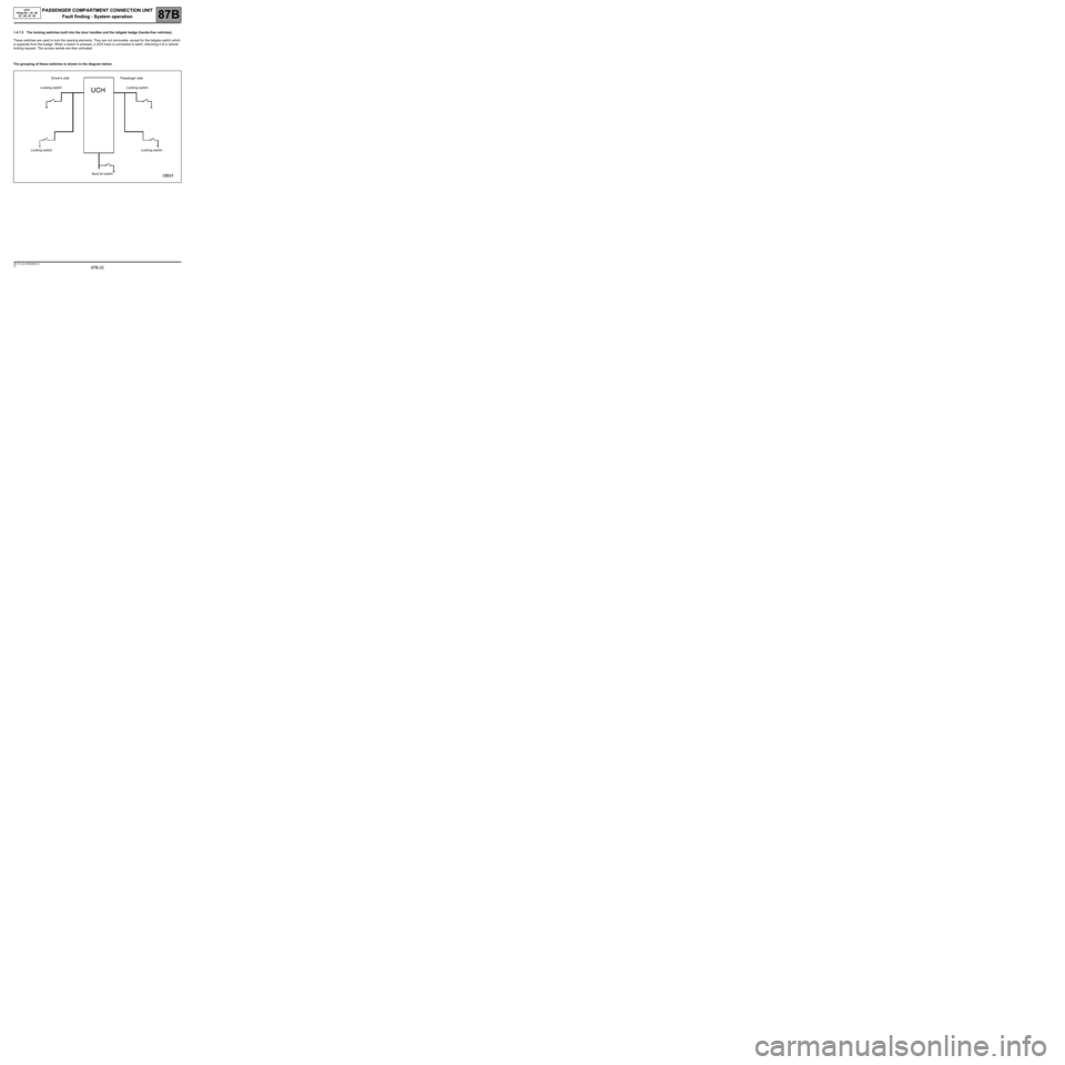
1.4.1.5 The locking switches built into the door handles and the tailgate badge (hands-free vehicles):
These switches are used to lock the opening elements. They are not removable, except for the tailgate switch which
is separate from the badge. When a switch is pressed, a UCH track is connected to earth, informing it of a vehicle
locking request. The access aerials are then activated.
The grouping of these switches is shown in the diagram below:
Driver's side Passenger side
Locking switch Locking switch
Locking switch Locking switch
Boot lid switch
Page 35 of 391
PASSENGER COMPARTMENT CONNECTION UNIT
Fault finding - System operation
87B
87B-35
PASSENGER COMPARTMENT CONNECTION UNIT
Fault finding - System operation
87B
87B-35V9 MR-372-J84-87B000$086.mif
UCH
Vdiag No.: 44, 48,
4C, 4D, 4F, 50
1.4.3 Main components of the STARTING sub-function:
The starting sub-function is based on the following main factors:
–The starting conditions being present.
–Passenger Compartment Control Unit (UCH).
–The automatic gearbox computer (if fitted on the vehicle).
–The Protection and Switching Unit.
1.4.3.1 Start button:
The start button transmits the driver's requests to start or stop the engine to the UCH.
1.4.3.2 The UCH:
The UCH ensures that the starting conditions are met, and that no other computer on the multiplex network is
inhibiting starting of the vehicle.
If the conditions are met, it requests control of the starter from the UPC.
1.4.3.3 The Protection and Switching Unit (UPC):
The Protection and Switching Unit activates the starter motor following a request from the UCH via the multiplex
network.
1.4.3.4 Neutral sensor (manual gearbox):
Informs the UCH of the position of the gearbox (neutral or gear engaged).
1.4.3.5 Clutch switch (manual gearbox):
Sends clutch pedal depressed signal (end of travel) to the UCH.
1.4.3.6 Brake switch:
Sends brake pedal depressed signal to the UCH.
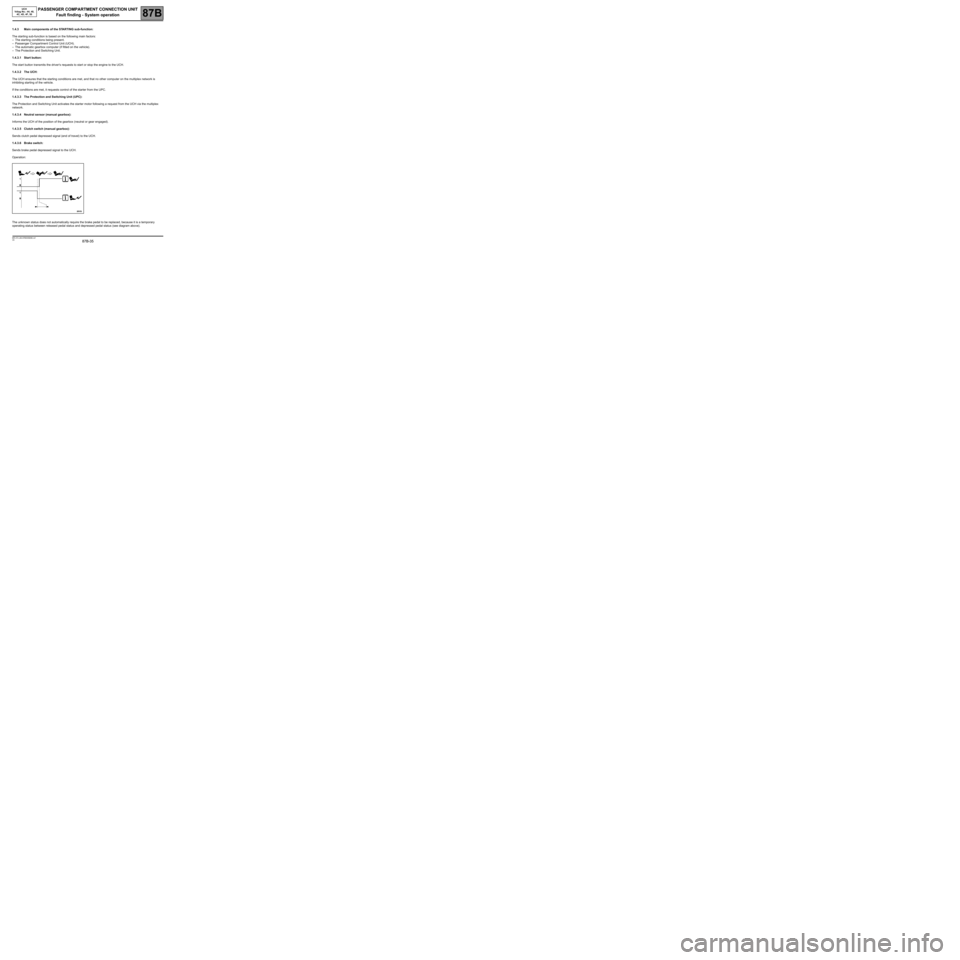
Operation:
The unknown status does not automatically require the brake pedal to be replaced, because it is a temporary
operating status between released pedal status and depressed pedal status (see diagram above).
Page 75 of 391
PASSENGER COMPARTMENT CONNECTION UNIT
Fault finding - Interpretation of faults
87B
87B-75
PASSENGER COMPARTMENT CONNECTION UNIT
Fault finding - Interpretation of faults
87B
87B-75V9 MR-372-J84-87B000$301.mif
UCH
Vdiag No.: 44, 48,
4C, 4D, 4F, 50
DF003
PRESENT
OR
STOREDCLUTCH SWITCH CIRCUIT
CO.1: Short circuit or open circuit to + 12 V
NOTESConditions for applying the fault finding procedure to a stored fault:
The fault appears after a road test at speed > 60 mph (100 km/h).
Use Wiring Diagrams Technical Note for MEGANE II or SCENIC II.
CO.1
NOTESNone.
Check the condition and connection of the clutch switch connector (tabs bent, broken, oxidised, etc.).
If the connector is faulty and if there is a repair method (see Technical Note 6015A, Repairing electrical wiring,
Wiring: Precautions for repair), repair the connector; otherwise, replace the wiring.
Check the condition and connection of the PE1 connector of the UCH (tabs bent, broken, oxidised, etc.).
If the connector is faulty and if there is a repair method (see Technical Note 6015A, Repairing electrical wiring,
Wiring: Precautions for repair), repair the connector; otherwise, replace the wiring.
Check the insulation and continuity against + 12 V of the following connection:
●Connection code 26X between components 645 and 675.
If the connection is faulty and if there is a repair procedure (see Technical Note 6015A, Electrical wiring repair,
Wiring: Precautions for repair), repair the wiring, otherwise replace the wiring.
Check for an earth on connection MAM of component 675.
If the connection is faulty and there is a repair procedure (see Technical Note 6015A, Electrical wiring repair,
Wiring: Precautions for repair), repair the connection, otherwise replace the wiring.
If the connection is OK and earth is present, replace the clutch switch.
If the fault is still present, contact the Techline.
AFTER REPAIRCarry out another fault finding check on the system.
Clear the stored faults.
Deal with any other faults.
UCH_V44_DF003 /UCH_V48_DF003/UCH_V4C_DF003/
UCH_V4D_DF003/UCH_V4F_DF003/UCH_V50_DF003
Page 79 of 391
PASSENGER COMPARTMENT CONNECTION UNIT
Fault finding - Interpretation of faults
87B
87B-79
PASSENGER COMPARTMENT CONNECTION UNIT
Fault finding - Interpretation of faults
87B
87B-79V9 MR-372-J84-87B000$301.mif
UCH
Vdiag No.: 44, 48,
4C, 4D, 4F, 50
DF010
PRESENT
OR
STORED
STEERING COLUMN SWITCH COMBINED CIRCUIT
1.DEF: The combined stalk is not connected or not correctly connected (stalk or UCH
side), not being supplied or has an internal electronic fault
2.DEF: Combined stalk lighting function connection to UCH in open circuit or internal
stalk fault
3.DEF: Combined stalk wiping function connection to UCH in open circuit or internal
stalk fault
4.DEF: Combined stalk direction indicator function connection to UCH in open circuit
or internal stalk fault
5.DEF: Combined stalk trip computer function connection to UCH in open circuit or
internal stalk fault
1.DEF
2.DEF
3.DEF
4.DEF
5.DEF
NOTESConditions for applying the fault finding procedure to a
stored fault:
If the fault becomes present after an action on the stalk, then
carry out this fault finding procedure.
Use Wiring Diagrams Technical Note for MEGANE II or
SCENIC II.
Check the condition and connection of the PE2 connector of the UCH (tabs bent, broken, oxidised).
If the connector is faulty and if there is a repair method (see Technical Note 6015A, Repairing electrical wiring,
Wiring: Precautions for repair), repair the connector; otherwise, replace the wiring.
Check the condition and connection of the steering column control connector (tabs bent, broken, oxidised, etc.).
If the connector is faulty and if there is a repair method (see Technical Note 6015A, Repairing electrical wiring,
Wiring: Precautions for repair), repair the connector; otherwise, replace the wiring.
Check the insulation and continuity of the following connections:
●Connection code 14 1B,
●Connection code 14 1K,
●Connection ode 14 1C,
●Connection code 141L,
●Connection code 14 1D,
●Connection code 14 1M,
●Connection code 14 1G,
●Connection code 14 1N,
●Connection code 14 1H,
●Connection code 14 1P.
Between components 645 and 1519.
If the connection or connections are faulty and there is a repair procedure (see Technical Note 6015A, Electrical
wiring repair, Wiring: Precautions for repair), repair the wiring, otherwise replace it.
If these connections are sound, contact the Techline.
AFTER REPAIRCarry out another fault finding check on the system.
Clear the stored faults.
Deal with any other faults.
UCH_V44_DF010 /UCH_V48_DF010/UCH_V4C_DF010/
UCH_V4D_DF010/UCH_V4F_DF010/UCH_V50_DF010
Page 80 of 391
PASSENGER COMPARTMENT CONNECTION UNIT
Fault finding - Interpretation of faults
87B
87B-80
PASSENGER COMPARTMENT CONNECTION UNIT
Fault finding - Interpretation of faults
87B
87B-80V9 MR-372-J84-87B000$301.mif
UCH
Vdiag No.: 44, 48,
4C, 4D, 4F, 50
DF011
PRESENT
OR
STOREDRAIN/LIGHT SENSOR CIRCUIT
1.DEF: Communication disrupted
2.DEF: Internal electronic fault
NOTESConditions for applying the fault finding procedure to a stored fault:
Run the automatic wiper system and automatic light illumination system, then cover the
sensor and/or place water on it.
If the fault appears, carry out this fault finding procedure.
Use Wiring Diagrams Technical Note for MEGANE II or SCENIC II.
1.DEF
NOTESNone.
For vehicles which were manufactured after June 2005, check the condition and connection of the sensor supply
7.5A fuse located on the Protection and Switching Unit.
Replace it if necessary.
Check the condition and connection of the sensor connector (bent, oxidised, broken tabs etc.).
If the connector is faulty and there is a repair procedure (see Technical Note 6015A, Electrical wiring repair,
Wiring: Precautions for repair), repair the connector, otherwise replace the wiring.
Check for an earth on connection MAM of component 1415.
If the connector is faulty and if there is a repair method (see Technical Note 6015A, Repairing electrical wiring,
Wiring: Precautions for repair), repair the connector; otherwise, replace the wiring.
Check for + 12 V, BPT connection of component 1415 (timed + 12 V before ignition feed if the vehicle was
manufactured after June 2005). If the connection is faulty and if there is a repair procedure (see Technical Note
6015A, Electrical wiring repair, Wiring: Precautions for repair), repair the wiring, otherwise replace the wiring.
Ensure the continuity and the insulation of the following connection:
●Connection code BPT between components 645 and 1415.
If the connection is faulty and if there is a repair procedure (see Technical Note 6015A, Electrical wiring repair,
Wiring: Precautions for repair), repair the wiring, otherwise replace the wiring.
Check for any intermediate connectors using the vehicle wiring diagram and repair if necessary.
AFTER REPAIRCarry out another fault finding check on the system.
Clear the stored faults.
Deal with any other faults.
UCH_V44_DF011/UCH_V48_DF011/UCH_V4C_DF011/
UCH_V4D_DF011/UCH_V4F_DF011 /UCH_V50_DF011
Page 82 of 391
PASSENGER COMPARTMENT CONNECTION UNIT
Fault finding - Interpretation of faults
87B
87B-82
PASSENGER COMPARTMENT CONNECTION UNIT
Fault finding - Interpretation of faults
87B
87B-82V9 MR-372-J84-87B000$301.mif
UCH
Vdiag No.: 44, 48,
4C, 4D, 4F, 50
DF012
PRESENT
OR
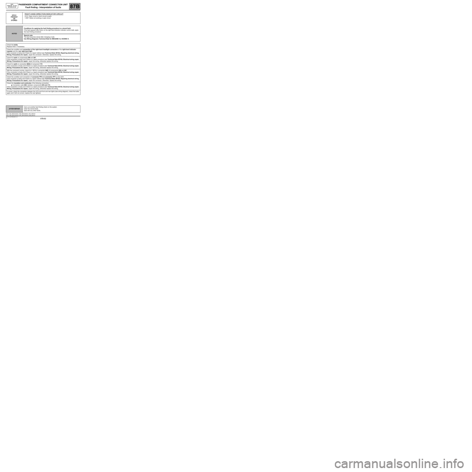
STOREDRIGHT-HAND DIRECTION INDICATOR CIRCUIT
CO.0: Open circuit or short circuit to earth
1.DEF: Bulbs not working or open circuit
NOTESConditions for applying the fault finding procedure to a stored fault:
If the fault appears after action on the right-hand direction indicator control stalk, apply
this fault finding procedure.
Special note:
The fault becomes stored after changing a bulb.
Use Wiring Diagrams Technical Note for MEGANE II or SCENIC II.
Check the bulbs.
Replace them, if necessary.
Check the condition and connection of the right-hand headlight connectors of the right-hand indicator
repeater and the rear right-hand light.
If the connector is faulty and if there is a repair method (see Technical Note 6015A, Repairing electrical wiring,
Wiring: Precautions for repair), repair the connector; otherwise, replace the wiring.
Check for earth on components 226 and 267.
If the connection is faulty and if there is a repair procedure (see Technical Note 6015A, Electrical wiring repair,
Wiring: Precautions for repair), repair the wiring, otherwise replace the wiring.
Check for earth on connection MAQ of component 172.
If the connection is faulty and if there is a repair procedure (see Technical Note 6015A, Electrical wiring repair,
Wiring: Precautions for repair), repair the wiring, otherwise replace the wiring.
With the command running, check for + 12 V on connection 64D of components 226 and 267.
If the connection is faulty and if there is a repair procedure (see Technical Note 6015A, Electrical wiring repair,
Wiring: Precautions for repair), repair the wiring, otherwise replace the wiring.
Check the condition and connection of connector PP3 and connector PP1 on the UCH.
If the connector is faulty and if there is a repair method (see Technical Note 6015A, Repairing electrical wiring,
Wiring: Precautions for repair), repair the connector; otherwise, replace the wiring.
Check the insulation and continuity of the following connection:
●Connection code 64D, between components 645 and 172.
If the connection is faulty and if there is a repair procedure (see Technical Note 6015A, Electrical wiring repair,
Wiring: Precautions for repair), repair the wiring, otherwise replace the wiring.
If correct, check the connection between the UCH and front and rear lights (see wiring diagram), check the bulbs
again and if still not correct, replace the rear lights(s).
AFTER REPAIRCarry out another fault finding check on the system.
Clear the stored faults.
Deal with any other faults.
UCH_V44_DF012 /UCH_V48_DF012/UCH_V4C_DF012/
UCH_V4D_DF012/UCH_V4F_DF012/UCH_V50_DF012
Page 83 of 391
PASSENGER COMPARTMENT CONNECTION UNIT
Fault finding - Interpretation of faults
87B
87B-83
PASSENGER COMPARTMENT CONNECTION UNIT
Fault finding - Interpretation of faults
87B
87B-83V9 MR-372-J84-87B000$301.mif
UCH
Vdiag No.: 44, 48,
4C, 4D, 4F, 50
DF013
PRESENT
OR
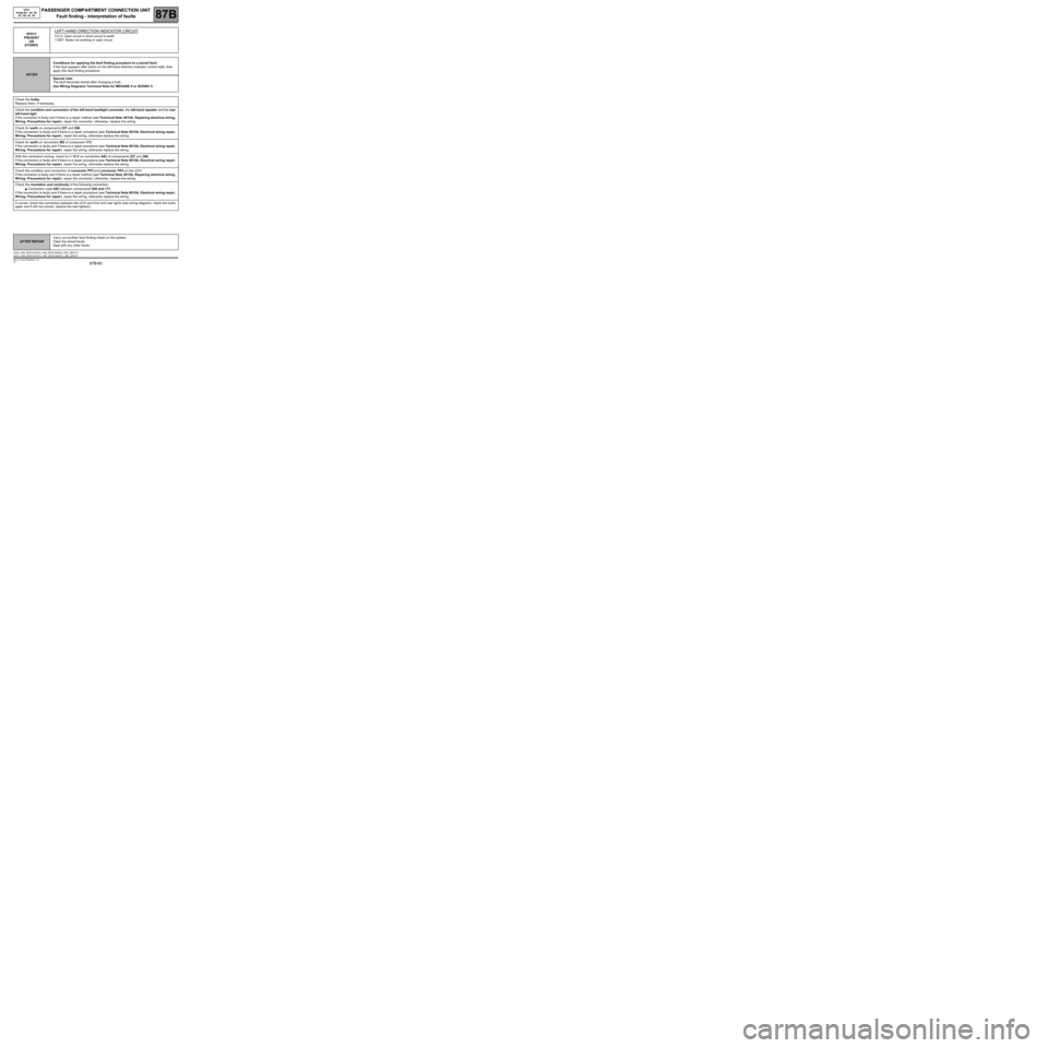
STOREDLEFT-HAND DIRECTION INDICATOR CIRCUIT
CO.0: Open circuit or short circuit to earth
1.DEF: Bulbs not working or open circuit
NOTESConditions for applying the fault finding procedure to a stored fault:
If the fault appears after action on the left-hand direction indicator control stalk, then
apply this fault finding procedure.
Special note:
The fault becomes stored after changing a bulb.
Use Wiring Diagrams Technical Note for MEGANE II or SCENIC II.
Check the bulbs.
Replace them, if necessary.
Check the condition and connection of the left-hand headlight connector, the left-hand repeater and the rear
left-hand light.
If the connector is faulty and if there is a repair method (see Technical Note 6015A, Repairing electrical wiring,
Wiring: Precautions for repair), repair the connector; otherwise, replace the wiring.
Check for earth on components 227 and 268.
If the connection is faulty and if there is a repair procedure (see Technical Note 6015A, Electrical wiring repair,
Wiring: Precautions for repair), repair the wiring, otherwise replace the wiring.
Check for earth on connection MZ of component 173.
If the connection is faulty and if there is a repair procedure (see Technical Note 6015A, Electrical wiring repair,
Wiring: Precautions for repair), repair the wiring, otherwise replace the wiring.
With the command running, check for + 12 V on connection 64C of components 227 and 268.
If the connection is faulty and if there is a repair procedure (see Technical Note 6015A, Electrical wiring repair,
Wiring: Precautions for repair), repair the wiring, otherwise replace the wiring.
Check the condition and connection of connector PP3 and connector PP2 on the UCH.
If the connector is faulty and if there is a repair method (see Technical Note 6015A, Repairing electrical wiring,
Wiring: Precautions for repair), repair the connector; otherwise, replace the wiring.
Check the insulation and continuity of the following connection:
●Connection code 64C between components 645 and 173.
If the connection is faulty and if there is a repair procedure (see Technical Note 6015A, Electrical wiring repair,
Wiring: Precautions for repair), repair the wiring, otherwise replace the wiring.
If correct, check the connection between the UCH and front and rear lights (see wiring diagram), check the bulbs
again and if still not correct, replace the rear lights(s).
AFTER REPAIRCarry out another fault finding check on the system.
Clear the stored faults.
Deal with any other faults.
UCH_V44_DF013 /UCH_V48_DF013/UCH_V4C_DF013/
UCH_V4D_DF013/UCH_V4F_DF013/UCH_V50_DF013