check engine RENAULT SCENIC 2011 J95 / 3.G Engine And Peripherals EDC16C36 Workshop Manual
[x] Cancel search | Manufacturer: RENAULT, Model Year: 2011, Model line: SCENIC, Model: RENAULT SCENIC 2011 J95 / 3.GPages: 431, PDF Size: 2.03 MB
Page 139 of 431
13B-139
AFTER REPAIRDeal with any other faults. Clear the fault memory.
Switch off the ignition until the end of the power-latch phase, and carry out a road test
followed by a check using the diagnostic tool.
V9 MR-372-J84-13B450$103.mif
DIESEL INJECTION
Fault finding – Interpretation of faults13B
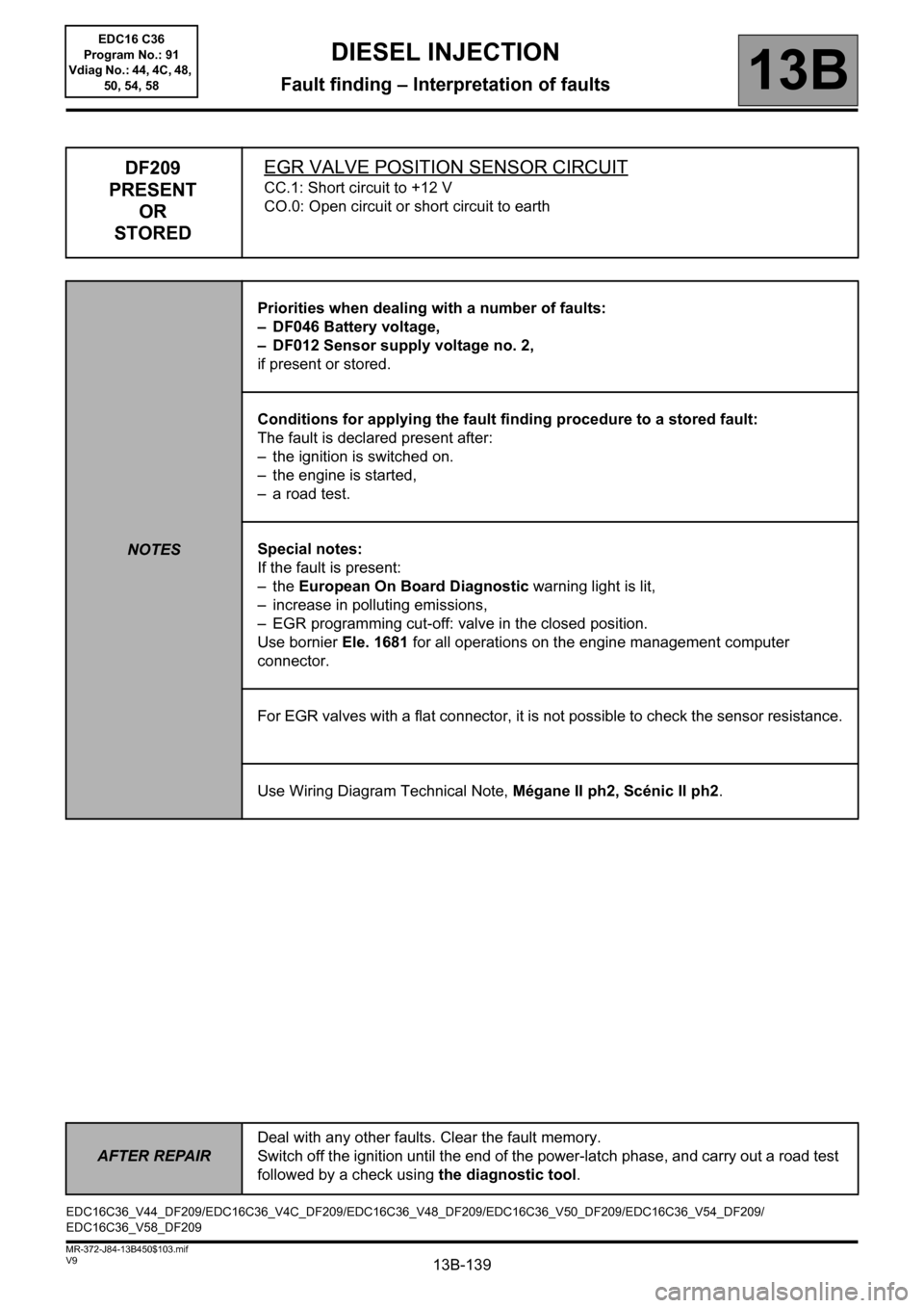
DF209
PRESENT
OR
STOREDEGR VALVE POSITION SENSOR CIRCUIT
CC.1: Short circuit to +12 V
CO.0: Open circuit or short circuit to earth
NOTESPriorities when dealing with a number of faults:
– DF046 Battery voltage,
– DF012 Sensor supply voltage no. 2,
if present or stored.
Conditions for applying the fault finding procedure to a stored fault:
The fault is declared present after:
– the ignition is switched on.
– the engine is started,
– a road test.
Special notes:
If the fault is present:
–the European On Board Diagnostic warning light is lit,
– increase in polluting emissions,
– EGR programming cut-off: valve in the closed position.
Use bornier Ele. 1681 for all operations on the engine management computer
connector.
For EGR valves with a flat connector, it is not possible to check the sensor resistance.
Use Wiring Diagram Technical Note, Mégane II ph2, Scénic II ph2.
EDC16C36_V44_DF209/EDC16C36_V4C_DF209/EDC16C36_V48_DF209/EDC16C36_V50_DF209/EDC16C36_V54_DF209/
EDC16C36_V58_DF209EDC16 C36
Program No.: 91
Vdiag No.: 44, 4C, 48,
50, 54, 58
Page 140 of 431

13B-140
AFTER REPAIRDeal with any other faults. Clear the fault memory.
Switch off the ignition until the end of the power-latch phase, and carry out a road test
followed by a check using the diagnostic tool.
V9 MR-372-J84-13B450$103.mif
DIESEL INJECTION
Fault finding – Interpretation of faults13B
DF209
CONTINUED 1
CC.1NOTESNone.
Check the condition of the connector of the EGR valve (see Wiring Diagram Technical Note, Mégane II ph2,
Scénic II ph2, Code organe1460).
Check the condition of the engine management computer connector (see Wiring Diagram Technical Note,
Mégane II ph2, Scénic II ph2, component code 120).
If the connector or connectors are faulty and if there is a repair procedure (see Technical Note 6015A, Repairing
electrical wiring, Wiring: Precautions for repair), repair the connector, otherwise replace the wiring.
Check the continuity and insulation against +12 V and +5 V on the following connections:
– Connection code 3GC between components 1460 and 120.
– Connection code 3EL between components 1460 and 120.
– Connection code 3JM between components 1460 and 120.
Check the insulation between the following connections:
– Connection code 3GC between components 1460 and 120.
– Connection code 3VP between components 1460 and 120.
– Connection code 3EL between components 1460 and 120.
If there is a repair method (see Technical Note 6015A, Repairing electrical wiring, Wiring: Precautions for
repair), repair the wiring, otherwise replace it.
EGR valve with a square connector:
Measure the resistances of the EGR valve between the following connections:
(sensor supply and sensor earth)
– Connection code 3GC of component 1460.
– Connection code 3JM of component 1460.
Replace the valve if the resistances are not between: 3.9 kΩ < X < 9.1 kΩ.
EGR valve with a flat connector:
Replace the EGR valve.
When replacing the EGR valve, run command SC036 Reinitialise programming and select EGR valve to
reinitialise the EGR valve offsets (see Replacement of components
).
If the fault is still present, contact the Techline.
EDC16 C36
Program No.: 91
Vdiag No.: 44, 4C, 48,
50, 54, 58
Page 141 of 431

13B-141
AFTER REPAIRDeal with any other faults. Clear the fault memory.
Switch off the ignition until the end of the power-latch phase, and carry out a road test
followed by a check using the diagnostic tool.
V9 MR-372-J84-13B450$103.mif
DIESEL INJECTION
Fault finding – Interpretation of faults13B
DF209
CONTINUED 2
CO.0NOTESNone.
Check the condition of the connector of the EGR valve (see Wiring Diagram Technical Note, Mégane II ph2,
Scénic II ph2, Component code 1460).
Check the condition of the engine management computer connector (see Wiring Diagram Technical Note,
Mégane II ph2, Scénic II ph2, component code 120).
If the connector or connectors are faulty and if there is a repair procedure (see Technical Note 6015A, Repairing
electrical wiring, Wiring: Precautions for repair), repair the connector, otherwise replace the wiring.
Check the continuity and insulation from earth of the following connections:
– Connection code 3GC between components 1460 and 120.
– Connection code 3EL between components 1460 and 120.
– Connection code 3JM between components 1460 and 120.
Check the insulation between the following connections:
– Connection code 3GC between components 1460 and 120.
– Connection code 3EL between components 1460 and 120.
– Connection code 3JM between components 1460 and 120.
– Connection code 3VQ between components 1460 and 120.
If there is a repair method (see Technical Note 6015A, Repairing electrical wiring, Wiring: Precautions for
repair), repair the wiring, otherwise replace it.
Measure the resistance of the EGR valve between the following connections:
(sensor supply and sensor earth)
– Connection code 3GC of component 1460.
– Connection code 3JM of component 1460.
Replace the valve if the resistances are not between: 3.9 kΩ < X < 9.1 kΩ.
When replacing the EGR valve, run command SC036 Reinitialise programming and select EGR valve
to
reinitialise the EGR valve offsets (see Replacement of components).
If the fault is still present, contact the Techline.
EDC16 C36
Program No.: 91
Vdiag No.: 44, 4C, 48,
50, 54, 58
Page 142 of 431
13B-142
AFTER REPAIRDeal with any other faults. Clear the fault memory.
Switch off the ignition until the end of the power-latch phase, and carry out a road test
followed by a check using the diagnostic tool.
V9 MR-372-J84-13B450$103.mif
DIESEL INJECTION
Fault finding – Interpretation of faults13B
* The immobiliser warning light will flash a few seconds after the ignition is switched off.
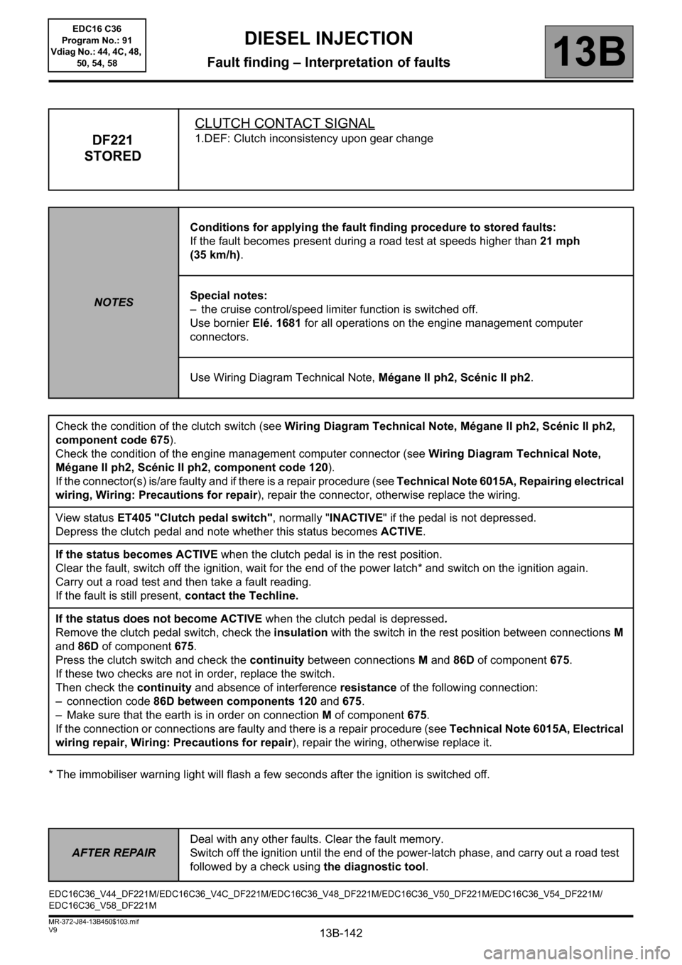
DF221
STOREDCLUTCH CONTACT SIGNAL1.DEF: Clutch inconsistency upon gear change
NOTESConditions for applying the fault finding procedure to stored faults:
If the fault becomes present during a road test at speeds higher than 21 mph
(35 km/h).
Special notes:
– the cruise control/speed limiter function is switched off.
Use bornier Elé. 1681 for all operations on the engine management computer
connectors.
Use Wiring Diagram Technical Note, Mégane II ph2, Scénic II ph2.
Check the condition of the clutch switch (see Wiring Diagram Technical Note, Mégane II ph2, Scénic II ph2,
component code 675).
Check the condition of the engine management computer connector (see Wiring Diagram Technical Note,
Mégane II ph2, Scénic II ph2, component code 120).
If the connector(s) is/are faulty and if there is a repair procedure (see Technical Note 6015A, Repairing electrical
wiring, Wiring: Precautions for repair), repair the connector, otherwise replace the wiring.
View status ET405 "Clutch pedal switch", normally "INACTIVE" if the pedal is not depressed.
Depress the clutch pedal and note whether this status becomes ACTIVE.
If the status becomes ACTIVE when the clutch pedal is in the rest position.
Clear the fault, switch off the ignition, wait for the end of the power latch* and switch on the ignition again.
Carry out a road test and then take a fault reading.
If the fault is still present, contact the Techline.
If the status does not become ACTIVE when the clutch pedal is depressed.
Remove the clutch pedal switch, check the insulation with the switch in the rest position between connectionsM
and 86D of component675.
Press the clutch switch and check the continuity between connectionsM and 86D of component675.
If these two checks are not in order, replace the switch.
Then check the continuity and absence of interference resistance of the following connection:
– connection code 86D between components 120 and 675.
– Make sure that the earth is in order on connection M of component 675.
If the connection or connections are faulty and there is a repair procedure (see Technical Note 6015A, Electrical
wiring repair, Wiring: Precautions for repair), repair the wiring, otherwise replace it.
EDC16C36_V44_DF221M/EDC16C36_V4C_DF221M/EDC16C36_V48_DF221M/EDC16C36_V50_DF221M/EDC16C36_V54_DF221M/
EDC16C36_V58_DF221MEDC16 C36
Program No.: 91
Vdiag No.: 44, 4C, 48,
50, 54, 58
Page 143 of 431
13B-143
AFTER REPAIRDeal with any other faults. Clear the fault memory.
Switch off the ignition until the end of the power-latch phase, and carry out a road test
followed by a check using the diagnostic tool.
V9 MR-372-J84-13B450$103.mif
DIESEL INJECTION
Fault finding – Interpretation of faults13B
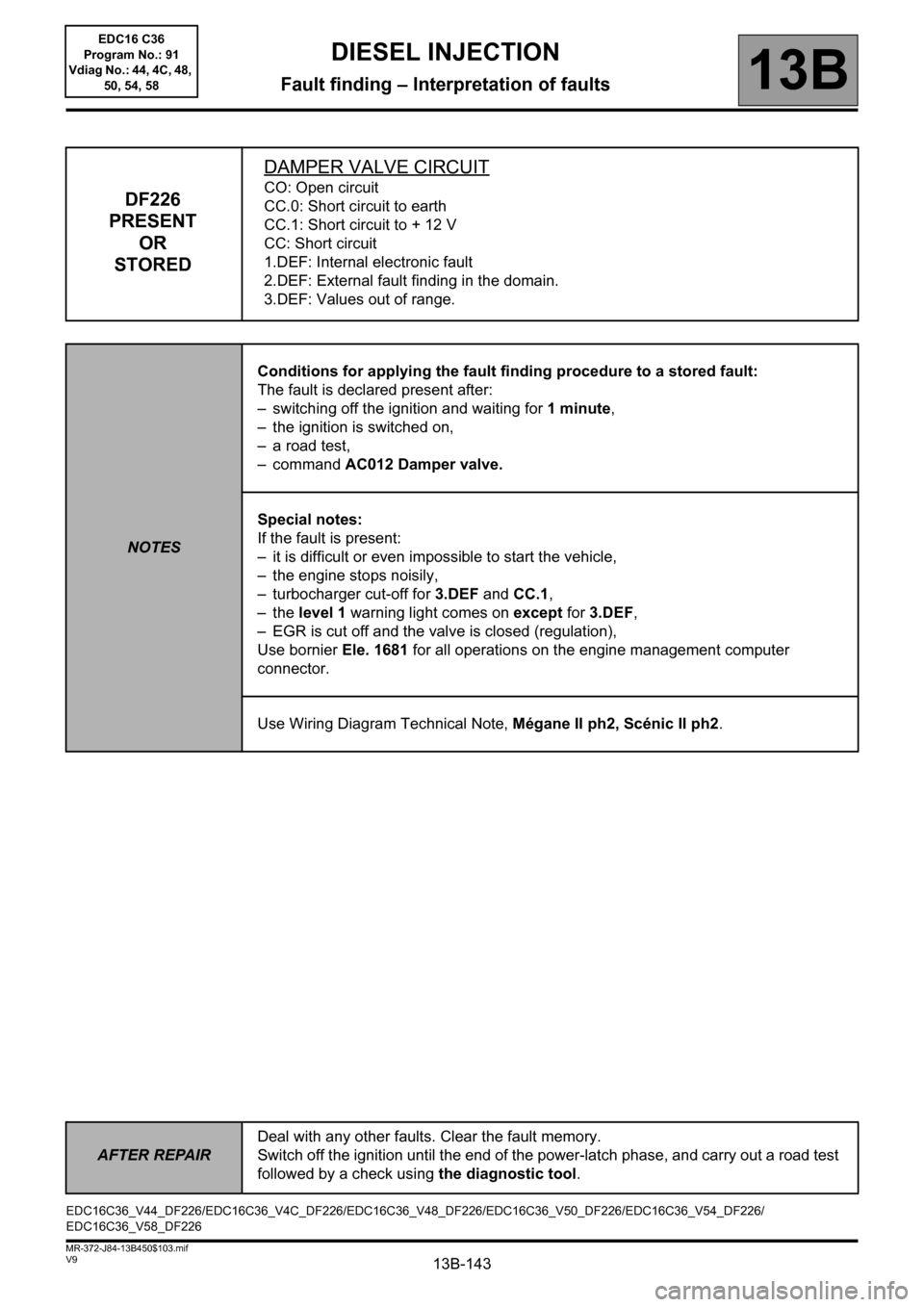
DF226
PRESENT
OR
STOREDDAMPER VALVE CIRCUITCO: Open circuit
CC.0: Short circuit to earth
CC.1: Short circuit to + 12 V
CC: Short circuit
1.DEF: Internal electronic fault
2.DEF: External fault finding in the domain.
3.DEF: Values out of range.
NOTESConditions for applying the fault finding procedure to a stored fault:
The fault is declared present after:
– switching off the ignition and waiting for 1minute,
– the ignition is switched on,
– a road test,
– command AC012 Damper valve.
Special notes:
If the fault is present:
– it is difficult or even impossible to start the vehicle,
– the engine stops noisily,
– turbocharger cut-off for 3.DEF and CC.1,
–the level 1 warning light comes on except for 3.DEF,
– EGR is cut off and the valve is closed (regulation),
Use bornier Ele. 1681 for all operations on the engine management computer
connector.
Use Wiring Diagram Technical Note, Mégane II ph2, Scénic II ph2.
EDC16C36_V44_DF226/EDC16C36_V4C_DF226/EDC16C36_V48_DF226/EDC16C36_V50_DF226/EDC16C36_V54_DF226/
EDC16C36_V58_DF226EDC16 C36
Program No.: 91
Vdiag No.: 44, 4C, 48,
50, 54, 58
Page 144 of 431

13B-144
AFTER REPAIRDeal with any other faults. Clear the fault memory.
Switch off the ignition until the end of the power-latch phase, and carry out a road test
followed by a check using the diagnostic tool.
V9 MR-372-J84-13B450$103.mif
DIESEL INJECTION
Fault finding – Interpretation of faults13B
DF226
CONTINUED 1
CC
CC.1NOTESAfter any operation on the damper valve, run SC036
Reinitialise programming (see Interpretation of
commands).
Check the condition of the damper valve (see Wiring Diagram Technical Note, Mégane II ph2, Scénic II ph2,
component code 1461).
Check the condition of the engine management computer connector (see Wiring Diagram Technical Note,
Mégane II ph2, Scénic II ph2, component code 120).
If the connectors are faulty and if there is a repair procedure (see Technical Note 6015A, Repairing electrical
wiring, Wiring: Precautions for repair), repair the connector, otherwise replace the wiring.
Check the insulation from + 12 V of the following connections:
– Connection code NT between components 1461 and NT.
– Connection code 3VM between components 1461 and 120.
– Connection code 3VN between components 1461 and 120.
Check the continuity and insulation between the following connections:
– Connection code NT between components 1461 and NT.
– Connection code 3VM between components 1461 and 120.
– Connection code 3VN between components 1461 and 120.
– Connection code 3FB between components 1461 and 983.
If there is a repair method (see Technical Note 6015A, Repairing electrical wiring, Wiring: Precautions for
repair), repair the wiring, otherwise replace it.
If the fault is still present, contact the Techline.
EDC16 C36
Program No.: 91
Vdiag No.: 44, 4C, 48,
50, 54, 58
Page 145 of 431

13B-145
AFTER REPAIRDeal with any other faults. Clear the fault memory.
Switch off the ignition until the end of the power-latch phase, and carry out a road test
followed by a check using the diagnostic tool.
V9 MR-372-J84-13B450$103.mif
DIESEL INJECTION
Fault finding – Interpretation of faults13B
DF226
CONTINUED 2
CC.0
CONOTESAfter any operation on the damper valve, run SC036
Reinitialise programming (see Interpretation of
commands).
Check the condition of the damper valve connector (see Wiring Diagram Technical Note, Mégane II ph2,
Scénic II ph2, component code 1461).
Check the condition of the engine management computer connector (see Wiring Diagram Technical Note,
Mégane II ph2, Scénic II ph2, component code 120).
If the connectors are faulty and if there is a repair procedure (see Technical Note 6015A, Repairing electrical
wiring, Wiring: Precautions for repair), repair the connector, otherwise replace the wiring.
Check the continuity and insulation against earth and between the following connections:
– Connection code NT between components 1461 and NT.
– Connection code 3VM between components 1461 and 120.
– Connection code 3VN between components 1461 and 120.
– Connection code 3FB between components 1461 and 983.
If there is a repair method (see Technical Note 6015A, Repairing electrical wiring, Wiring: Precautions for
repair), repair the wiring, otherwise replace it.
If the fault is still present, contact the Techline
EDC16 C36
Program No.: 91
Vdiag No.: 44, 4C, 48,
50, 54, 58
Page 146 of 431
13B-146
AFTER REPAIRDeal with any other faults. Clear the fault memory.
Switch off the ignition until the end of the power-latch phase, and carry out a road test
followed by a check using the diagnostic tool.
V9 MR-372-J84-13B450$103.mif
DIESEL INJECTION
Fault finding – Interpretation of faults13B
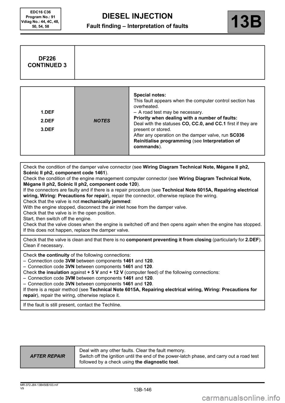
DF226
CONTINUED 3
1.DEF
2.DEF
3.DEF
NOTESSpecial notes:
This fault appears when the computer control section has
overheated.
– A road test may be necessary.
Priority when dealing with a number of faults:
Deal with the statuses CO, CC.0, and CC.1 first if they are
present or stored.
After any operation on the damper valve, run SC036
Reinitialise programming (see Interpretation of
commands).
Check the condition of the damper valve connector (see Wiring Diagram Technical Note, Mégane II ph2,
Scénic II ph2, component code 1461).
Check the condition of the engine management computer connector (see Wiring Diagram Technical Note,
Mégane II ph2, Scénic II ph2, component code 120).
If the connectors are faulty and if there is a repair procedure (see Technical Note 6015A, Repairing electrical
wiring, Wiring: Precautions for repair), repair the connector, otherwise replace the wiring.
Check that the valve is not mechanically jammed:
With the engine stopped, disconnect the air inlet hose from the damper valve.
Check that the valve is in the open position.
Start, then switch off the engine.
Check that the valve closes when the engine is switched off and then opens again when the engine has stopped.
If this does not happen, replace the damper valve.
Check that the valve is clean and that there is no component preventing it from closing (particularly for 2.DEF).
Clean if necessary.
Check the continuity of the following connections:
– Connection code 3VM between components 1461 and 120.
– Connection code 3VN between components 1461 and 120.
Check the insulation against + 5 V and + 12 V (computer feed) of the following connections:
– Connection code 3VM between components 1461 and 120.
– Connection code 3VN between components 1461 and 120.
If there is a repair method (see Technical Note 6015A, Repairing electrical wiring, Wiring: Precautions for
repair), repair the wiring, otherwise replace it.
If the fault is still present, contact the Techline.
EDC16 C36
Program No.: 91
Vdiag No.: 44, 4C, 48,
50, 54, 58
Page 147 of 431
13B-147
AFTER REPAIRDeal with any other faults. Clear the fault memory.
Switch off the ignition until the end of the power-latch phase, and carry out a road test
followed by a check using the diagnostic tool.
V9 MR-372-J84-13B450$103.mif
DIESEL INJECTION
Fault finding – Interpretation of faults13B
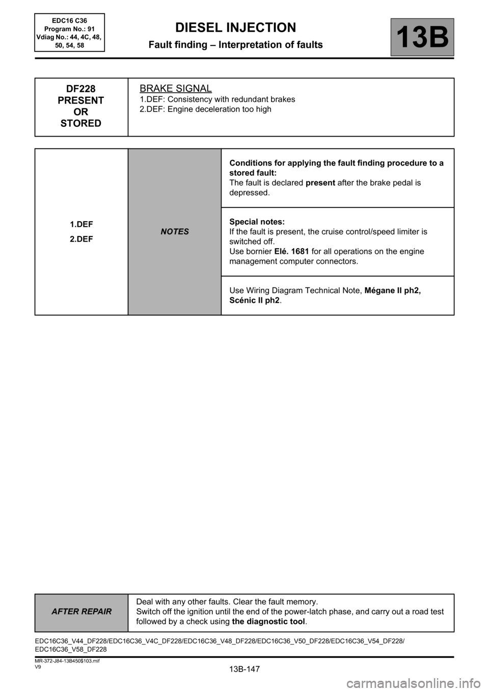
DF228
PRESENT
OR
STOREDBRAKE SIGNAL
1.DEF: Consistency with redundant brakes
2.DEF: Engine deceleration too high
1.DEF
2.DEF
NOTESConditions for applying the fault finding procedure to a
stored fault:
The fault is declared present after the brake pedal is
depressed.
Special notes:
If the fault is present, the cruise control/speed limiter is
switched off.
Use bornier Elé. 1681 for all operations on the engine
management computer connectors.
Use Wiring Diagram Technical Note, Mégane II ph2,
Scénic II ph2.
EDC16C36_V44_DF228/EDC16C36_V4C_DF228/EDC16C36_V48_DF228/EDC16C36_V50_DF228/EDC16C36_V54_DF228/
EDC16C36_V58_DF228EDC16 C36
Program No.: 91
Vdiag No.: 44, 4C, 48,
50, 54, 58
Page 148 of 431

13B-148
AFTER REPAIRDeal with any other faults. Clear the fault memory.
Switch off the ignition until the end of the power-latch phase, and carry out a road test
followed by a check using the diagnostic tool.
V9 MR-372-J84-13B450$103.mif
DIESEL INJECTION
Fault finding – Interpretation of faults13B
DF228
CONTINUED 1
From the List of Statuses menu, check ET012 and ET013 and check:
– brake pedal in rest position ET012 = "RELEASED" and ET013 = "RELEASED"
– brake pedal depressed ET012 = "DEPRESSED" and ET013 = "DEPRESSED"
Has ET013 been correctly recognised?
Has ET012 been correctly recognised?Clear the fault
End of fault finding
procedure
Check the connections of the brake pedal switch, the ABS computer, the electronic stability program
computer and the engine management computer.
If there is a repair method (see Technical Note 6015A, Repairing electrical wiring, Wiring:
Precautions for repair), repair the wiring, otherwise replace it.
Check for + 12 V after ignition feed on the connections of the brake pedal switch connector and the
condition of the fuse.
– Connection code AP10 of component 160.
– Connection code SP13 of component 160.
Disconnect the ABS - ESP and check the continuity and insulation against + 12 V and against earth
of the following connection:
– Connection code 65A between components 160 and 1094.
Check that the brake pedal switch is working correctly:
in rest position: infinite resistance continuity between the following connections:
– Connection code 65A of component 160.
– Connection code AP10 of component 160.
depressed: continuity between the following connections:
– Connection code 65A of component 160.
– Connection code AP10 of component 160.
Replace the switch if necessary.
If the fault is still present, carry out fault finding on the anti-lock braking system - electronic stability
program; if no irregularity is detected, then carry out fault finding on the multiplex network.
YES
YES
NONO
A
EDC16 C36
Program No.: 91
Vdiag No.: 44, 4C, 48,
50, 54, 58