RENAULT TWINGO 2009 2.G Electrical Equipment Workshop Manual
Manufacturer: RENAULT, Model Year: 2009, Model line: TWINGO, Model: RENAULT TWINGO 2009 2.GPages: 241
Page 111 of 241
86B-1
CAR PHONE
Car phone: List and location of components
HANDS-FREE TELEPHONE KIT
86B
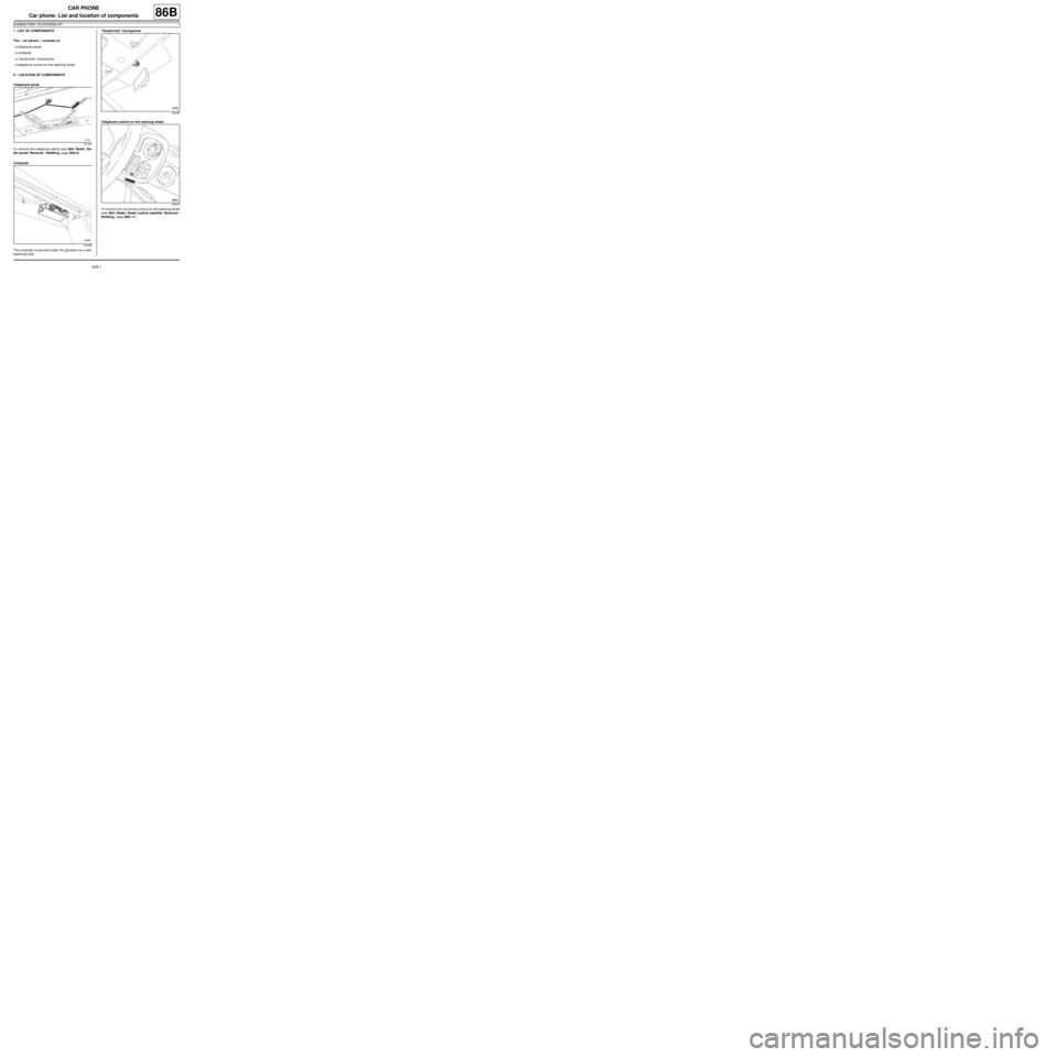
I - LIST OF COMPONENTS
The « car phone » consists of:
-a telephone aerial
-a computer
-a "hands-free" microphone
-a telephone control on the steering wheel
II - LOCATION OF COMPONENTS
Telephone aerial
To remove the telephone aerial (see 86A, Radio, Ra-
dio aerial: Removal - Refitting, page 86A-5) .
Computer
The computer is secured under the glovebox by a self-
fastening strip."Hands-free" microphone
Telephone control on the steering wheel
To remove the car phone control on the steering wheel
(see 86A, Radio, Radio control satellite: Removal -
Refitting, page 86A-11) .
121087
132408
132406
109918
Page 112 of 241
86B-2
CAR PHONE
"Hands-free" microphone: Removal - Refitting
HANDS-FREE TELEPHONE KIT
86B
REMOVAL
I - REMOVAL PREPARATION OPERATION
aDisconnect the battery (see 80A, Battery, Battery:
Removal - Refitting, page 80A-2) .
aRemove the computer (see 86B, Car phone, Com-
puter: Removal - Refitting, page 86B-4) .
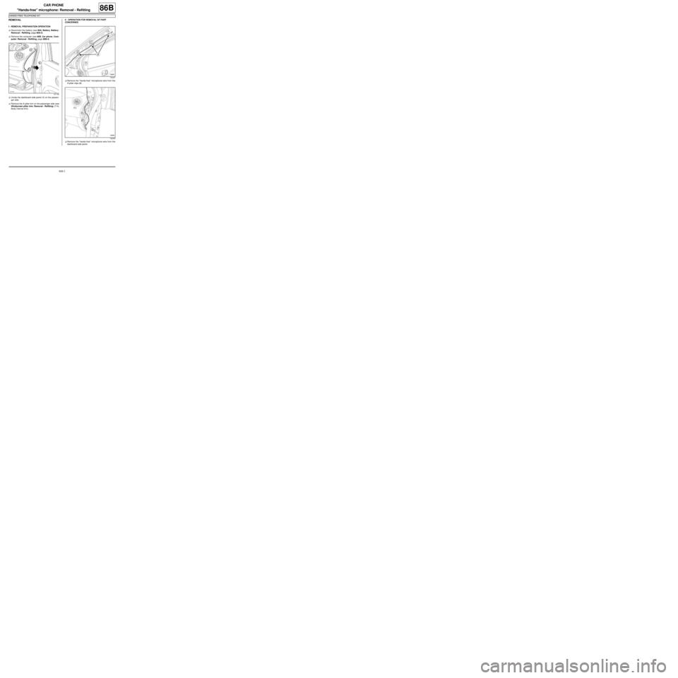
aUnclip the dashboard side panel (1) on the passen-
ger side.
aRemove the A-pillar trim on the passenger side (see
Windscreen pillar trim: Removal - Refitting) (71A,
Body internal trim).II - OPERATION FOR REMOVAL OF PART
CONCERNED
aRemove the “hands-free” microphone wire from the
A-pillar clips (2) .
aRemove the “hands-free” microphone wire from the
dashboard side panel.
121136
132407
132405
Page 113 of 241
86B-3
CAR PHONE
"Hands-free" microphone: Removal - Refitting
HANDS-FREE TELEPHONE KIT
86B
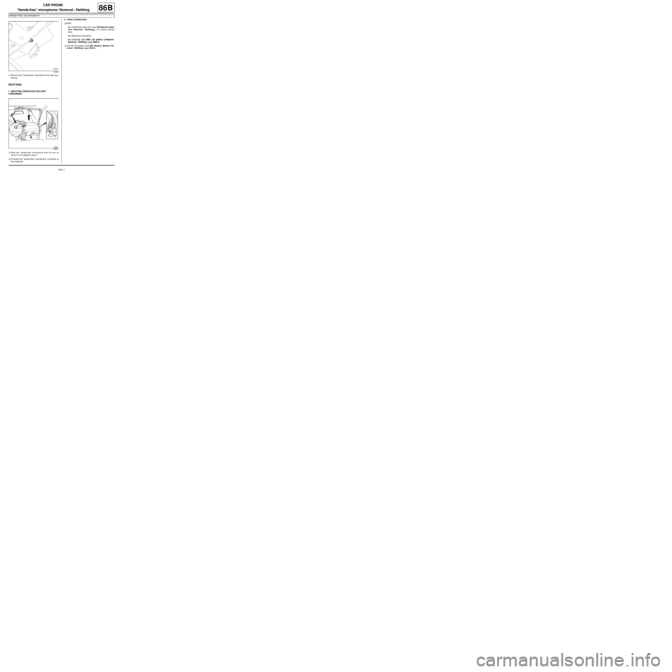
aRemove the “hands-free” microphone from the hea-
dlining.
REFITTING
I - REFITTING OPERATION FOR PART
CONCERNED
aRefit the “hands-free” microphone with its wire as
shown in the diagram above.
aConnect the “hands-free” microphone connector to
the computer.II - FINAL OPERATION.
aRefit:
-the windscreen pillar trim (see Windscreen pillar
trim: Removal - Refitting) (71A, Body internal
trim),
-the dashboard side panel,
-the computer (see 86B, Car phone, Computer:
Removal - Refitting, page 86B-4) .
aConnect the battery (see 80A, Battery, Battery: Re-
moval - Refitting, page 80A-2) .
132406
132410
Page 114 of 241

86B-4
CAR PHONE
Computer: Removal - Refitting
HANDS-FREE TELEPHONE KIT
86B
REMOVAL
I - REMOVAL PREPARATION OPERATION
aDisconnect the battery (see 80A, Battery, Battery:
Removal - Refitting, page 80A-2) .
II - OPERATION FOR REMOVAL OF PART
CONCERNED
aRemove the computer.
aDisconnect the computer connectors (1) .
REFITTING
I - REFITTING OPERATION FOR PART
CONCERNED
aConnect the computer connectors.
aRefit the computer in its original position.II - FINAL OPERATION.
aConnect the battery (see 80A, Battery, Battery: Re-
moval - Refitting, page 80A-2) .
aIf replacing the computer, carry out the necessary
operations using the Diagnostic tool (see Fault fin-
ding - Replacement of components) (86B, Car
phone). Equipment required
Diagnostic tool
Note:
The computer is secured under the glovebox by a
self-fastening strip.
132408
Page 115 of 241
87B-1
PASSENGER COMPARTMENT CONNECTION UNIT
UCH: Removal - Refitting
87B
REMOVAL
I - OPERATION FOR REMOVAL OF PART
CONCERNED
aWhen replacing, carry out the necessary operations
using the Diagnostic tool (see Fault finding - Re-
placement of components) (MR 413, 87B, Pas-
senger compartment connection unit).
a
aLock the airbag computer using the Diagnostic tool
(see Fault finding - Replacement of compo-
nents)(MR 413, 88C, Airbags and seat belt preten-
sioners).
aSwitch off the ignition.
aDisconnect the battery (see 80A, Battery, Battery:
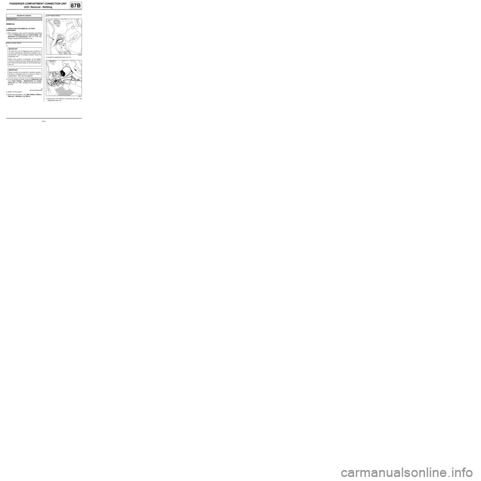
Removal - Refitting, page 80A-2) .aUnclip the dashboard lower trim (1)
aDisconnect the different connectors (2) from the
dashboard lower trim. Equipment required
Diagnostic tool
RIGHT-HAND DRIVE
IMPORTANT
To avoid any risk of triggering when working on
or near a pyrotechnic component (airbags or pre-
tensioners), lock the airbag computer using the
diagnostic tool.
When this function is activated, all the trigger
lines are inhibited and the airbag warning light on
the instrument panel lights up continuously (igni-
tion on).
IMPORTANT
Never handle the pyrotechnic systems (preten-
sioners or airbags) near to a source of heat or
naked flame - they may be triggered.
LEFT-HAND DRIVE
120278
119711
Page 116 of 241
87B-2
PASSENGER COMPARTMENT CONNECTION UNIT
UCH: Removal - Refitting
87B
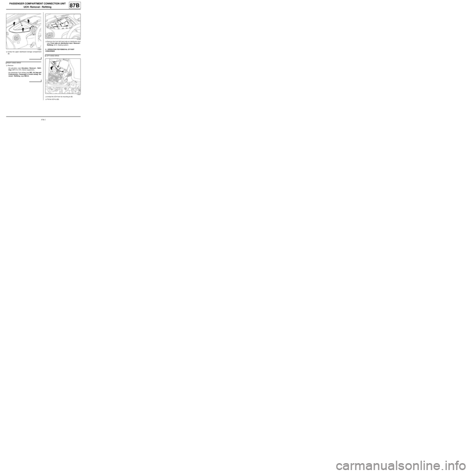
aUnclip the upper dashboard storage compartment
(3) .
aRemove:
-the glovebox (see Glovebox: Removal - Refit-
ting) (MR 412, 57A, Interior equipment),
-the passenger front airbag (see 88C, Air bag and
Pretensioners, Passenger's frontal airbag: Re-
moval - Refitting, page 88C-8) .aRemove the front left-hand side air distribution duct
(see Front side air distribution duct: Removal -
Refitting) (61A, Heating system).
II - OPERATION FOR REMOVAL OF PART
CONCERNED
aUnclip the UCH from its mounting at (5) .
aTilt the UCH at (6) .
119502
RIGHT-HAND DRIVE
121208
LEFT-HAND DRIVE
119507
Page 117 of 241
87B-3
PASSENGER COMPARTMENT CONNECTION UNIT
UCH: Removal - Refitting
87B
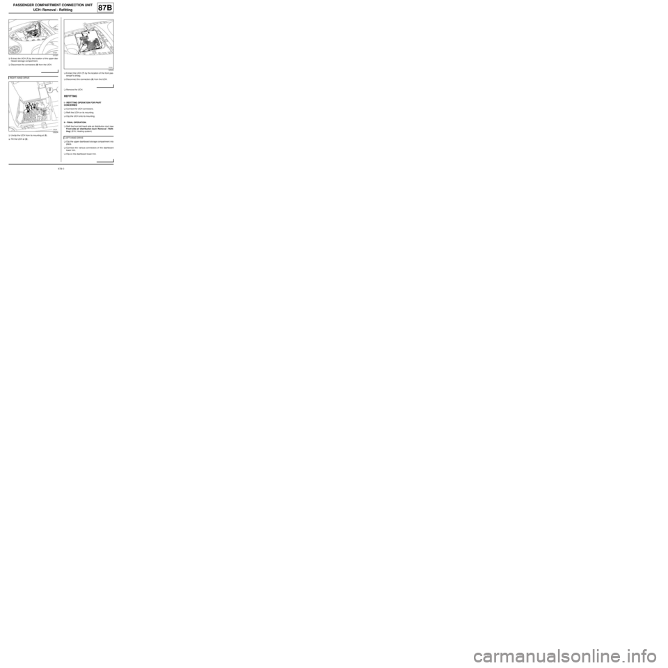
aExtract the UCH (7) by the location of the upper das-
hboard storage compartment.
aDisconnect the connectors (8) from the UCH.
aUnclip the UCH from its mounting at (5) .
aTilt the UCH at (6) .aExtract the UCH (7) by the location of the front pas-
senger's airbag.
aDisconnect the connectors (8) from the UCH.
aRemove the UCH.
REFITTING
I - REFITTING OPERATION FOR PART
CONCERNED
aConnect the UCH connectors.
aRefit the UCH on its mounting.
aClip the UCH onto its mounting.
II - FINAL OPERATION.
aRefit the front left-hand side air distribution duct (see
Front side air distribution duct: Removal - Refit-
ting) (61A, Heating system).
aClip the upper dashboard storage compartment into
place.
aConnect the various connectors of the dashboard
lower trim.
aClip on the dashboard lower trim.
121207
RIGHT-HAND DRIVE
125234
125235
LEFT-HAND DRIVE
Page 118 of 241

87B-4
PASSENGER COMPARTMENT CONNECTION UNIT
UCH: Removal - Refitting
87B
aRefit:
-the passenger front airbag (see 88C, Air bag and
Pretensioners, Passenger's frontal airbag: Re-
moval - Refitting, page 88C-8) ,
-the glovebox (see Glovebox: Removal - Refit-
ting) (MR 412, 57A, Interior equipment).
aConnect the battery (see 80A, Battery, Battery: Re-
moval - Refitting, page 80A-2) .
aUnlock the airbag computer using the Diagnostic
tool (see Fault finding - Replacement of compo-
nents)(MR 413, 88C, Airbags and seat belt preten-
sioners).
aWhen replacing, carry out the necessary operations
using the Diagnostic tool (see Fault finding - Re-
placement of components) (MR 413, 87B, Pas-
senger compartment connection unit). RIGHT-HAND DRIVE
RIGHT-HAND DRIVE
Page 119 of 241
87C-1
OPENING ELEMENT MANAGEMENT
Opening elements management: List and location of components87C
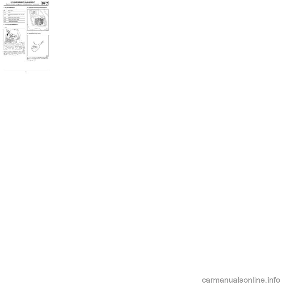
I - LIST OF COMPONENTS
II - LOCATION OF COMPONENTS
1 - UCH
The UCH is located in the dashboard, above the pas-
senger compartment relay/fuse box; to remove it (see
87B, Passenger compartment connection unit,
UCH: Removal - Refitting, page 87B-1) .2 - Passenger compartment fuse and relay box
3 - Remote door locking control
To replace the battery (see 82A, Engine immobiliser,
Battery for remote door locking control: Removal -
Refitting, page 82A-8) . No. Description
(1) UCH
(2) Passenger compartment fuse and relay
box
(3) Remote door locking control
(4) Centr al door locking switch
(5) Tailgate opening switch
119507
119504
107733
Page 120 of 241

87C-2
OPENING ELEMENT MANAGEMENT
Opening elements management: List and location of components87C
4 - Central door locking switch
To remove it (see 84A, Control - Signals, Hazard
warning lights and central door control: Removal -
Refitting, page 84A-10) .
5 - Tailgate opening switch
121084
120162