K4M RENAULT TWINGO RS 2009 2.G Engine And Peripherals Workshop Manual
[x] Cancel search | Manufacturer: RENAULT, Model Year: 2009, Model line: TWINGO RS, Model: RENAULT TWINGO RS 2009 2.GPages: 652
Page 486 of 652

17B-11
PETROL INJECTION
Petrol injection: List and location of components
K4M
17B
119373
(7) Switching protection unit
131762
(8) Coolant temper ature sensor
132391
(9) Camshaft position sensor
132374
(10) Pinking sensor
(11) Oil pressure sensor
Page 487 of 652

17B-12
PETROL INJECTION
Petrol injection: List and location of components
K4M
17B
132390
(13) Injector rail
132539
(14) upstream oxygen sensor
132378
(15) Downstream oxygen sensor
132445
(16) Crankshaft position sensor
Page 492 of 652
17B-17
PETROL INJECTION
Oxygen sensors: Removal - Refitting
K4M
17B
REMOVING THE UPSTREAM OXYGEN
SENSOR
I - REMOVAL PREPARATION OPERATION
aPosition the vehicle on a two-post lift (see Vehicle:
Towing and lifting) (02A, Lifting equipment).
aRemove:
-the front right-hand wheel (see Wheel: Removal -
Refitting) (35A, Wheels and tyres),-the front right-hand wheel arch liner (see Front
wheel arch liner: Removal - Refitting) (55A, Ex-
terior protection),
-the engine undertray.
II - REMOVAL OPERATION
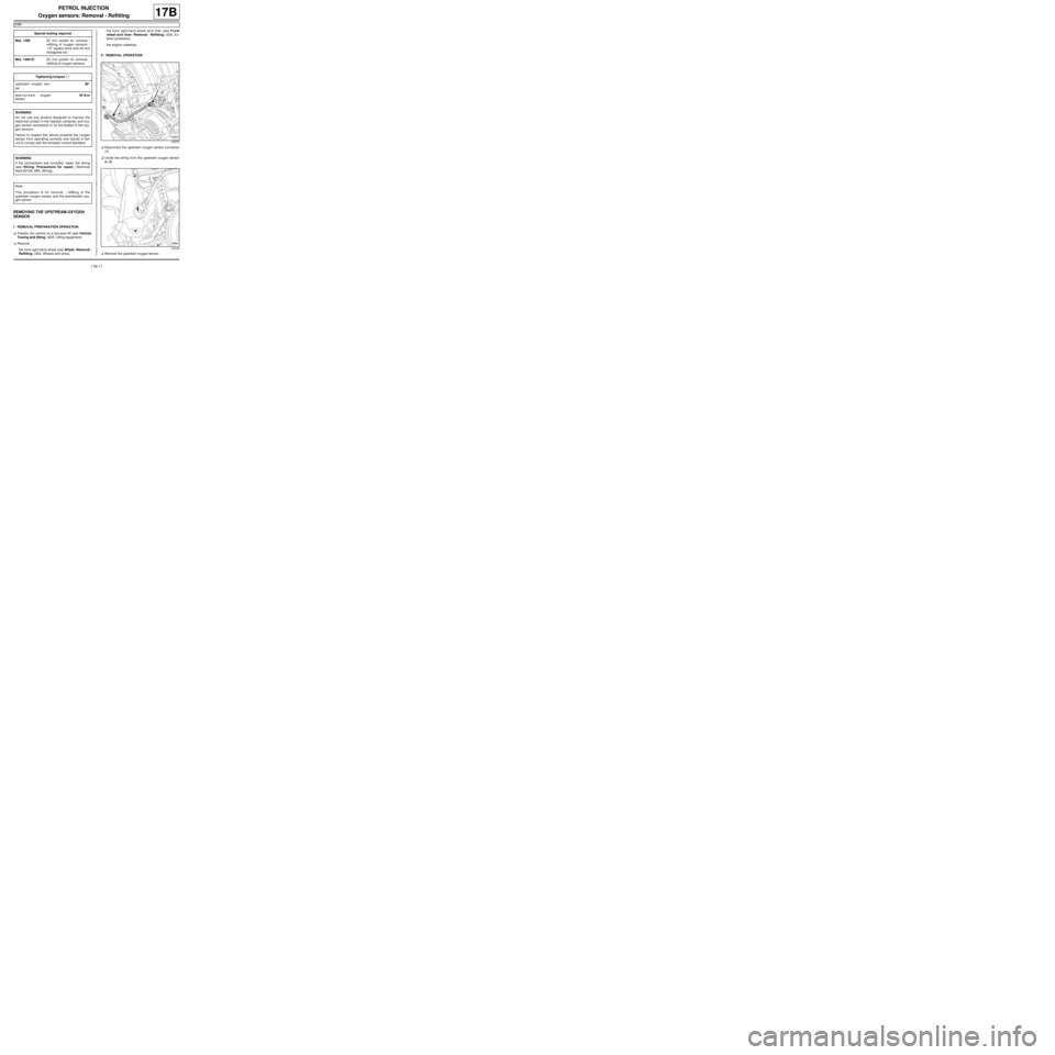
aDisconnect the upstream oxygen sensor connector
(1) .
aUnclip the wiring from the upstream oxygen sensor
at (2) .
aRemove the upstream oxygen sensor . Special tooling required
Mot. 149522 mm socket for removal -
refitting of oxygen sensors -
1/2" square dr ive and 24 mm
hexagonal ext.
Mot. 1495-0122 mm socket for removal -
refitting of oxygen sensors.
Tightening torquesm
upstream oxygen sen-
sor90˚
downstream oxygen
sensor45 N.m
WARNING
Do not use any product designed to improve the
electr ical contact in the injection computer and oxy-
gen sensor connectors or on the bodies of the oxy-
gen sensors.
Failure to respect this advice prevents the oxygen
sensor from operating correctly and results in fail-
ure to comply with the emission control standard.
WARNING
If the connections are corroded, repair the wiring
(see Wiring: Precautions for repair) (Technical
Note 6015A, 88A, Wiring).
Note:
This procedure is for removal - refitting of the
upstream oxygen sensor and the downstream oxy-
gen sensor.
132373
132539
Page 493 of 652
17B-18
PETROL INJECTION
Oxygen sensors: Removal - Refitting
K4M
17B
REFITTING THE UPSTREAM OXYGEN
SENSOR
I - REFITTING PREPARATION OPERATION
aClean the threading of the upstream oxygen sensor
using a WIRE BRUSH.
aUse SURFACE CLEANER (see Vehicle: Parts
and consumables for the repair) (04B, Consuma-
bles - Products) to clean and degrease:
-the thread hole of the upstream oxygen sensor on
the exhaust manifold,
-the threading of the upstream oxygen sensor if it is
to be reused.
II - REFITTING OPERATION
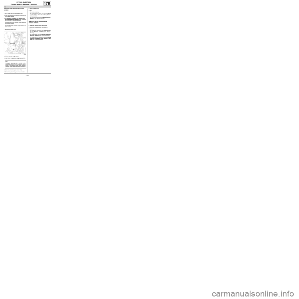
aRefit the upstream oxygen sensor.
aAngle tighten the upstream oxygen sensor ( 90˚).
aAttach the upstream oxygen sensor wiring.
aConnect the upstream oxygen sensor connector.III - FINAL OPERATION
aRefit:
-the engine undertray.
-the front right-hand wheel arch liner (see Front
wheel arch liner: Removal - Refitting) (55A, Ex-
terior protection),
-the front right-hand wheel (see Wheel: Removal -
Refitting) (35A, Wheels and tyres).
REMOVAL OF THE DOWNSTREAM
OXYGEN SENSOR
I - REMOVAL PREPARATION OPERATION
aDisconnect the battery (see ) (80A, Battery).
aRemove:
-the windscreen wiper arms (see Windscreen wip-
er arm: Removal - Refitting) (85A, Wiping -
Washing),
-the scuttle panel grille (see Scuttle panel grille:
Removal - Refitting) (56A, Exterior equipment),
-the scoop under the scuttle panel grille (see Scoop
under the scuttle panel grille: Removal - Refit-
ting) (56A, Exterior equipment).
132539
Note:
For angular tightening, make a mark (6) on the
catalytic pre-converter in the middle of the flat
surface of the upstream oxygen sensor. Move the
upstream oxygen sensor stop (7) to the mark (6)
.
Page 494 of 652
17B-19
PETROL INJECTION
Oxygen sensors: Removal - Refitting
K4M
17B
II - REMOVAL OPERATION
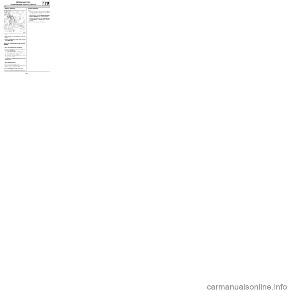
aDisconnect the downstream oxygen sensor connec-
tor (3) .
aUnclip the wiring from the downstream oxygen sen-
sor at (4) .
aRemove the downstream oxygen sensor (5) using
the tool (Mot. 1495).
REFITTING THE DOWNSTREAM OXYGEN
SENSOR
I - REFITTING PREPARATION OPERATION
aClean the threading of the downstream oxygen sen-
sor using a WIRE BRUSH.
aUse SURFACE CLEANER (see Vehicle: Parts
and consumables for the repair) (04B, Consuma-
bles - Products) to clean and degrease:
-the thread hole of the downstream oxygen sensor
on the exhaust manifold,
-the threading of the downstream oxygen sensor if it
is to be reused.
II - REFITTING OPERATION
aRefit the downstream oxygen sensor.
aTorque tighten the downstream oxygen sensor
(45 N.m) using the tool (Mot. 1495-01).
aClip on the downstream oxygen sensor wiring.
aConnect the downstream oxygen sensor connector.III - FINAL OPERATION
aRefit:
-the scoop under the scuttle panel grille (see Scoop
under the scuttle panel grille: Removal - Refit-
ting) (56A, Exterior equipment),
-the scuttle panel grille (see Scuttle panel grille:
Removal - Refitting) (56A, Exterior equipment),
-the windscreen wiper arms (see Windscreen wip-
er arm: Removal - Refitting) (85A, Wiping -
Washing).
aConnect the battery (see ) (80A, Battery).
132378
Page 496 of 652
17B-21
PETROL INJECTION
Petrol injection computer: Removal - Refitting
K4M
17B
REMOVAL
I - REMOVAL PREPARATION OPERATION
aRemove the battery (see Battery: Removal - Refit-
ting) (80A, Battery).aRemove:
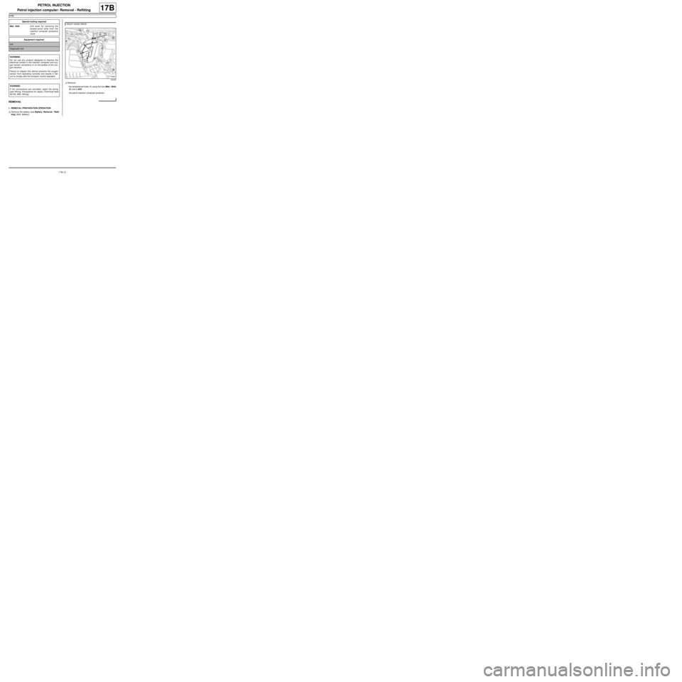
-the tamperproof bolts (1) using the tool (Mot. 1844)
(2) and a drill,
-the petrol injection computer protector. Special tooling required
Mot. 1844Drill bush for removing the
tamper-proof bolts from the
injection computer protective
cover
Equipment required
drill
Diagnostic tool
WARNING
Do not use any product designed to improve the
electr ical contact in the injection computer and oxy-
gen sensor connectors or on the bodies of the oxy-
gen sensors.
Failure to respect this advice prevents the oxygen
sensor from operating correctly and results in fail-
ure to comply with the emission control standard.
WARNING
If the connections are corroded, repair the wiring
(see Wiring: Precautions for repair) (Technical Note
6015A, 88A, Wiring).
RIGHT-HAND DRIVE
132448
Page 497 of 652
17B-22
PETROL INJECTION
Petrol injection computer: Removal - Refitting
K4M
17B
II - REMOVAL OPERATION
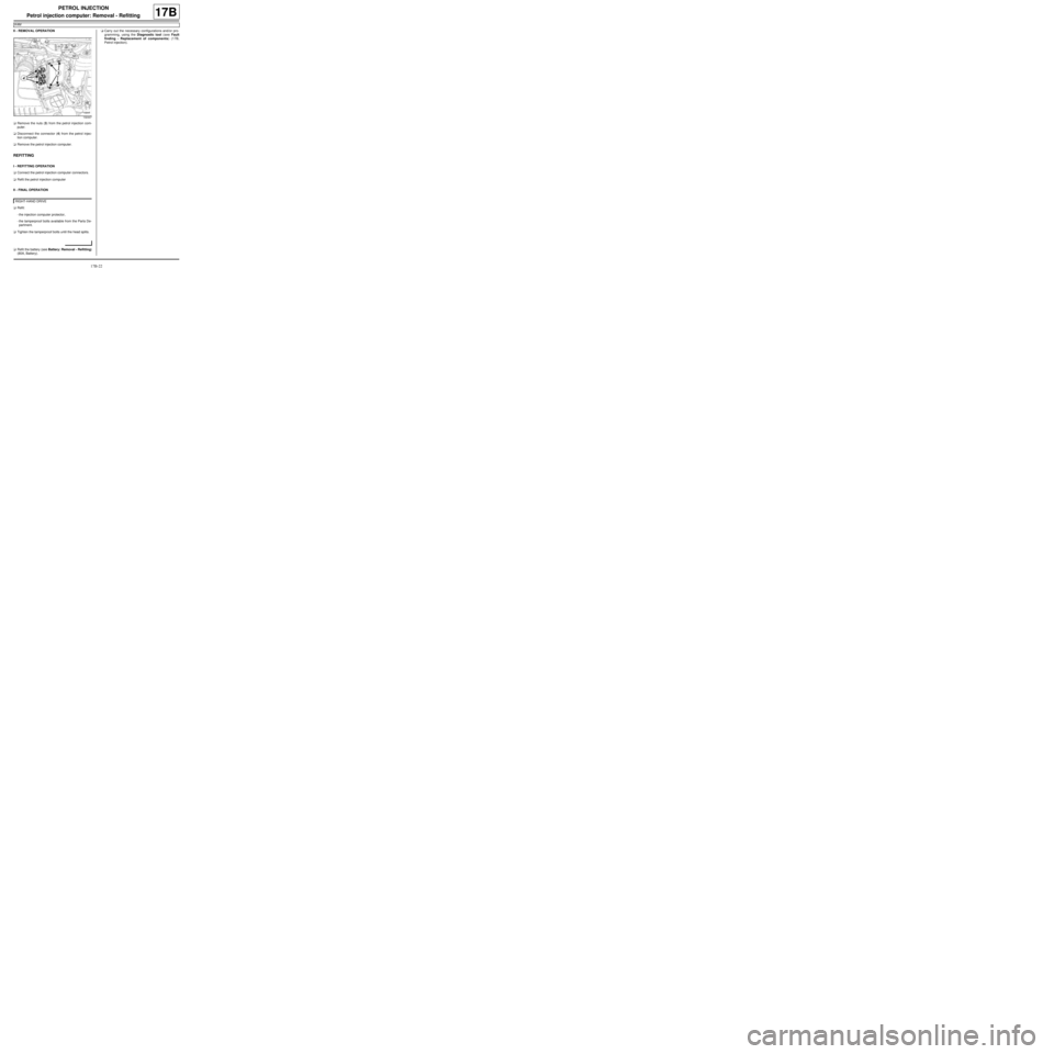
aRemove the nuts (3) from the petrol injection com-
puter.
aDisconnect the connector (4) from the petrol injec-
tion computer.
aRemove the petrol injection computer.
REFITTING
I - REFITTING OPERATION
aConnect the petrol injection computer connectors.
aRefit the petrol injection computer
II - FINAL OPERATION
aRefit:
-the injection computer protector,
-the tamperproof bolts available from the Parts De-
partment.
aTighten the tamperproof bolts until the head splits.
aRefit the battery (see Battery: Removal - Refitting)
(80A, Battery).aCarry out the necessary configurations and/or pro-
gramming, using the Diagnostic tool (see Fault
finding - Replacement of components) (17B,
Petrol injection).
132447
RIGHT-HAND DRIVE
Page 498 of 652
17B-23
PETROL INJECTION
Pinking sensor: Removal - Refitting
K4M
17B
REMOVAL
I - REMOVAL PREPARATION OPERATION
aRemove:
-the dipstick,
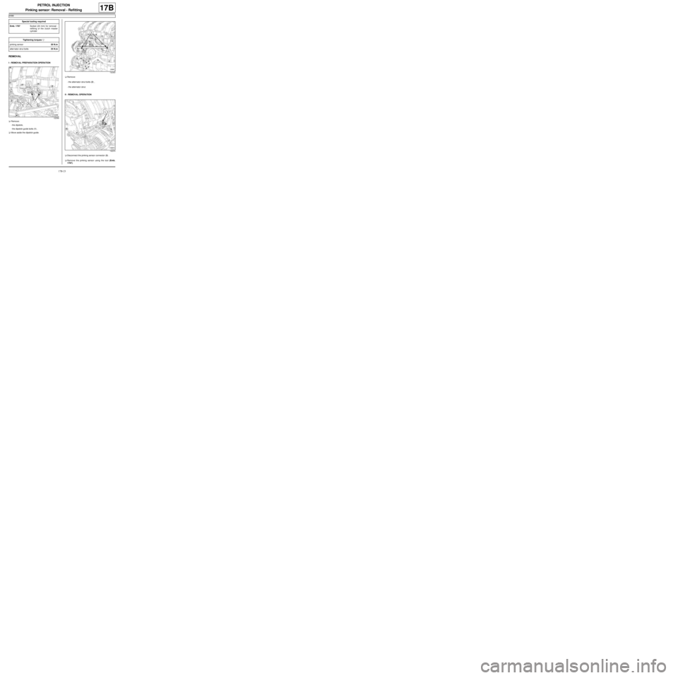
-the dipstick guide bolts (1) .
aMove aside the dipstick guide.aRemove:
-the alternator strut bolts (2) ,
-the alternator strut.
II - REMOVAL OPERATION
aDisconnect the pinking sensor connector (3) .
aRemove the pinking sensor using the tool (Emb.
1797). Special tooling required
Emb. 1797Socket (24 mm) for removal -
refitting of the clutch master
cylinder
Tightening torquesm
pinking sensor20 N.m
alter nator strut bolts25 N.m
132368
132363
132374
Page 499 of 652
17B-24
PETROL INJECTION
Pinking sensor: Removal - Refitting
K4M
17B
REFITTING
I - REFITTING OPERATION
aRefit the pinking sensor.
aTorque tighten the pinking sensor (20 N.m) using
the tool (Emb. 1797).
aConnect the pinking sensor connector.
II - FINAL OPERATION
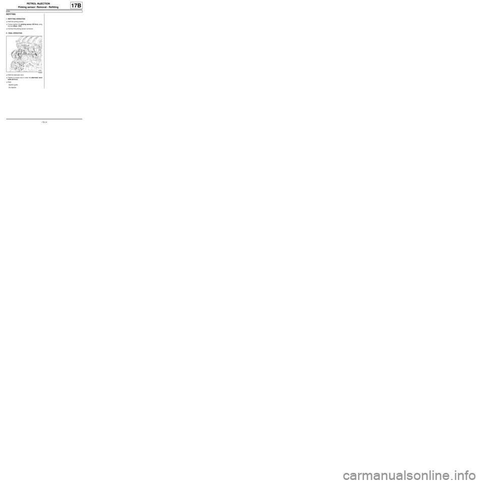
aRefit the alternator strut.
aTighten to torque and in order the alternator strut
bolts (25 N.m).
aRefit:
-dipstick guide ,
-the dipstick.
132363
Page 501 of 652
17B-26
PETROL INJECTION
Crankshaft position sensor: Removal - Refitting
K4M
17B
REMOVAL
I - REMOVAL PREPARATION OPERATION
aPosition the vehicle on a two-post lift (see Vehicle:
Towing and lifting) (02A, Lifting equipment).
aRemove the engine undertray.
II - REMOVAL OPERATION
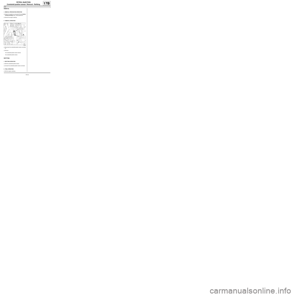
aDisconnect the crankshaft position sensor connector
(1) .
aRemove:
-the crankshaft position sensor bolt (2) ,
-the crankshaft position sensor.
REFITTING
I - REFITTING OPERATION
aRefit the crankshaft position sensor.
aConnect the crankshaft position sensor connector.
II - FINAL OPERATION
aRefit the engine undertray.
132445