K4M RENAULT TWINGO RS 2009 2.G Engine And Peripherals Workshop Manual
[x] Cancel search | Manufacturer: RENAULT, Model Year: 2009, Model line: TWINGO RS, Model: RENAULT TWINGO RS 2009 2.GPages: 652
Page 531 of 652
19A-21
COOLING
Cooling radiator: Removal - Refitting
K4M
19A
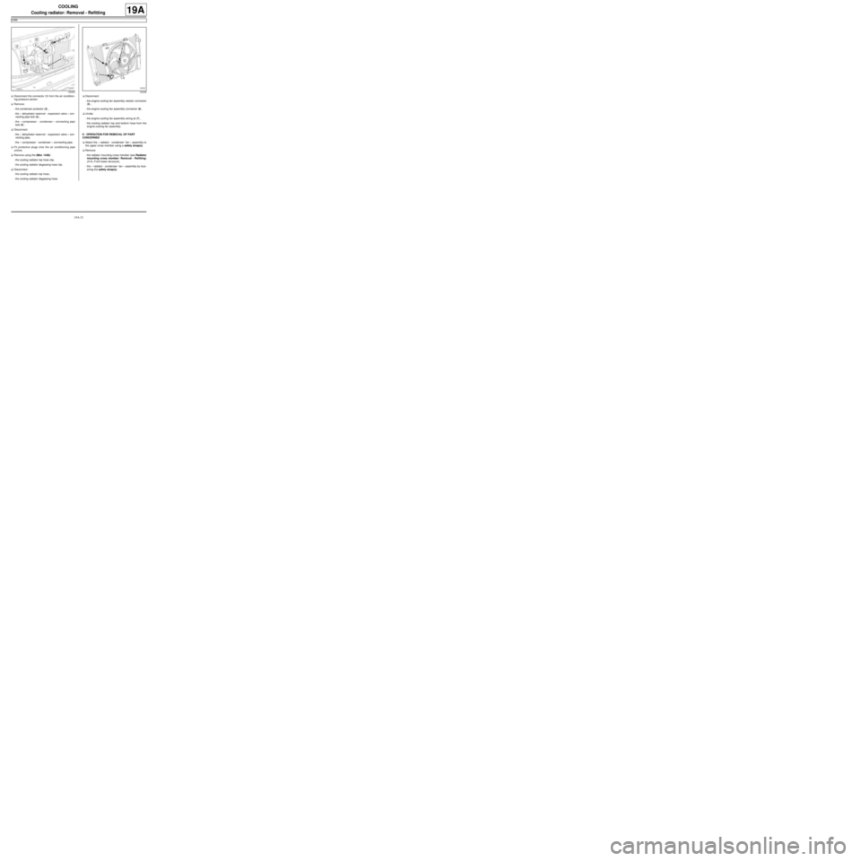
aDisconnect the connector (1) from the air condition-
ing pressure sensor.
aRemove:
-the condenser protector (2) ,
-the « dehydrator reservoir - expansion valve » con-
necting pipe bolt (3) ,
-the « compressor - condenser » connecting pipe
bolt (4) .
aDisconnect:
-the « dehydrator reservoir - expansion valve » con-
necting pipe,
-the « compressor - condenser » connecting pipe.
aFit protective plugs onto the air conditioning pipe
unions.
aRemove using the (Mot. 1448) :
-the cooling radiator top hose clip,
-the cooling radiator degassing hose clip.
aDisconnect:
-the cooling radiator top hose,
-the cooling radiator degassing hose.aDisconnect:
-the engine cooling fan assembly resistor connector
(5) ,
-the engine cooling fan assembly connector (6) .
aUnclip:
-the engine cooling fan assembly wiring at (7) ,
-the cooling radiator top and bottom hose from the
engine cooling fan assembly.
II - OPERATION FOR REMOVAL OF PART
CONCERNED
aAttach the « radiator - condenser- fan » assembly to
the upper cross member using a safety strap(s).
aRemove:
-the radiator mounting cross member (see Radiator
mounting cross member: Removal - Refitting)
(41A, Front lower structure),
-the « radiator - condenser- fan » assembly by loos-
ening the safety strap(s).
132335132336
Page 532 of 652
19A-22
COOLING
Cooling radiator: Removal - Refitting
K4M
19A
On the workbench
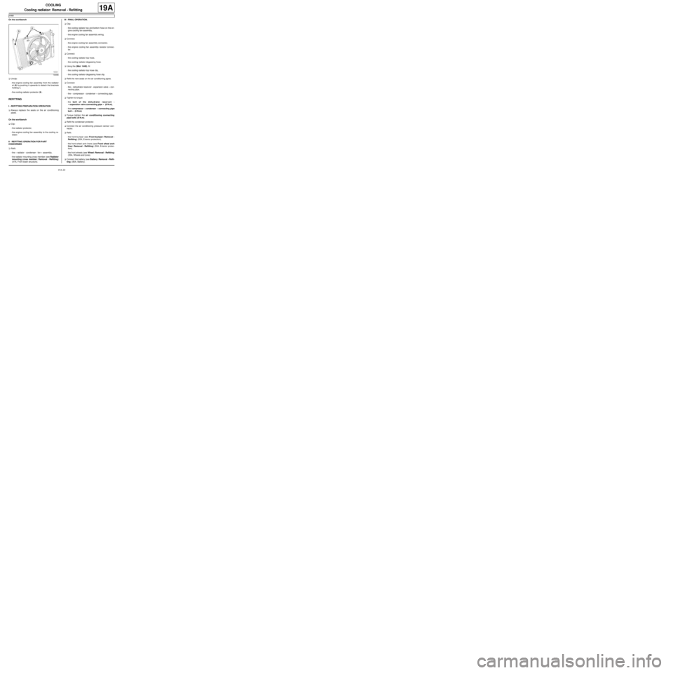
aUnclip:
-the engine cooling fan assembly from the radiator
at (8) by pushing it upwards to detach the brackets
holding it,
-the cooling radiator protector (9) .
REFITTING
I - REFITTING PREPARATION OPERATION
aAlways replace the seals on the air conditioning
pipes.
On the workbench
aClip:
-the radiator protector,
-the engine cooling fan assembly to the cooling ra-
diator.
II - REFITTING OPERATION FOR PART
CONCERNED
aRefit:
-the « radiator - condenser - fan » assembly,
-the radiator mounting cross member (see Radiator
mounting cross member: Removal - Refitting)
(41A, Front lower structure).III - FINAL OPERATION.
aClip:
-the cooling radiator top and bottom hose on the en-
gine cooling fan assembly,
-the engine cooling fan assembly wiring.
aConnect:
-the engine cooling fan assembly connector,
-the engine cooling fan assembly resistor connec-
tor.
aConnect:
-the cooling radiator top hose,
-the cooling radiator degassing hose.
aUsing the (Mot. 1448), fit:
-the cooling radiator top hose clip,
-the cooling radiator degassing hose clip.
aRefit the new seals on the air conditioning pipes.
aConnect:
-the « dehydrator reservoir - expansion valve » con-
necting pipe,
-the « compressor - condenser » connecting pipe.
aTighten to torque:
-the bolt of the dehydrator reservoir -
« expansion valve connecting pipe » (8 N.m),
-the compressor - condenser « connecting pipe
bolt » (8 N.m).
aTorque tighten the air conditioning connecting
pipe bolts (8 N.m).
aRefit the condenser protector.
aConnect the air conditioning pressure sensor con-
nector.
aRefit:
-the front bumper (see Front bumper: Removal -
Refitting) (55A, Exterior protection),
-the front wheel arch liners (see Front wheel arch
liner: Removal - Refitting) (55A, Exterior protec-
tion),
-the front wheels (see Wheel: Removal - Refitting)
(35A, Wheels and tyres).
aConnect the battery (see Battery: Removal - Refit-
ting) (80A, Battery).
132336
Page 533 of 652
19A-23
COOLING
Cooling radiator: Removal - Refitting
K4M
19A
aPerform the following operations:
-fill the air conditioning circuit using a refrigerant
charging station (see Refrigerant circuit: Drain-
ing - Filling) (62A, Air conditioning),
-fill and bleed the coolant circuit (see 19A, Cooling,
Cooling system: Draining - Refilling, page 19A-
9) .
aRefit the engine undertray.
Page 540 of 652
19A-30
COOLING
Coolant pump: Removal - Refitting
K4M
19A
REMOVAL
I - REMOVAL PREPARATION OPERATION
aPosition the vehicle on a two-post lift (see Vehicle:
Towing and lifting) (02A, Lifting equipment).
aDrain the cooling system (see 19A, Cooling, Cool-
ing system: Draining - Refilling, page 19A-9) .
aDisconnect the battery (see Battery: Removal - Re-
fitting) (80A, Battery).aRemove:
-the engine undertray,
-the front right-hand wheel (see Wheel: Removal -
Refitting) (35A, Wheels and tyres),
-the front right-hand wheel arch liner (see Front
wheel arch liner: Removal - Refitting) (55A, Ex-
terior protection),
-the front bumper (see Front bumper: Removal -
Refitting) (55A, Exterior protection),
-the headlights (see Halogen headlight: Removal
- Refitting) (80B, Headlights),
-the bonnet catch (see Bonnet lock: Removal -
Refitting) (52A, Non-side opening element mecha-
nisms),
-the front upper cross member (see Front upper
cross member: Removal - Refitting) (42A, Upper
front structure),
-the accessories belt (see 11A, Top and front of
engine, Accessories belt: Removal - Refitting,
page 11A-3) ,
-the air filter unit (see 12A, Fuel mixture, Air filter
unit: Removal - Refitting, page 12A-13) ,
-the throttle valve (see 12A, Fuel mixture, Throttle
valve: Removal - Refitting, page 12A-20) ,
-the windscreen wiper arms (see Windscreen wip-
er arm: Removal - Refitting) (85A, Wiping -
Washing),
-the scuttle panel grille (see Scuttle panel grille:
Removal - Refitting) (56A, Exterior equipment),
-the scoop under the scuttle panel grille (see Scoop
under the scuttle panel grille: Removal - Refit-
ting) (56A, Exterior equipment),
-the right-hand suspended engine mounting (see
19D, Engine mounting, Right-hand suspended
engine mounting: Removal - Refitting, page
19D-13) ,
-the crankshaft accessories pulley (see 11A, Top
and front of engine, Crankshaft accessories
pulley: Removal - Refitting, page 11A-20) ,
-the timing belt (see 11A, Top and front of engine,
Timing belt: Removal - Refitting, page 11A-27) ,
-the camshaft dephaser (see 11A, Top and front of
engine, Camshaft dephaser: Removal - Refit-
ting, page 11A-135) . Tightening torquesm
bolt 1 of the coolant
pump27 N.m
bolts 2 to 8 of the water
pump10 N.m
IMPORTANT
When working in the engine compartment, take
care as the radiator fan(s) may start up unexpect-
edly (risk of being cut).
To avoid any risk of serious burns when the engine
is hot:
-do not open the expansion bottle cap,
-do not drain the cooling system,
-do not open the bleed screw(s).
WARNING
Prepare for the flow of fluid, and protect the sur-
rounding components.
WARNING
When carr ying out a repair that requires a complete
change, it is essential to flush the circuit with clean
water, blast compressed air through the circuit to
drive out the water, fill and bleed the circuit and
then measure the effective protection.
The cr iteria to be met are:
-protection down to -25˚C ±± ± ±
2 for cold and temper-
ate countries,
-protection down to -40˚C ±± ± ±
2 for "extreme cold"
countries.
Page 541 of 652
19A-31
COOLING
Coolant pump: Removal - Refitting
K4M
19A
II - REMOVAL OPERATION
aRemove:
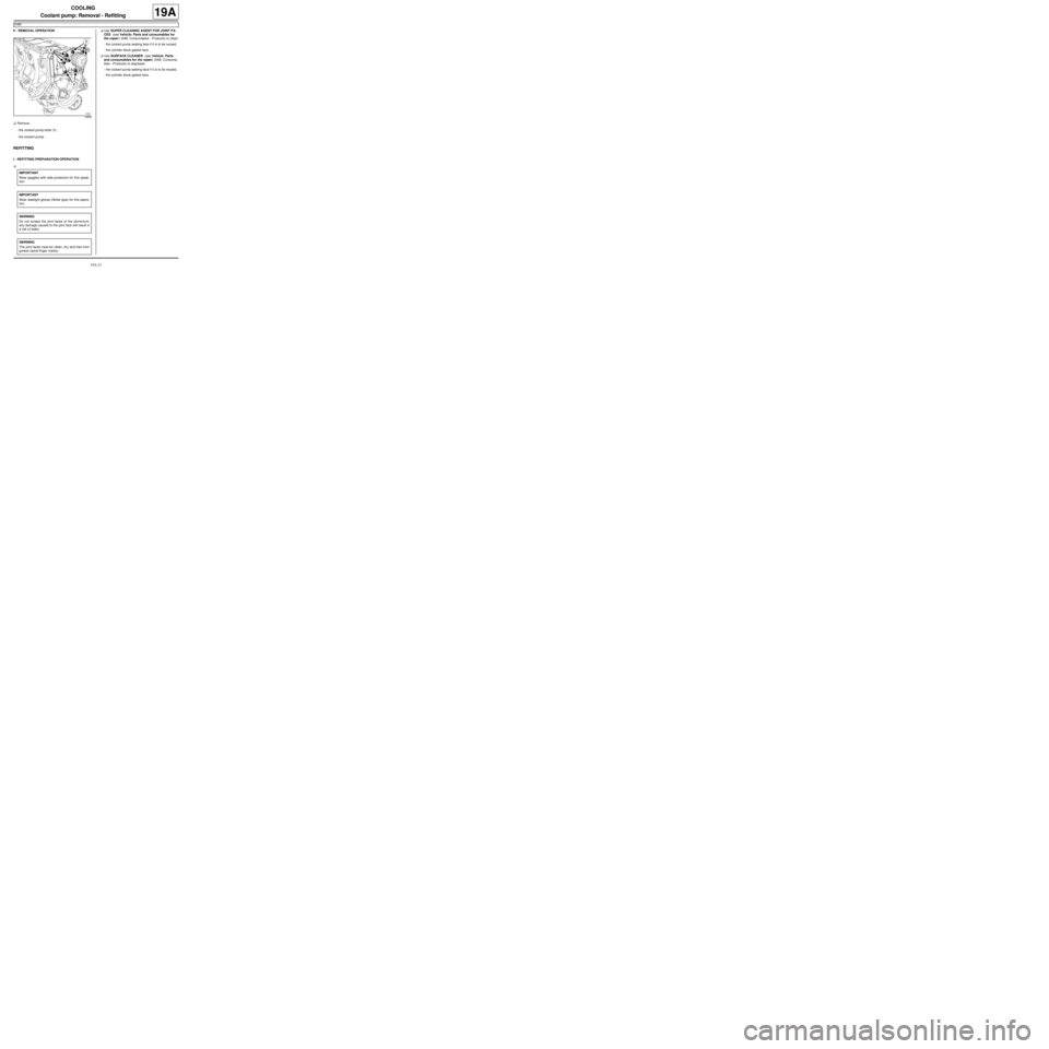
-the coolant pump bolts (1) ,
-the coolant pump.
REFITTING
I - REFITTING PREPARATION OPERATION
aaUse SUPER CLEANING AGENT FOR JOINT FA-
CES (see Vehicle: Parts and consumables for
the repair) (04B, Consumables - Products) to clean:
-the coolant pump sealing face if it is to be reused,
-the cylinder block gasket face.
aUse SURFACE CLEANER (see Vehicle: Parts
and consumables for the repair) (04B, Consuma-
bles - Products) to degrease:
-the coolant pump sealing face if it is to be reused,
-the cylinder block gasket face.
14505
IMPORTANT
Wear goggles with side protectors for this opera-
tion.
IMPORTANT
Wear leaktight gloves (Nitrile type) for this opera-
tion.
WARNING
Do not scrape the joint faces of the aluminium,
any damage caused to the joint face will result in
a risk of leaks.
WARNING
The joint faces must be clean, dr y and free from
grease (avoid finger marks).
Page 542 of 652
19A-32
COOLING
Coolant pump: Removal - Refitting
K4M
19A
a
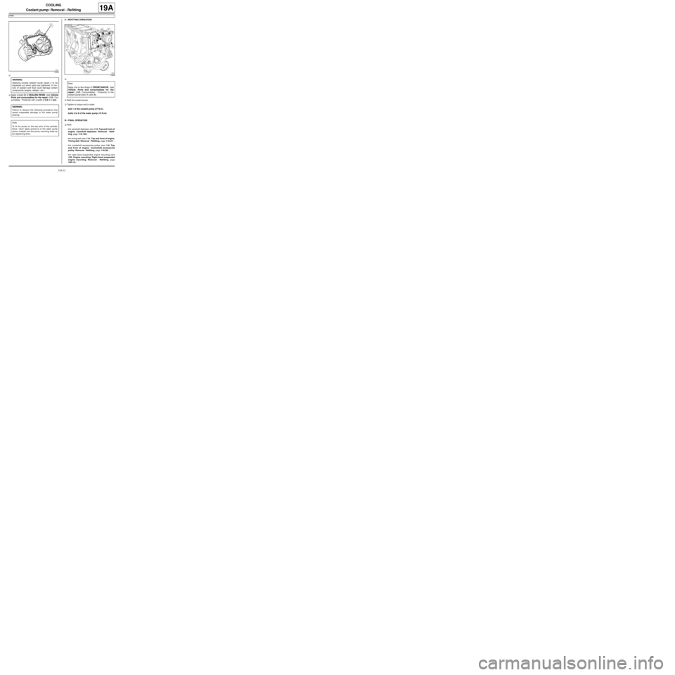
aApply a bead (2) of SEALING RESIN (see Vehicle:
Parts and consumables for the repair) (04B, Con-
sumables - Products) with a width of 0.6 to 1 mm.II - REFITTING OPERATION
a
aRefit the coolant pump.
aTighten to torque and in order:
-bolt 1 of the coolant pump (27 N.m),
-bolts 2 to 8 of the water pump (10 N.m).
III - FINAL OPERATION
aRefit:
-the camshaft dephaser (see 11A, Top and front of
engine, Camshaft dephaser: Removal - Refit-
ting, page 11A-135) ,
-the timing belt (see 11A, Top and front of engine,
Timing belt: Removal - Refitting, page 11A-27) ,
-the crankshaft accessories pulley (see 11A, Top
and front of engine, Crankshaft accessories
pulley: Removal - Refitting, page 11A-20) ,
-the right-hand suspended engine mounting (see
19D, Engine mounting, Right-hand suspended
engine mounting: Removal - Refitting, page
19D-13) ,
10063
WARNING
Applying excess sealant could cause it to be
squeezed out when parts are tightened. A mix-
ture of sealant and fluid could damage certain
components (engine, radiator, etc.).
WARNING
Failure to observe the following procedure may
cause irreparable damage to the water pump
bearing.
Note:
To fit the pump on the two pins of the cylinder
block, never apply pressure to the water pump
pinion; instead use the pump mounting bolts by
pre-tightening them.
14505
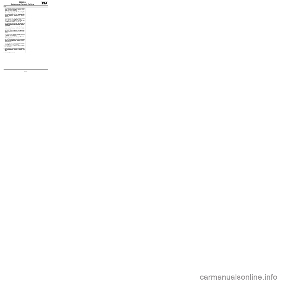
Note:
Apply one to tw o drops of FRENETANCHE (see
Vehicle: Parts and consumables for the
repair) (04B, Consumables - Products) to the
coolant pump bolts (1) and (4) .
Page 543 of 652
19A-33
COOLING
Coolant pump: Removal - Refitting
K4M
19A
-the scoop under the scuttle panel grille (see Scoop
under the scuttle panel grille: Removal - Refit-
ting) (56A, Exterior equipment),
-the scuttle panel grille (see Scuttle panel grille:
Removal - Refitting) (56A, Exterior equipment),
-the windscreen wiper arms (see Windscreen wip-
er arm: Removal - Refitting) (85A, Wiping -
Washing),
-the throttle valve (see 12A, Fuel mixture, Throttle
valve: Removal - Refitting, page 12A-20) ,
-the air filter unit (see 12A, Fuel mixture, Air filter
unit: Removal - Refitting, page 12A-13) ,
-the accessories belt (see 11A, Top and front of
engine, Accessories belt: Removal - Refitting,
page 11A-3) ,
-the front upper cross member (see Front upper
cross member: Removal - Refitting) (42A, Upper
front structure),
-the bonnet catch (see Bonnet lock: Removal -
Refitting) (52A, Non-side opening element mecha-
nisms),
-the headlights (see Halogen headlight: Removal
- Refitting) (80B, Headlights),
-the front bumper (see Front bumper: Removal -
Refitting) (55A, Exterior protection),
-the front right-hand wheel arch liner (see Front
wheel arch liner: Removal - Refitting) (55A, Ex-
terior protection),
-the front right-hand wheel (see Wheel: Removal -
Refitting) (35A, Wheels and tyres).
aConnect the battery (see Battery: Removal - Refit-
ting) (80A, Battery).
aFill and bleed the cooling system (see 19A, Cool-
ing, Cooling system: Draining - Refilling, page
19A-9) .
aRefit the engine undertray.
Page 549 of 652

19A-39
COOLING
Thermostat: Removal - Refitting
K4M
19A
aThe thermostat cannot be separated from the water
chamber.
Replace the « water chamber - thermostat » assem-
bly if the thermostat is faulty (see 19A, Cooling, Wa-
ter chamber: Removal - Refitting, page 19A-40) .
Page 558 of 652
19A-48
COOLING
Water chamber: Removal - Refitting
K4M
19A
REMOVAL
I - REMOVAL PREPARATION OPERATION
aPosition the vehicle on a two-post lift (see Vehicle:
Towing and lifting) (02A, Lifting equipment).
aRemove:
-the air filter unit (see 12A, Fuel mixture, Air filter
unit: Removal - Refitting, page 12A-13) ,
-the engine undertray.
aDrain the cooling system (see 19A, Cooling, Cool-
ing system: Draining - Refilling, page 19A-9) . Special tooling required
Mot. 1448Remote operation pliers for
hose clips .
Mot. 1202-01Clip pliers for hose clips
(large size).
Mot. 1202-02Clip pliers for hose clips
(small size)
Tightening torquesm
water chamber bolts
(initial torque)4 N.m
water chamber bolts12 N.m
heater matrix hose
bracket bolt10 N.m
IMPORTANT
When working in the engine compartment, take
care as the radiator fan(s) may start up unexpect-
edly (risk of being cut).
To avoid any risk of serious burns when the engine
is hot:
-do not open the expansion bottle cap,
-do not drain the cooling system,
-do not open the bleed screw(s).
WARNING
When carr ying out a repair that requires a complete
change, it is essential to flush the circuit with clean
water, blast compressed air through the circuit to
drive out the water, fill and bleed the circuit and
then measure the effective protection.
The cr iteria to be met are:
-protection down to -25˚C ±± ± ±
2 for cold and temper-
ate countries,
-protection down to -40˚C ±± ± ±
2 for "extreme cold"
countries.
WARNING
Before the operation, protect the electrical accesso-
ries to prevent any risk of shor t circuiting and pro-
tect the belts to avoid damaging them.
Page 559 of 652
19A-49
COOLING
Water chamber: Removal - Refitting
K4M
19A
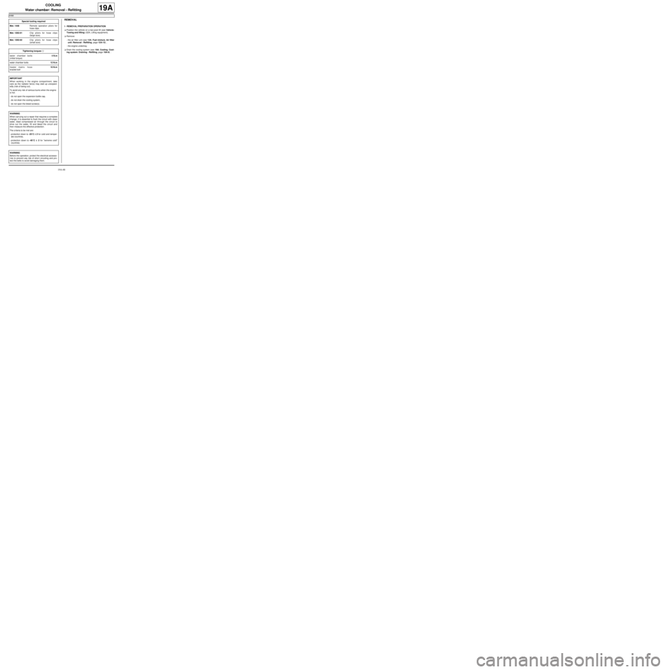
aUsing the (Mot. 1448) or (Mot. 1202-01) or (Mot.
1202-02) remove:
-the cooling radiator top hose clip on the water
chamber,
-the heater matrix hose clip (1) on the water cham-
ber.
aDisconnect from the water chamber:
-the cooling radiator top hose,
-the heater matrix hose.
aRemove:
-the bolt (2) from the heater matrix hose bracket,
-the heater matrix hose bracket,
-the bolts (3) of the engine wiring channel,
-the coolant temperature sensor (see 19A, Cool-
ing, Coolant temperature sensor: Removal - Re-
fitting, page 19A-66) .
aMove aside the engine wiring channel.
aUnclip the wiring at (4) .II - REMOVAL OPERATION
aRemove:
-the coolant outlet unit bolts,
-the water chamber,
-the water chamber seal.
REFITTING
I - REFITTING PREPARATION OPERATION
aparts always to be replaced: Cylinder head cool-
ant outlet unit seal.
aUse SURFACE CLEANER (see Vehicle: Parts
and consumables for the repair) (04B, Consuma-
bles - Products) to clean and degrease:
-the cylinder head joint face,
-the coolant outlet unit housing if it is being reused.
132444
128456
WARNING
The joint faces must be clean, dr y and free from
grease (avoid finger marks).