K4M RENAULT TWINGO RS 2009 2.G Engine And Peripherals Workshop Manual
[x] Cancel search | Manufacturer: RENAULT, Model Year: 2009, Model line: TWINGO RS, Model: RENAULT TWINGO RS 2009 2.GPages: 652
Page 508 of 652
17B-33
PETROL INJECTION
Injector rail - Injectors: Removal - Refitting
K4M
17B
REMOVAL
I - REMOVAL PREPARATION OPERATION
aDisconnect the battery (see ) (80A, Battery).
aRemove:
-the windscreen wiper arms (see Windscreen wip-
er arm: Removal - Refitting) (85A, Wiping -
Washing),
-the scuttle panel grille (see Scuttle panel grille:
Removal - Refitting) (56A, Exterior equipment),
-the scoop under the scuttle panel grille (see Scoop
under the scuttle panel grille: Removal - Refit-
ting) (56A, Exterior equipment).a
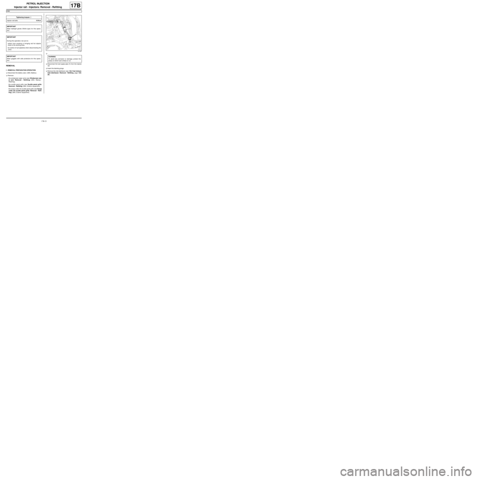
aDisconnect the fuel supply pipe (1) from the injector
rail.
aInsert the blanking plugs.
aRemove the inlet distributor (see 12A, Fuel mixture,
Inlet distributor: Removal - Refitting, page 12A-
29) . Tightening torquesm
injector rail bolts10 N.m
IMPORTANT
Wear leaktight gloves (Nitrile type) for this opera-
tion.
IMPORTANT
During this oper ation, be sure to:
-refrain from smoking or bringing red hot objects
close to the working area,
-be careful of fuel splashes when disconnecting the
union.
IMPORTANT
Wear goggles with side protectors for this opera-
tion.
131767
WARNING
To avoid any corrosion or damage, protect the
areas on which fuel is likely to r un.
Page 509 of 652
17B-34
PETROL INJECTION
Injector rail - Injectors: Removal - Refitting
K4M
17B
II - REMOVAL OPERATION
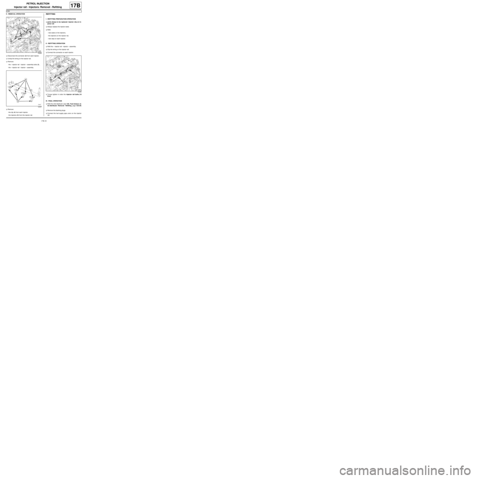
aDisconnect the connector (2) from each injector.
aUnclip the wiring on the injector rail.
aRemove:
-the « injector rail - injector » assembly bolts (3) ,
-the « injector rail - injector » assembly.
aRemove:
-the clip (4) from each injector,
-the injectors (5) from the injector rail.REFITTING
I - REFITTING PREPARATION OPERATION
aparts always to be replaced: injector clip on in-
jector rail.
aAlways replace the injector seals.
aRefit:
-new seals on the injectors,
-the injectors on the injector rail,
-new clips on each injector.
II - REFITTING OPERATION
aRefit the « injector rail - injector » assembly.
aClip the wiring on the injector rail.
aConnect the connector on each injector.
aTorque tighten in order the injector rail bolts (10
N.m).
III - FINAL OPERATION
aRefit the inlet distributor (see 12A, Fuel mixture, In-
let distributor: Removal - Refitting, page 12A-29)
.
aRemove the blanking plugs.
aConnect the fuel supply pipe union on the injector
rail.
132390
128397
132390
Page 510 of 652
17B-35
PETROL INJECTION
Injector rail - Injectors: Removal - Refitting
K4M
17B
aRefit:
-the scoop under the scuttle panel grille (see Scoop
under the scuttle panel grille: Removal - Refit-
ting) (56A, Exterior equipment),
-the scuttle panel grille (see Scuttle panel grille:
Removal - Refitting) (56A, Exterior equipment),
-the windscreen wiper arms (see Windscreen wip-
er arm: Removal - Refitting) (85A, Wiping -
Washing).
aConnect the battery (see ) (80A, Battery).
Page 511 of 652
19A-1
COOLING
Engine cooling system: Specifications
D4F or D7F or K4M or K9K
19A
Vehicles in the current range have cooling systems
with the following basic specifications:
-hermetically-sealed pressurised circuit (with expan-
sion bottle valve),
-circuit using only type « D » fluid,
-passenger compartment heating system equipped
with a « heater matrix » type radiator located under
the dashboard which helps to cool the engine.
Coolant quantities
Special notes:
-protection down to - 25˚C ±± ± ±
2 for cold and temperate
countries,
-protection down to - 40˚C ±± ± ±
2 for "extreme cold" coun-
tries.
Thermostat opening temperaturesEngine Quantity
(litres)Grade
D7F 800 5.5
Only use coolant
GLACEOL RX
(type D) D4F 772 5.5
K9K 740 5.7
D4F 780 5.7
D4F 782 5.7
K4M 854 5.7
Engine Star t o f
opening (˚C)Fully open (˚C)
D7F89 99
D4F89 99 ±± ± ±
2
K9K83 ±± ± ±
395
K4M89 101
Page 514 of 652
19A-4
COOLING
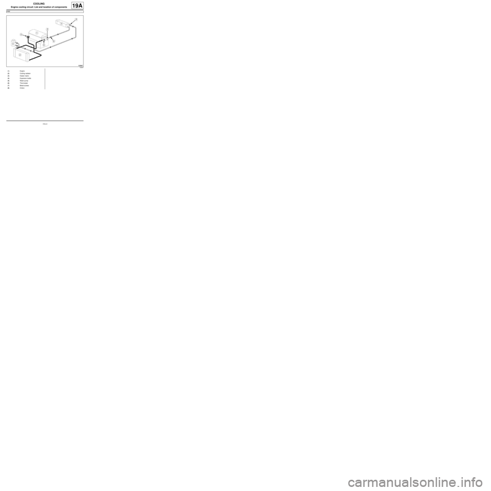
Engine cooling circuit: List and location of components
K4M
19A
132947
(1) Engine
(2) Cooling radiator
(3) Heater matrix
(4) Expansion bottle
(5) Water pump
(6) Thermostat
(7) Bleed screws
(8) Chok e
Page 518 of 652
19A-8
COOLING
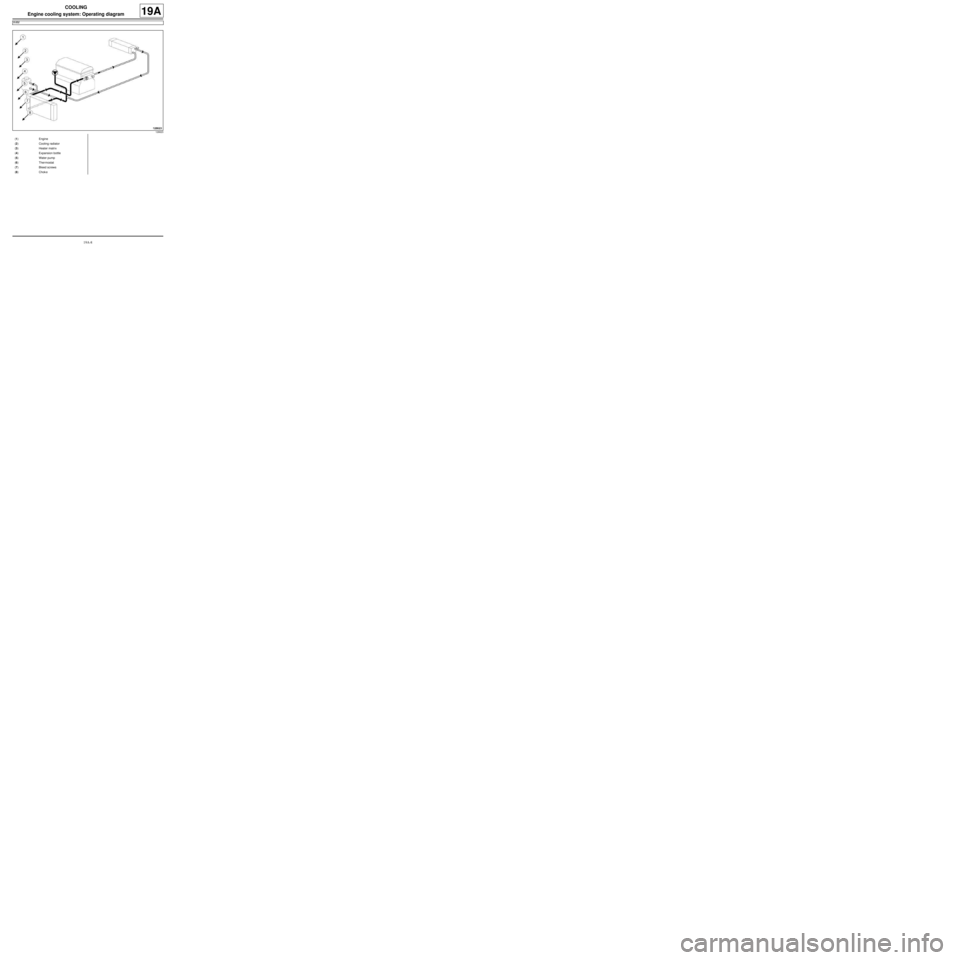
Engine cooling system: Operating diagram
K4M
19A
128623
(1) Engine
(2) Cooling radiator
(3) Heater matrix
(4) Expansion bottle
(5) Water pump
(6) Thermostat
(7) Bleed screws
(8) Chok e
Page 519 of 652
19A-9
COOLING
Cooling system: Draining - Refilling
D4F or D7F or K4M or K9K
19A
a
I - DRAINING
aPosition the vehicle on a two-post lift (see Vehicle:
Towing and lifting) (02A, Lifting equipment).
aRemove the expansion bottle cap.aRemove the engine undertray.
aPosition the coolant recovery tray under the vehi-
cle.
aRemove the cooling radiator bottom hose clip using
the tool (Mot. 1202-01) or (Mot. 1202-02) or (Mot.
1448).
aOpen the cooling system by removing the cooling ra-
diator bottom hose using the tool (Car. 1363).
aUse a compressed air nozzle to blow air into the
system through the expansion bottle opening to re-
move as much coolant as possible.
II - CLEANING
aFill the cooling system with water through the expan-
sion bottle.
aLet the water run until the water collected by the
cooling radiator bottom hose becomes clear.
aUse a compressed air nozzle to blow air into the
circuit through the expansion bottle opening to re-
move as much water as possible.
aRefit the hose which was removed.
III - FILLING
a
1 - Filling procedure with the tool (Mot. 1700)
aFill the cooling system with engine coolant recom-
mended by the manufacturer (see Vehicle: Parts
and consumables for the repair) (04B, Consum-
ables - Products) using the tool (Mot. 1700).
For the use of this tool (see Cooling system filling
and diagnostic tool: Use) (NT 3857A, 19A, Cool-
ing). Special tooling required
Mot. 1202-01Clip pliers for hose clips
(large size).
Mot. 1202-02Clip pliers for hose clips
(small size)
Mot. 1448Remote operation pliers for
hose clips .
Car. 1363Set of tr im removal levers.
Mot. 1700Fault finding and filling -
bleeding the cooling circuit.
Ms. 554-07Instr ument for testing the
cooling circuit and the expan-
sion bottle valve. Contains
caps 554-01, 554-04, 554-06
Equipment required
coolant recovery tray
compressed air nozzle
pedal press
IMPORTANT
When working in the engine compartment, take
care as the radiator fan(s) may start up unex-
pectedly (risk of being cut).
To avoid any risk of serious burns when the
engine is hot:
-do not open the expansion bottle cap,
-do not dr ain the cooling system,
-do not open the bleed screw(s).
WARNING
Before the operation, protect the electrical acces-
sories to prevent any risk of short circuiting and
protect the belts to avoid damaging them.
K4M
Note:
There are two procedures for filling the cooling
system:
-the method using the (Mot. 1700) tool is recom-
mended by Renault. It saves a considerable
amount of time because it does not require the
cooling system bleed screws to be opened,
-the procedure without a special tool.
Page 520 of 652
19A-10
COOLING
Cooling system: Draining - Refilling
D4F or D7F or K4M or K9K
19A
2 - Filling method without special tools
a
aRemove the air filter unit (see 12A, Fuel mixture,
Air filter unit: Removal - Refitting, page 12A-13) .
aRemove the front engine cover.
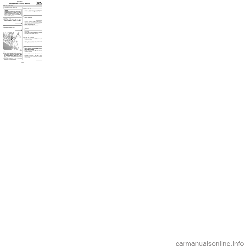
aOpen the bleed screws (1) and (2) .
aFill the cooling system with engine coolant recom-
mended by the manufacturer (see Vehicle: Parts
and consumables for the repair) (04B, Consum-
ables - Products) via the expansion bottle until it
overflows.
aClose all the bleed screws as soon as the coolant
starts to flow in a continuous stream.aRefit the air filter unit (see 12A, Fuel mixture, Air fil-
ter unit: Removal - Refitting, page 12A-13) .
aRefit the engine cover.
aPressurise the system using the (Ms. 554-07) to
check that there are no leaks (see 19A, Cooling,
Engine cooling system: Check, page 19A-2) .
aRefit the expansion bottle cap.
aClean any surfaces soiled by the coolant.
IV - BLEEDING
a
aStart the engine.
aMaintain the engine speed at 2500 rpm using the
pedal press for 5 min.
aStabilise the engine speed at 2000 rpm until the fan
assembly has been activated twice.
aMaintain the engine speed at 2500 rpm, using the
pedal press for 5 minutes.
aStabilise the engine speed at 2000 rpm until the fan
assembly is activated.
aNote the coolant level in the expansion bottle after
this first activation.
aAccelerate at a minimum of 4000 rpm for several
seconds, until the level of coolant fluid in the expan-
sion bottle drops. WARNING
It is essential to open all of the bleed screws to
remove as much as air as possible in the cooling
system. Failure to perform this procedure may
prevent the cooling system from filling properly
and may damage the engine.
D4F, and 772 – K4M
K9K
120526
D4F, and 772 – K4M
K9K
WARNING
Do not open the bleed screw whilst the engine is
running; this would damage the engine.
D4F, and 772 – D7F, and 800
D4F, and 780 or 782
Page 521 of 652
19A-11
COOLING
Cooling system: Draining - Refilling
D4F or D7F or K4M or K9K
19A
aMaintain the engine speed at 1500 rpm, sharply
varying the engine speed (up to the maximum) 2 to
3 times approximately every 2 minutes until the fan
assembly starts for the second time.
aMaintain the engine speed at 3000 rpm using a ped-
al press, until the fan assembly has been activated
for a third time.
aCheck that the heating is operating correctly.
aAllow the engine to cool until the engine coolant tem-
perature is less than 50˚C.
aRemove the expansion bottle cap.
aAdjust the coolant fluid level to the "Max" mark.
aRefit the expansion bottle cap.
V - FINAL OPERATION
aRemove the coolant recovery tray.
aRefit the engine undertray. K9K
K4M
K4M
Page 530 of 652
19A-20
COOLING
Cooling radiator: Removal - Refitting
K4M
19A
REMOVAL
I - REMOVAL PREPARATION OPERATION
aPosition the vehicle on a two-post lift (see Vehicle:
Towing and lifting) (02A, Lifting equipment).
aDisconnect the battery (see Battery: Removal - Re-
fitting) (80A, Battery).
aDrain the air conditioning circuit using a refrigerant
charging station (see Refrigerant circuit: Drain-
ing - Filling) (62A, Air conditioning).
aRemove:
-the engine undertray bolts,
-the engine undertray,
-the front wheels (see Wheel: Removal - Refitting)
(35A, Wheels and tyres),
-the front wheel arch liners (see Front wheel arch
liner: Removal - Refitting) (55A, Exterior protec-
tion),
-the front bumper (see Front bumper: Removal -
Refitting) (55A, Exterior protection).
aDrain the cooling system (see 19A, Cooling, Cool-
ing system: Draining - Refilling, page 19A-9) . Special tooling required
Mot. 1448Remote operation pliers for
hose clips .
Equipment required
refrigerant charging station
safety strap(s)
Tightening torquesm
bolt of the dehydrator
reservoir - « expansion
valve connecting pipe » 8 N.m
compressor - con-
denser « connecting
pipe bolt » 8 N.m
air conditioning connect-
ing pipe bolts8 N.m
IMPORTANT
When working in the engine compartment, take
care as the radiator fan(s) may start up unexpect-
edly (risk of being cut).
To avoid any risk of serious burns when the engine
is hot:
-do not open the expansion bottle cap,
-do not drain the cooling system,
-do not open the bleed screw(s).
WARNING
Prepare for the flow of fluid, and protect the sur-
rounding components.
WARNING
When carr ying out a repair that requires a complete
change, it is essential to flush the circuit with clean
water, blast compressed air through the circuit to
drive out the water, fill and bleed the circuit and
then measure the effective protection.
The cr iteria to be met are:
-protection down to -25˚C ±± ± ±
2 for cold and temper-
ate countries,
-protection down to -40˚C ±± ± ±
2 for "extreme cold"
countries.