RENAULT TWINGO RS 2009 2.G Panelwork Repair Manual
TWINGO RS 2009 2.G
RENAULT
RENAULT
https://www.carmanualsonline.info/img/7/1724/w960_1724-0.png
RENAULT TWINGO RS 2009 2.G Panelwork Repair Manual
Trending: dashboard warning lights, headlight, warning light, headlights, brake, spare wheel, engine
Page 51 of 209
41A-12
FRONT LOWER STRUCTURE
Front side member closure panel, front section: General description41A
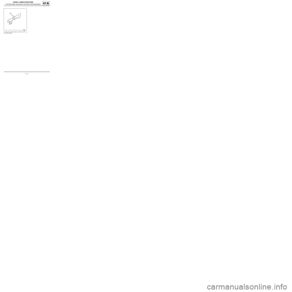
Line (3) on the drawing shows a butt weld by conti-
nuous EGW welding.
110554
Page 52 of 209
41A-13
FRONT LOWER STRUCTURE
Front side member closure panel, front section: Description41A
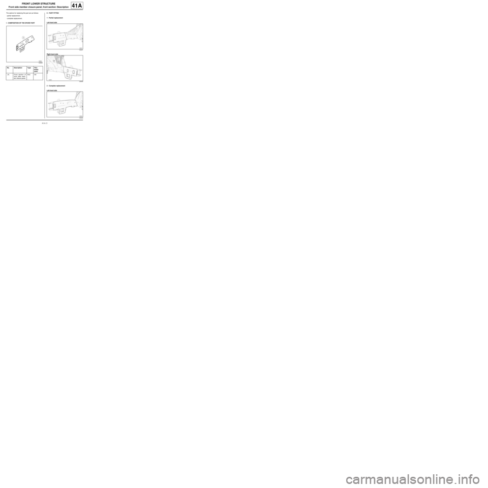
The options for replacing this part are as follows:
-partial replacement,
-complete replacement.
I - COMPOSITION OF THE SPARE PARTII - PART FITTED
1 - Partial replacement
Left-hand side
Right-hand side
2 - Complete replacement
Left-hand side
120638
No. Description Type Thic-
kness
(mm)
(1) Front section of
front side mem-
ber closure panelHLE1.4
120641
120639
120642
Page 53 of 209
41A-14
FRONT LOWER STRUCTURE
Front side member closure panel, front section: Description41A
Right-hand side
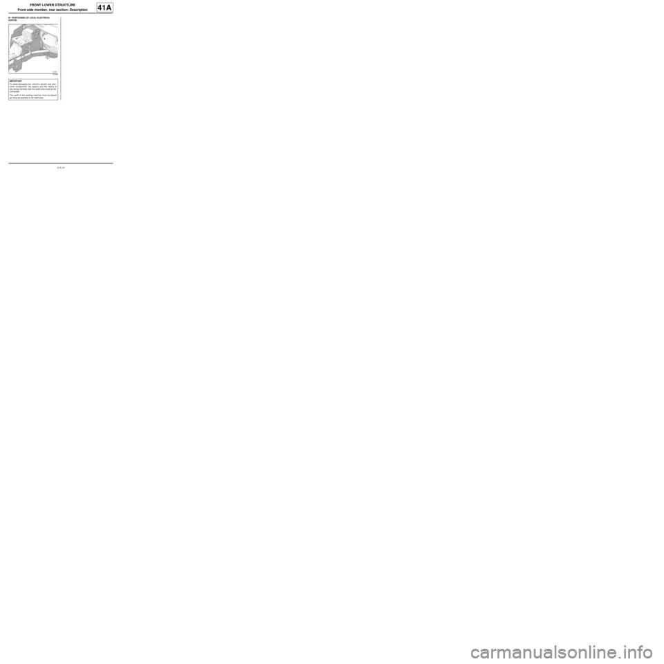
III - POSITIONING OF LOCAL ELECTRICAL
EARTHS
120640
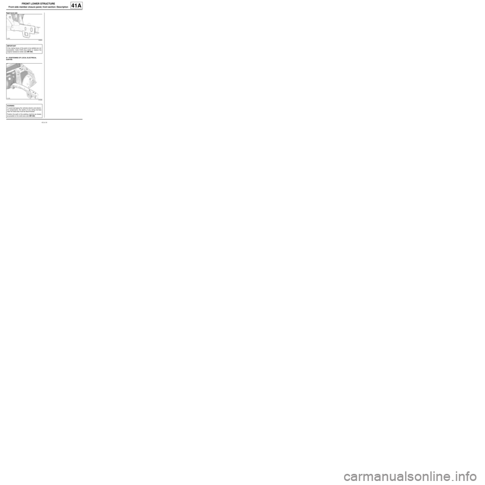
IMPORTANT
If the mating faces of the parts to be welded are not
accessible, make EGW plug welds to replace the
original resistance welds (see MR 400).
121245
WARNING
To avoid damaging the vehicles electric and electro-
nic components, the earths of any wiring harness
near the weld area must be disconnected.
Position the earth of the welding machine as closely
as possible to the weld area (see MR 400).
Page 54 of 209
41A-15
FRONT LOWER STRUCTURE
Front side member, rear section: Description
41A
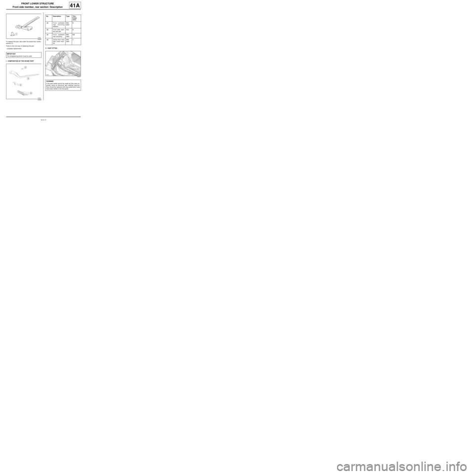
To replace this part, also order the centre floor reinfor-
cement (1) .
There is only one way of replacing this part:
-complete replacement.
I - COMPOSITION OF THE SPARE PARTII - PART FITTED
120635
IMPORTANT
The straightening bench must be used.
120636
No. Description Type Thic-
kness
(mm)
(2) Front subframe
rear mounting
stiffenerMild
steel2
(3) Front side mem-
ber rear partHLE2
(4) Front subframe
rear mountingMild
steel2.5
(5) Centre floor front
side cross mem-
berMild
steel1
120637
WARNING
If the spot welds cannot be made as they were ori-
ginally using an electrical spot welding machine,
they should be replaced with plug welds after holes
have been drilled in the first panel.
Page 55 of 209
41A-16
FRONT LOWER STRUCTURE
Front side member, rear section: Description
41A
III - POSITIONING OF LOCAL ELECTRICAL
EARTHS
121246
IMPORTANT
To avoid damaging the vehicle's electric and elec-
tronic components, the battery and the earths of
any wiring harness near the weld area must be dis-
connected.
The earth of the welding machine must be placed
as close as possible to the weld area.
Page 56 of 209
41A-17
FRONT LOWER STRUCTURE
Front subframe front mounting: General description
41A
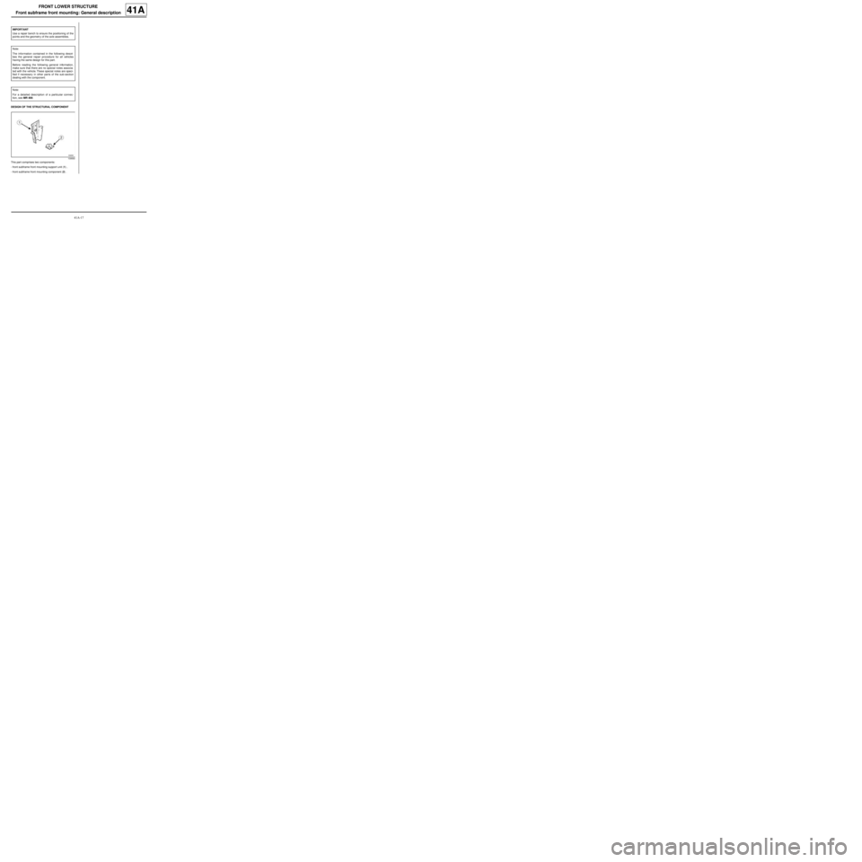
DESIGN OF THE STRUCTURAL COMPONENT
This part comprises two components:
-front subframe front mounting support unit (1) ,
-front subframe front mounting component (2) . IMPORTANT
Use a repair bench to ensure the positioning of the
points and the geometr y of the axle assemblies.
Note:
The information contained in the following descri-
bes the general repair procedure for all vehicles
having the same design for this part.
Before reading the following general information,
make sure that there are no special notes associa-
ted with the vehicle. These special notes are speci-
fied if necessary in other par ts of the sub-section
dealing with the component.
Note:
For a detailed description of a particular connec-
tion, see MR 400.
109560
Page 57 of 209
41A-18
FRONT LOWER STRUCTURE
Front subframe front mounting: Description
41A
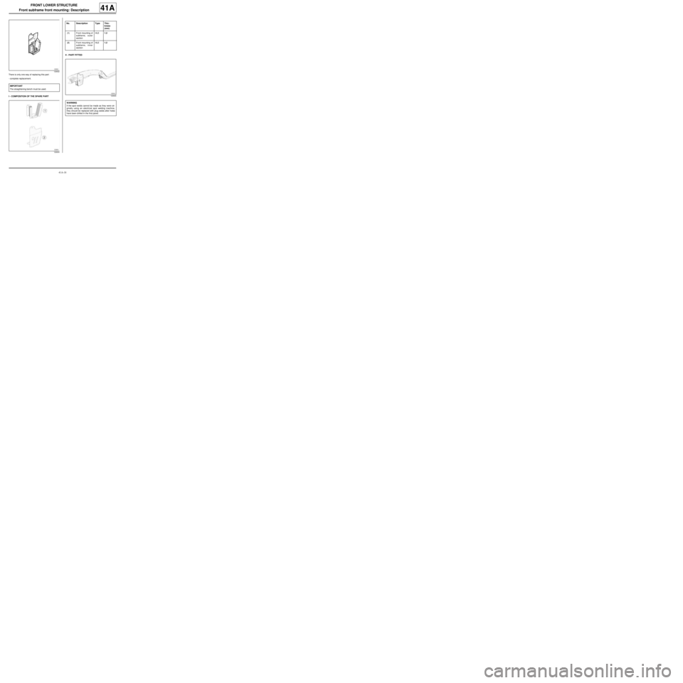
There is only one way of replacing this part:
-complete replacement.
I - COMPOSITION OF THE SPARE PARTII - PART FITTED
120632
IMPORTANT
The straightening bench must be used.
120634
No. Description Type Thic-
kness
(mm)
(1) Front mounting of
subframe, outer
sectionHLE1.2
(2) Front mounting of
subframe, inner
sectionHLE1.2
120633
WARNING
If the spot welds cannot be made as they were ori-
ginally using an electrical spot welding machine,
they should be replaced with plug welds after holes
have been drilled in the first panel.
Page 58 of 209
41A-19
FRONT LOWER STRUCTURE
Front subframe front mounting: Description
41A
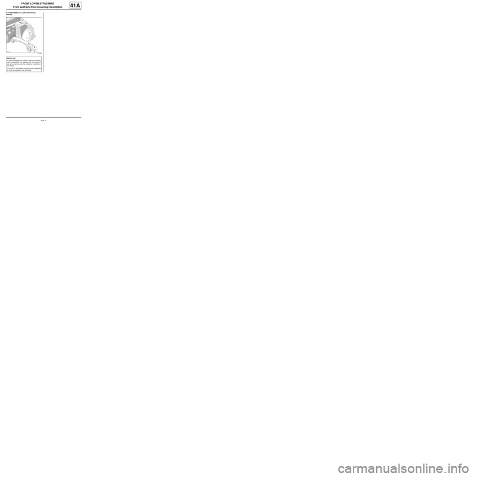
III - POSITIONING OF LOCAL ELECTRICAL
EARTHS
121245
IMPORTANT
To avoid damaging the vehicle's electric and elec-
tronic components, the battery and the earths of
any wiring harness near the weld area must be dis-
connected.
The earth of the welding machine must be placed
as close as possible to the weld area.
Page 59 of 209
41A-20
FRONT LOWER STRUCTURE
Engine stand: General description
41A
DESIGN OF THE STRUCTURAL COMPONENT
This is a basic part; it only functions as an engine
mounting.IMPORTANT
Use a repair bench to ensure the positioning of the
points and the geometr y of the axle assemblies.
Note:
The information contained in the following descri-
bes the general repair procedure for all vehicles
having the same design for this part.
Before reading this general information, check that
there are no special notes associated with this vehi-
cle. These special notes will be specified if applica-
ble in other parts of this subsection dealing with the
par t.
Note:
For a detailed description of a particular connec-
tion, see MR 400.
110557
Page 60 of 209
41A-21
FRONT LOWER STRUCTURE
Engine stand: Description
41A
There is only one way of replacing this part:
-complete replacement.
I - COMPOSITION OF THE SPARE PARTII - PART FITTED
120626
IMPORTANT
The straightening bench must be used.
120627
No. Description Type Thic-
kness
(mm)
(1) E ngine support
plateMild
steel2
(2) Engine mounting
height adjusterMild
steel1.8
(3) Engine height
adjuster stiffenerHLE2
120628
WARNING
If the spot welds cannot be made as they were ori-
ginally using an electrical spot welding machine,
they should be replaced with plug welds after holes
have been drilled in the first panel.
Trending: door lock, sunroof, wiring, fuel, coolant, open bonnet, gas type
