SKODA FABIA 2014 2.G / 5J Workshop Manual
Manufacturer: SKODA, Model Year: 2014, Model line: FABIA, Model: SKODA FABIA 2014 2.G / 5JPages: 197, PDF Size: 13.56 MB
Page 51 of 197
In addition, when the car is unlocked, the electrically adjustable seats and ex-
terior mirrors move into the position assigned to this key. The stored setting of
driver seat and exterior mirrors is retrieved.
Locking
The turn signal lights flash once to confirm that the vehicle has been correctly
locked.
If the doors or the boot lid remain open after the vehicle has been locked, the
turn signal lights do not flash until they have been closed.
Note
■ Only operate the remote control when the doors and boot lid are closed and
the vehicle is in your line of sight.■
A ŠKODA partner can also activate/deactivate the acoustic signals on vehi-
cles with an anti-theft alarm system.
Synchronization
If the vehicle does not unlock when the remote control is pressed, the key may
not be synchronised. This can occur when the buttons on the remote control
key are pressed several times outside the operating range of the equipment or
if the battery in the remote control key has been replaced.
Synchronise the key as follows.
›
Press any button on the remote control key.
›
Unlock the door with the key within 1 minute of pressing the button.
Anti-theft alarm system
Introduction
This chapter contains information on the following subjects:
Operation
49
Interior monitor and towing protection
50
The anti-theft alarm system increases the level of protection against people
seeking to break into the vehicle. The system triggers audible and visual warn-
ing signals if an attempt is made to break into the vehicle.
Note■ The working life of the alarm siren is 5 years.■Before leaving the car, it must be checked that all of the windows, doors and
the electric sliding/tilting roof are properly closed to ensure the full functional-
ity of the anti-theft alarm system.■
Coding of the radio remote control and the receiver unit precludes the use of
the radio remote control from other vehicles.
Operation
How is the alarm system activated?
The anti-theft alarm system is activated when the vehicle is locked with the
radio remote control or the key in the driver's door . It is activated 30 seconds
after locking the door.
How is the alarm system deactivated?
The alarm system is deactivated by pressing the button on the remote con-
trol. The anti-theft alarm system is reactivated if the vehicle is not opened
within 30 seconds after transmitting the radio signal.
Triggering the alarm
The alarm is triggered when the following unauthorized actions are carried out
on the locked vehicle.
› Opening the bonnet.
› Opening the boot lid.
› Opening the doors.
› Manipulation of the ignition lock.
› Towing the vehicle
» page 50;
› Movement in the vehicle
» page 50.
› Sudden and significant voltage drop of the electrical system.
› Uncoupling the trailer
» page 125.
If the driver's door of a vehicle with a remote control is unlocked and opened
by the lock cylinder, then the alarm is triggered.
Switching off the alarm
The alarm is turned off by pressing the button on the radio remote control
key or switching on the ignition.
CAUTION
Before leaving the vehicle, it must be checked that all of the windows, doors
and the sliding/tilting roof are locked in order to ensure the full functionality of
the anti-theft alarm system.49Unlocking and locking
Page 52 of 197
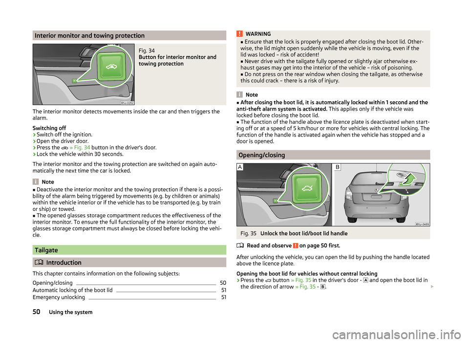
Interior monitor and towing protectionFig. 34
Button for interior monitor and
towing protection
The interior monitor detects movements inside the car and then triggers the
alarm.
Switching off
›
Switch off the ignition.
›
Open the driver door.
›
Press the
» Fig. 34 button in the driver's door.
›
Lock the vehicle within 30 seconds.
The interior monitor and the towing protection are switched on again auto-
matically the next time the car is locked.
Note
■ Deactivate the interior monitor and the towing protection if there is a possi-
bility of the alarm being triggered by movements (e.g. by children or animals)
within the vehicle interior or if the vehicle has to be transported (e.g. by train
or ship) or towed.■
The opened glasses storage compartment reduces the effectiveness of the
interior monitor. To ensure the full functionality of the interior monitor, the
glasses storage compartment must always be closed before locking the vehi-
cle.
Tailgate
Introduction
This chapter contains information on the following subjects:
Opening/closing
50
Automatic locking of the boot lid
51
Emergency unlocking
51WARNING■ Ensure that the lock is properly engaged after closing the boot lid. Other-
wise, the lid might open suddenly while the vehicle is moving, even if the
lid was locked – risk of accident!■
Never drive with the tailgate fully opened or slightly ajar otherwise ex-
haust gases may get into the interior of the vehicle – risk of poisoning.
■
Do not press on the rear window when closing the tailgate, as otherwise
this could crack – there is a risk of injury.
Note
■ After closing the boot lid, it is automatically locked within 1 second and the
anti-theft alarm system is activated. This applies only if the vehicle was
locked before closing the boot lid.■
The function of the handle above the licence plate is deactivated when start-
ing off or at a speed of 5 km/hour or more for vehicles with central locking. The
function of the handle is activated again when the vehicle has stopped and a
door is opened.
Opening/closing
Fig. 35
Unlock the boot lid/boot lid handle
Read and observe
on page 50 first.
After unlocking the vehicle, you can open the lid by pushing the handle located
above the licence plate.
Opening the boot lid for vehicles without central locking
›
Press the
button » Fig. 35 in the driver's door -
and open the boot lid in
the direction of arrow » Fig. 35 -
.
50Using the system
Page 53 of 197
Opening the boot lid for vehicles with central locking›Press the handle and open the tailgate in the direction of the arrow » Fig. 35
-
.
Closing›
Pull down the tailgate and close it with a gentle swing.
A handle which makes the closing easier is located on the inner panelling of
the boot lid.
Automatic locking of the boot lid
Read and observe
on page 50 first.
If the boot lid is unlocked with the key symbol on the remote control key,
then the door is automatically locked after closing.
The period after which the boot lid is locked automatically can be extended by
a specialist garage.
After the activation of the delayed locking, the door can be opened again after
closing within a limited period.
Delayed locking can be deactivated by a specialist garage at any time.
CAUTION
There is a risk of unwanted entry into the vehicle before the boot lid is locked
automatically. We therefore recommend locking the vehicle with the key sym-
bol
on the remote control key.
Emergency unlocking
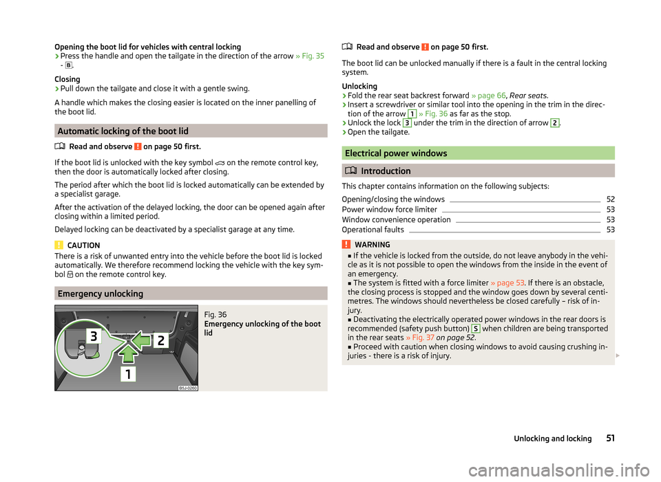
Fig. 36
Emergency unlocking of the boot
lid
Read and observe on page 50 first.
The boot lid can be unlocked manually if there is a fault in the central locking
system.
Unlocking
›
Fold the rear seat backrest forward » page 66, Rear seats .
›
Insert a screwdriver or similar tool into the opening in the trim in the direc-
tion of the arrow
1
» Fig. 36 as far as the stop.
›
Unlock the lock
3
under the trim in the direction of arrow
2
.
›
Open the tailgate.
Electrical power windows
Introduction
This chapter contains information on the following subjects:
Opening/closing the windows
52
Power window force limiter
53
Window convenience operation
53
Operational faults
53WARNING■ If the vehicle is locked from the outside, do not leave anybody in the vehi-
cle as it is not possible to open the windows from the inside in the event of
an emergency.■
The system is fitted with a force limiter » page 53. If there is an obstacle,
the closing process is stopped and the window goes down by several centi-
metres. The windows should nevertheless be closed carefully – risk of in-
jury.
■
Deactivating the electrically operated power windows in the rear doors is
recommended (safety push button)
S
when children are being transported
in the rear seats » Fig. 37 on page 52 .
■
Proceed with caution when closing windows to avoid causing crushing in-
juries - there is a risk of injury.
51Unlocking and locking
Page 54 of 197
CAUTION■Keep the windows clean to ensure the correct functionality of the electric
windows.■
Should the windows freeze, first remove the ice » page 131, Windows and
exterior mirrors and only then operate the power windows. Otherwise, the
window seal and the power window mechanism could be damaged.
■
In the winter, ice on the window may cause greater resistance as the win-
dow is closed. The window will stop and open again by several centimetres.
■
Always make sure that the windows are closed when you leave the locked
vehicle.
For the sake of the environment
At high speeds, you should keep the windows closed to prevent unnecessarily high fuel consumption.
Note
■ After switching the ignition off, it is still possible to open or close the win-
dows for approx. 10 minutes. After the driver's or front passenger's door has
been opened, the windows can only be operated by using A
» Fig. 37 on
page 52 .
■
When driving always use the existing heating, air conditioning and ventila-
tion system for ventilating the interior of the vehicle. If the windows are
opened, dust as well as other dirt can get into the vehicle and in addition the
wind noise is more at certain speeds.
Opening/closing the windows
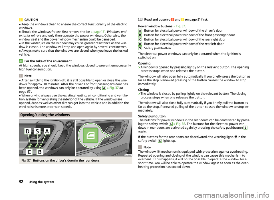
Fig. 37
Buttons on the driver's door/in the rear doors
Read and observe and on page 51 first.
Power window buttons » Fig. 37 .
Button for electrical power window of the driver's door
Button for electrical power window of the front passenger door
Button for electrical power window of the rear right door
Button for electrical power window of the rear left door
Safety pushbutton
The electrical power windows can only be operated when the ignition is
switched on.
Opening
›
A window is opened by pressing lightly on the relevant button. The opening
process stops when one releases the button.
The window will also open fully automatically if you briefly press the button as
far as the stop. Renewed pressing of the button causes the window to stop
immediately.
Closing
›
The window is closed by pulling lightly on the relevant button. The closing
process stops when one releases the button.
The window will also close fully automatically if you briefly pull the button as
far as the stop. Renewed pulling of the button causes the window to stop im-
mediately.
Safety pushbutton
The buttons for power windows in the rear doors can be deactivated by press-
ing the safety switch
S
» Fig. 37 . The buttons for the electrical power win-
dows in rear doors are activated again by pressing the safety pushbutton
S
again.
If the buttons for the rear doors are deactivated, the warning light in the
safety switch
S
lights up.
Note
The window lift mechanism is equipped with protection against overheating.
Repeated opening and closing of the window can cause this mechanism to
overheat. If this happens, it will not be possible to operate the window for a
short time. You will be able to operate the window again as soon as the over-
heating protection has cooled down.ABCDS52Using the system
Page 55 of 197
Power window force limiterRead and observe
and on page 51 first.
The electrical power windows are fitted with a force limiter. It reduces the risk
of bruises or injuries when closing the windows.
If there is an obstacle, the closing process is stopped and the window goes
down by several centimetres.
If the obstacle prevents the window from being closed during the next 10 sec-
onds, the closing process is interrupted once again and the window goes down
by several centimetres.
If you attempt to close the window again within 10 seconds of the window be-
ing moved down for the second time, even though the obstacle was not yet
been removed, the closing process is only stopped. During this time it is not
possible to automatically close the window. The force limiter is still switched
on.
The force limiter is only switched off if you attempt to close the window again
within the next 10 seconds - the window will now close with full force!
If you wait longer than 10 seconds, the force limiter is switched on again.
Window convenience operation
Read and observe
and on page 51 first.
The comfort controls of the windows provide the ability to open or close all the
windows at once.
Opening can take place in one of the following ways.
Opening
›
Press the symbol button on the remote control key and hold.
›
Hold the key in the driver's lock in the unlock position.
›
Hold button
A
» Fig. 37 on page 52 in the opening position.
Closing
›
Press the symbol button on the remote control key and hold.
›
Hold the key in the driver's lock in the lock position.
›
Hold Button
A
» Fig. 37 on page 52 in the closing position.
The movement of the window is immediately stopped by releasing the key or
the respective button.
Operational faults
Read and observe
and on page 51 first.
Electrical power windows do not operate
If the battery has been disconnected and then reconnected while the window was opened, the electrical power windows will not operate. The system must
be activated. Proceed as follows to re-establish the function.
› Switch on the ignition.
› Pull the top edge of the button in the driver's door and close the window.
› Release the button.
› Pull the relevant button upwards again for another approximately 3 seconds
and hold.
Operation in winter
In the winter, ice on the window may cause greater resistance as the window
is closed. The window will stop and open again by several centimetres.
It is necessary to deactivate the force limiter to close the window » page 53.
Electric sliding/tilting roof
Introduction
This chapter contains information on the following subjects:
Operation
54
Comfort operation
54
Emergency operation
55
The sliding/tilting roof is operated with the rotary switch » Fig. 38 on
page 54 and only works when the ignition is switched on. The control dial
has several positions.
The sliding/tilting roof can still be opened, closed and tilted for approx. 10 mi-
nutes after switching the ignition off. However, as soon as one of the front
doors is opened it is no longer possible to operate the sliding/tilting roof.
WARNINGClose the sliding/tilting roof carefully – risk of injury. 53Unlocking and locking
Page 56 of 197
CAUTIONDuring the winter it may be necessary to remove any ice and snow in the vicin-
ity of the sliding/tilting roof before opening it to prevent any damage to the
opening mechanism and seal.
Note
If the battery has been disconnected and reconnected, it is possible that the
sliding/tilting roof does not close fully. This is why the rotary switch must be
set to position A
» Fig. 38 on page 54 and pressed forwards for about
10 seconds.
Operation
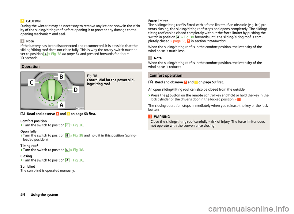
Fig. 38
Control dial for the power slid-
ing/tilting roof
Read and observe and on page 53 first.
Comfort position
›
Turn the switch to position
C
» Fig. 38 .
Open fully
›
Turn the switch to position
B
» Fig. 38 and hold it in this position (spring-
loaded position).
Tilting roof
›
Turn the switch to position
D
» Fig. 38 .
Closing
›
Turn the switch to position
A
» Fig. 38 .
Sun blind
The sun blind is operated manually.
Force limiter
The sliding/tilting roof is fitted with a force limiter. If an obstacle (e.g. ice) pre-
vents closing, the sliding/tilting roof stops and opens completely. The sliding/
tilting roof can be closed completely without the force limiter by pushing the
switch in position A
» Fig. 38 forwards until the sliding/tilting roof is com-
pletely closed » page 53, in section Introduction .
When the sliding/tilting roof is in the comfort position, the intensity of the
wind noise is much less.
Note
When the sliding/tilting roof is in the comfort position, the intensity of the
wind noise is reduced.
Comfort operation
Read and observe
and on page 53 first.
An open sliding/tilting roof can also be closed from the outside.
›
Press the button on the remote control key and hold or hold the key in the
lock cylinder of the driver's door in the locked position » .
The closing operation stops immediately when you release the key or the lock
button.
WARNINGClose the sliding/tilting roof carefully – risk of injury. The force limiter does
not operate with the convenience closing.54Using the system
Page 57 of 197
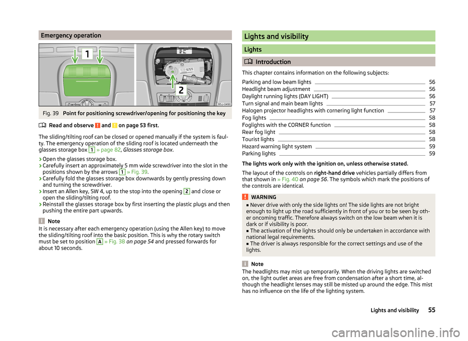
Emergency operationFig. 39
Point for positioning screwdriver/opening for positioning the key
Read and observe
and on page 53 first.
The sliding/tilting roof can be closed or opened manually if the system is faul-
ty. The emergency operation of the sliding roof is located underneath the
glasses storage box
1
» page 82 , Glasses storage box .
›
Open the glasses storage box.
›
Carefully insert an approximately 5 mm wide screwdriver into the slot in the
positions shown by the arrows
1
» Fig. 39 .
›
Carefully fold the glasses storage box downwards by gently pressing down
and turning the screwdriver.
›
Insert an Allen key, SW 4, up to the stop into the opening
2
and close or
open the sliding/tilting roof.
›
Reinstall the glasses storage box by first inserting the plastic plugs and then
pushing the entire part upwards.
Note
It is necessary after each emergency operation (using the Allen key) to move
the sliding/tilting roof into the basic position. This is why the rotary switch
must be set to position A
» Fig. 38 on page 54 and pressed forwards for
about 10 seconds.
Lights and visibility
Lights
Introduction
This chapter contains information on the following subjects:
Parking and low beam lights
56
Headlight beam adjustment
56
Daylight running lights (DAY LIGHT)
56
Turn signal and main beam lights
57
Halogen projector headlights with cornering light function
57
Fog lights
58
Foglights with the CORNER function
58
Rear fog light
58
Tourist lights
58
Hazard warning light system
59
Parking lights
59
The lights work only with the ignition on, unless otherwise stated.
The layout of the controls on right-hand drive vehicles partially differs from
that shown in » Fig. 40 on page 56 . The symbols which mark the positions of
the controls are identical.
WARNING■ Never drive with only the side lights on! The side lights are not bright
enough to light up the road sufficiently in front of you or to be seen by oth-
er oncoming traffic. Therefore always switch on the low beam when it is
dark or if visibility is poor.■
The activation of the lights should only be undertaken in accordance with
national legal requirements.
■
The driver is always responsible for the correct settings and use of the
lights.
Note
The headlights may mist up temporarily. When the driving lights are switched
on, the light outlet areas are free from condensation after a short time, al-
though the headlight lenses may still be misted up around the edge. This mist
has no influence on the life of the lighting system.55Lights and visibility
Page 58 of 197
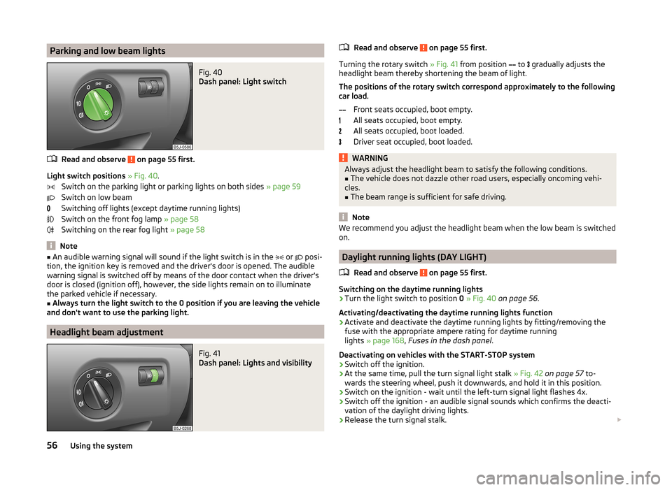
Parking and low beam lightsFig. 40
Dash panel: Light switch
Read and observe on page 55 first.
Light switch positions » Fig. 40 .
Switch on the parking light or parking lights on both sides » page 59
Switch on low beam
Switching off lights (except daytime running lights)
Switch on the front fog lamp » page 58
Switching on the rear fog light » page 58
Note
■
An audible warning signal will sound if the light switch is in the or posi-
tion, the ignition key is removed and the driver's door is opened. The audible
warning signal is switched off by means of the door contact when the driver's
door is closed (ignition off), however, the side lights remain on to illuminate
the parked vehicle if necessary.■
Always turn the light switch to the 0 position if you are leaving the vehicle
and don't want to use the parking light.
Headlight beam adjustment
Fig. 41
Dash panel: Lights and visibility
Read and observe on page 55 first.
Turning the rotary switch » Fig. 41 from position
to
gradually adjusts the
headlight beam thereby shortening the beam of light.
The positions of the rotary switch correspond approximately to the following
car load.
Front seats occupied, boot empty.
All seats occupied, boot empty.
All seats occupied, boot loaded.
Driver seat occupied, boot loaded.
WARNINGAlways adjust the headlight beam to satisfy the following conditions.■The vehicle does not dazzle other road users, especially oncoming vehi-
cles.■
The beam range is sufficient for safe driving.
Note
We recommend you adjust the headlight beam when the low beam is switched
on.
Daylight running lights (DAY LIGHT)
Read and observe
on page 55 first.
Switching on the daytime running lights
›
Turn the light switch to position 0 » Fig. 40 on page 56 .
Activating/deactivating the daytime running lights function
›
Activate and deactivate the daytime running lights by fitting/removing the
fuse with the appropriate ampere rating for daytime running
lights » page 168 , Fuses in the dash panel .
Deactivating on vehicles with the START-STOP system
›
Switch off the ignition.
›
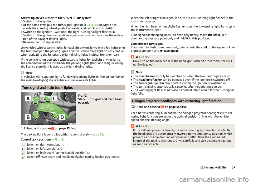
At the same time, pull the turn signal light stalk » Fig. 42 on page 57 to-
wards the steering wheel, push it downwards, and hold it in this position.
›
Switch on the ignition - wait until the left-turn signal light flashes 4x.
›
Switch off the ignition - an audible signal sounds which confirms the deacti-
vation of the daylight driving lights.
›
Release the turn signal stalk.
56Using the system
Page 59 of 197
Activating on vehicles with the START-STOP system›Switch off the ignition.›
At the same time, pull the turn signal light stalk » Fig. 42 on page 57 to-
wards the steering wheel, push it upwards, and hold it in this position.
›
Switch on the ignition - wait until the right-turn signal light flashes 4x.
›
Switch off the ignition - an audible signal sounds which confirms the activa-
tion of the daylight driving lights.
›
Release the turn signal stalk.
On vehicles with separate lights for daylight driving lights in the fog lights or in
the front bumper, the parking lights and the licence plate light do not come on
when activating the function daylight driving lights (neither front nor rear).
If the vehicle is not equipped with separate lights for daylight driving lights,
the combination of the low beam, the parking lights (front and rear) including
the licence plate light is used as daylight driving lights.
Note
In vehicles with separate lights for daylight driving lights (in the bumper below
the main headlights) these lights also serve as side lights.
Turn signal and main beam lights
Fig. 42
Stalk: turn signal and main beam
operation
Read and observe on page 55 first.
The parking light is controlled with the control stalk » page 59.
Control stalk positions » Fig. 42 .
Switch on right turn signal
Switch on left turn signal
Switch on high beam (spring-loaded position)
Switch off main beam and headlamp flasher (spring-loaded position)
ABCDWhen the left or right turn signal is on, the
or warning light flashes in the
instrument cluster.
When the high beam or headlight flasher is on, the
warning light lights up in
the instrument cluster.
Turn signal for changing lanes - to flash only briefly, move the stalk up or
down to the pressure point only and hold it in this position.
Convenience turn signal
If you wish to flash three times only, briefly push the stalk to the upper or low-
er pressure point and release again.WARNINGOnly turn on the main beam or the headlight flasher if other road users will
not be dazzled.
Note
■ The main beam can only be switched on when the low beam lights are on.■The headlight flasher can be operated even if the ignition is switched off.■
The turn signal system only operates when the ignition is switched on.
■
The turn signal is automatically cancelled after negotiating a curve.
■
The warning light flashes at twice its normal rate if a bulb for the turn signal
light fails.
Halogen projector headlights with cornering light function
Read and observe
on page 55 first.
For a better cornering illumination, the halogen projector headlights with cor-
nering light function are set in the optimal position in line with the vehicle
speed and the steering angle.
WARNINGIf the halogen projector headlights with cornering light function are faulty,
the headlights are automatically lowered to the emergency position, which
prevents a possible dazzling of oncoming traffic. Thus the illuminated
length of the road is shortened. Drive carefully and visit a specialist garage
as soon as possible.57Lights and visibility
Page 60 of 197
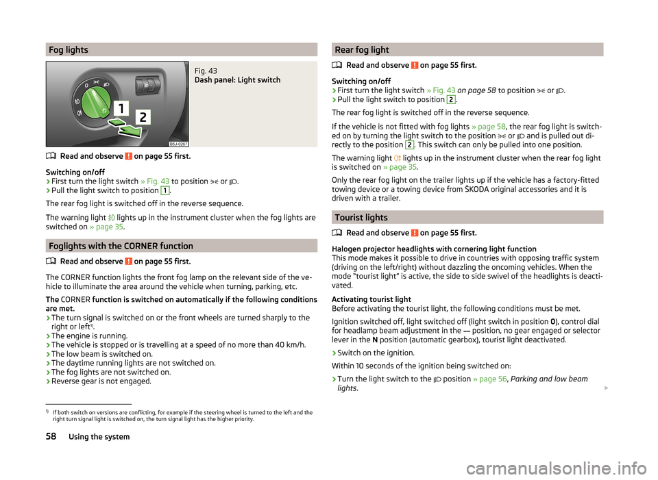
Fog lightsFig. 43
Dash panel: Light switch
Read and observe on page 55 first.
Switching on/off
›
First turn the light switch » Fig. 43 to position
or
.
›
Pull the light switch to position
1
.
The rear fog light is switched off in the reverse sequence.
The warning light lights up in the instrument cluster when the fog lights are
switched on » page 35.
Foglights with the CORNER function
Read and observe
on page 55 first.
The CORNER function lights the front fog lamp on the relevant side of the ve-
hicle to illuminate the area around the vehicle when turning, parking, etc.
The CORNER function is switched on automatically if the following conditions
are met.
› The turn signal is switched on or the front wheels are turned sharply to the
right or left 1)
.
› The engine is running.
› The vehicle is stopped or is travelling at a speed of no more than 40 km/h.
› The low beam is switched on.
› The daytime running lights are not switched on.
› The fog lights are not switched on.
› Reverse gear is not engaged.
Rear fog light
Read and observe
on page 55 first.
Switching on/off
›
First turn the light switch » Fig. 43 on page 58 to position
or
.
›
Pull the light switch to position
2
.
The rear fog light is switched off in the reverse sequence.
If the vehicle is not fitted with fog lights » page 58, the rear fog light is switch-
ed on by turning the light switch to the position
or
and is pulled out di-
rectly to the position
2
. This switch can only be pulled into one position.
The warning light lights up in the instrument cluster when the rear fog light
is switched on » page 35.
Only the rear fog light on the trailer lights up if the vehicle has a factory-fitted
towing device or a towing device from ŠKODA original accessories and it is
driven with a trailer.
Tourist lights
Read and observe
on page 55 first.
Halogen projector headlights with cornering light function
This mode makes it possible to drive in countries with opposing traffic system
(driving on the left/right) without dazzling the oncoming vehicles. When the
mode “tourist light” is active, the side to side swivel of the headlights is deacti-
vated.
Activating tourist light
Before activating the tourist light, the following conditions must be met.
Ignition switched off, light switched off (light switch in position 0), control dial
for headlamp beam adjustment in the position, no gear engaged or selector
lever in the N position (automatic gearbox), tourist light deactivated.
›
Switch on the ignition.
Within 10 seconds of the ignition being switched on:
›
Turn the light switch to the position
» page 56 , Parking and low beam
lights .
1)
If both switch on versions are conflicting, for example if the steering wheel is turned to the left and the
right turn signal light is switched on, the turn signal light has the higher priority.
58Using the system