SKODA FABIA 2014 2.G / 5J Owner's Guide
Manufacturer: SKODA, Model Year: 2014, Model line: FABIA, Model: SKODA FABIA 2014 2.G / 5JPages: 197, PDF Size: 13.56 MB
Page 21 of 197

›Check whether the 3
warning light in the mes-
sage in the centre of the dash panel does not light up after the ignition is
switched on.WARNING■ The driver is responsible for whether the airbag is switched on or switch-
ed off.■
Only switch off the airbag when the ignition is switched off! Otherwise a
fault can occur in the system for deactivating the airbag.
■
If the
warning light flashes, the front passenger airbag will not be
deployed in the event of an accident. Have the airbag system checked by a
specialist garage immediately.
■
The key cannot be inserted in the key switch while driving.
■ Shocks can cause the key to turn in the slot and trigger the airbag!
■ The airbag can be triggered unexpectedly in an accident - it may result
in injury or death!
CAUTION
An insufficiently folded out key bit can damage the key switch!Transporting children safely
Child seat
Introduction
This chapter contains information on the following subjects:
Use of a child seat on the front passenger seat
20
Child safety and side airbag
21
Classification of child seats
21
Use of child seats fastened with a seat belt
21
Children are generally safer on the rear seats than on the front passenger
seat.
In contrast to adults, the muscles and bone structure of children are not yet
fully developed. Thus children are exposed to increased risk of injury.
Children should be transported in accordance with the relevant statutory pro-
visions.
Child seats that comply with the ECE-R 44 standard must be used. The ECE-R
standard stands for: Economic Commission for Europe - Regulation.
Child seats that comply with the ECE-R 44 standard have a test seal that can-
not be removed: a large E within a circle with the test number below.
WARNING■ The national legal requirements must be observed when using child
seats.■
One should never carry children, and also not babies! - on one's lap.
■
Never leave children unattended in the vehicle. Certain outside climatic
conditions can cause life-threatening temperatures in the vehicle.
■
The child must be secured in the vehicle throughout the journey. Other-
wise, in the event of an accident, the child would be thrown through the
vehicle and as a result may suffer fatal injuries, and also injure other occu-
pants.
■
Children are exposed to an increased risk of injury in the event of an acci-
dent if they lean forward or adopt an incorrect seated position when the
vehicle is moving. This particularly applies to children who are transported
on the front passenger seat as they can suffer severe, or even fatal injuries
if the airbag system is deployed!
19Transporting children safely
Page 22 of 197

WARNING (Continued)■Pay particular attention to the information provided by the manufacturer
of the child safety seat regarding the correct routing of the belt. Seat belts
which are not correctly adjusted can themselves cause injuries even in mi-
nor accidents.■
Safety belts must be checked to ensure that they are running properly.
One should also ensure that the belt is not damaged by sharp-edged fit-
tings.
■
It is essential to switch off the front passenger airbag if using a child seat
on the front passenger seat in which the child is carried with its back facing
the direction of travel. Further information » page 20, Use of a child seat
on the front passenger seat .
Note
We recommend that you use child seats from ŠKODA Original Accessories.
These child seats were developed and also tested for use in ŠKODA vehicles.
They meet the ECE-R 44 standard.
Use of a child seat on the front passenger seat
Never use a rearward-facing child restraint system on a seat which is protec-
ted by an active airbag installed in front of it. This could cause serious injury to
the child, even death.
Fig. 13
Sticker on the B column on the
front passenger side.
Fig. 14
Front passenger sun visor / label
Read and observe
on page 19 first.
For safety reasons, we recommend that you install child seats on the rear
seats whenever possible.
The following advice must be heeded when using a child seat in which the
child is carried on the front passenger seat.
› It is essential to switch off the front passenger airbag if using a child seat in
which the child is carried with its back facing the direction of travel »
.
› Adjust the front passenger seat back as vertically as possible so that there is
firm contact passenger seat back and the child seat back.
› Where possible, move the front passenger seat back so that there is no con-
tact between the front seat and the child seat behind.
› In the case of Group 2 or 3 child seats, make sure that the deflector pulley
mounted on the child seat headrest is in front of or level with the pulley on
the B-pillar on the passenger side.
› Set the height-adjustable front passenger seat as high up as possible.
› Set the front passenger seat belt as high up as possible.
› Place and fasten the child seat on the seat and the child in the child seat ac-
cording to the specifications in the manufacturer's user manual of the child
seat .
20Safety
Page 23 of 197

WARNING■It is essential to switch off the front passenger airbag if you are using a
child seat on the front passenger seat in which the child is carried with its
back facing the direction of travel » page 17, Deactivating airbags .■
Never use a child safety seat on the front passenger seat in which the
child is seated with its back facing the direction of travel if the airbag is
switched on. This child safety seat is positioned in the deployment area of
the front passenger airbag. The airbag may cause the child severe, or even
fatal injuries, in the event of it being deployed.
■
This fact is also indicated by the label that can be found in one of the fol-
lowing locations. ■ On the B-column on the front passenger side » Fig. 13. The sticker is
visible when opening the front passenger door. ■ On the front passenger's sun visor. In some countries, the sticker is lo-
cated on the front seat passenger's sun visor » Fig. 14.
■
In the case of Group 2 or 3 child seats, make sure that the deflector pulley
mounted on the child seat headrest is in front of or level with the pulley on
the B-pillar on the passenger side.
■
The front passenger airbag should be switched on again once the child
seat, in which the child is transported with the back to the direction of trav-
el, is no longer in use on the passenger seat.
Child safety and side airbag
Fig. 15
Incorrect seated position of a
child who is not properly secured
– risk from the side airbag/Child
properly protected by safety seat
Read and observe on page 19 first.
The child must not be positioned in the area into which the side airbag will de- ploy » Fig. 15 -
.
There must be sufficient room between the child and the area into which the
side airbag will deploy to allow the airbag to provide as much protection as
possible » Fig. 15 -
.
WARNING■
Children must never be seated with their head in the deployment area of
the side airbag – there is a risk of injury.■
Do not place any objects within the deployment area of the side airbags –
there is a risk of injury.
Classification of child seats
Read and observe
on page 19 first.
Classification of child seats according to the ECE-R 44 standard.
GroupWeight of the childApproximate age0up to 10 kgup to 9 months0+up to 13 kgup to 18 months19-18 kgup to 4 years215-25 kgup to 7 years322-36 kgover 7 years
Use of child seats fastened with a seat belt Read and observe
on page 19 first.
Overview of the use of child seats fastened with a seat belt on each of the
seats in accordance with the ECE-R 16 standard.
GroupFront passenger seatRear seatsouterRear seatCenter0
up to 10 kgUUU0+
up to 13 kgUUU1
9-18 kgUUU2
15-25 kgUUU3
22-36 kgUUU 21Transporting children safely
Page 24 of 197
“Universal” child seat category - a child seat designed for fastening on
the seat with the seat belt.
Fastening systems
Introduction
This chapter contains information on the following subjects:
ISOFIX system attachment points
22
Use of child seats with the ISOFIX system
22
TOP TETHER system attachment points
23
ISOFIX system attachment points
Fig. 16
ISOFIX system label
UThere are two locking eyes between the rear exterior seats for fixing the
ISOFIX system child seat in place.
The places are marked with labels with the ISOFIX logo » Fig. 16.WARNING■
Always refer to the instructions from the manufacturer of the child seat
when installing and removing a child seat with the ISOFIX system.■
Never attach other child seats, belts or objects to the attachment points
eyes intended for the installation of a child seat with the ISOFIX system –
risk of death.
Note
■ A child seat fitted with the ISOFIX system can only be mounted in a vehicle
fitted with an ISOFIX system if the child seat has been approved for this type
of vehicle. Further information is available from a ŠKODA Partner.■
Child seats with the ISOFIX system can be purchased from ŠKODA Original
Accessories.
Use of child seats with the ISOFIX system
Overview of the use of child seats fastened with the ISOFIX system on each of
the seats in accordance with the ECE-R 16 standard.GroupSize class
of the child seat a)Front passenger seat
b)Outer rear seatsRear seat middle0
up to 10 kgEXIL-SUX0+
up to 13 kgE
XIL-SUX
DC 22Safety
Page 25 of 197
GroupSize class
of the child seat a)Front passenger seat
b)Outer rear seatsRear seat middle
1
9-18 kg
D
XIL-SU IUFX
CBB1Aa)
The size category is shown on the label attached to the child seat.
b)
If the front passenger seat is fitted with the ISOFIX system attachment points, it is suited for the installation of an ISOFIX child seat with the “Semi-Universal” approval.
The seat is suited for installation of an ISOFIX child seat with the “Semi-
Universal” approval. The “Semi-Universal” category means that the ISO-
FIX child seat is approved for your vehicle. Observe the information in
the list of vehicles which comes with the child seat.
The seat is suitable for the installation of an ISOFIX child seat with the approval “Universal” and attachment with the TOP TETHER belt.
The seat is not fitted with ISOFIX system attachment points.
TOP TETHER system attachment points
Fig. 17
Anchor eyelets on the TOP
TETHER system
The anchor eyelets for attaching the belt for a child seat with the TOP TETHER
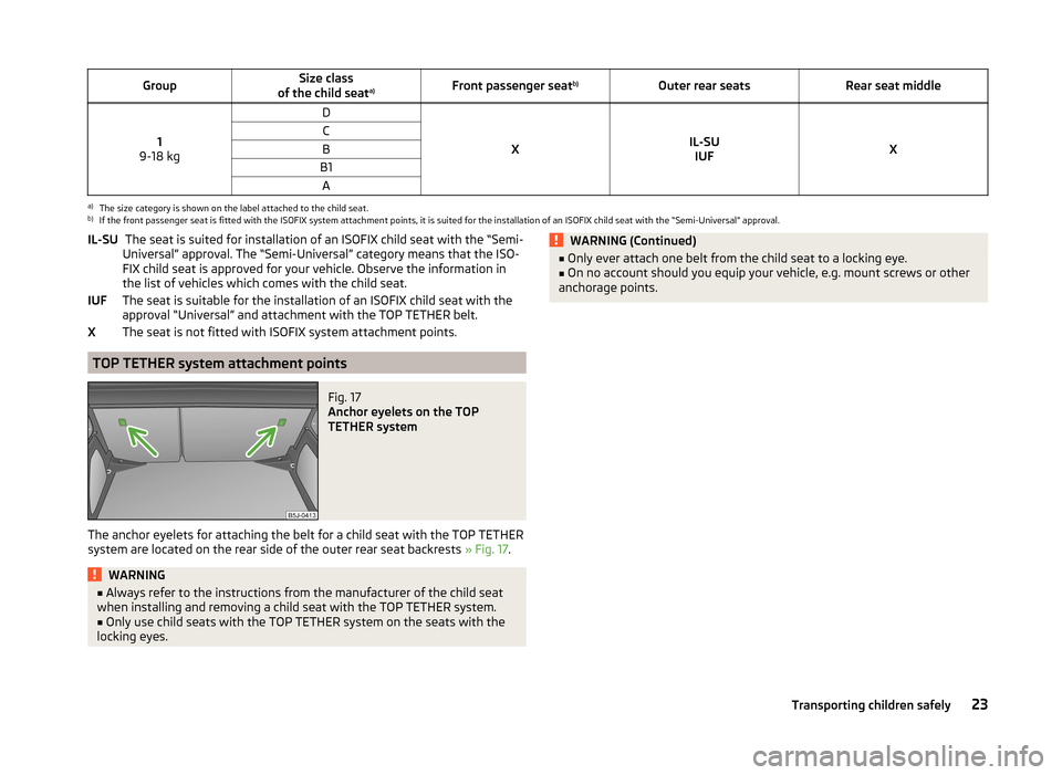
system are located on the rear side of the outer rear seat backrests » Fig. 17.
WARNING■
Always refer to the instructions from the manufacturer of the child seat
when installing and removing a child seat with the TOP TETHER system.■
Only use child seats with the TOP TETHER system on the seats with the
locking eyes.
IL-SUIUFXWARNING (Continued)■ Only ever attach one belt from the child seat to a locking eye.■On no account should you equip your vehicle, e.g. mount screws or other
anchorage points.23Transporting children safely
Page 26 of 197

Fig. 18
Cockpit
24Using the system
Page 27 of 197
Using the system
Cockpit
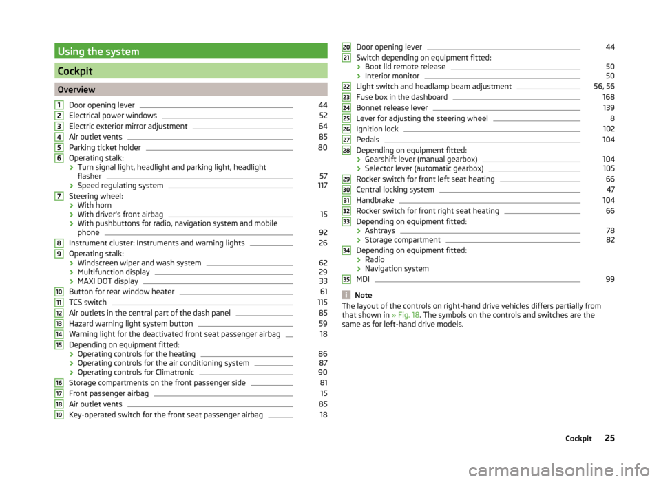
OverviewDoor opening lever
44
Electrical power windows
52
Electric exterior mirror adjustment
64
Air outlet vents
85
Parking ticket holder
80
Operating stalk:
› Turn signal light, headlight and parking light, headlight
flasher
57
› Speed regulating system
117
Steering wheel:
› With horn
› With driver’s front airbag
15
›With pushbuttons for radio, navigation system and mobile
phone
92
Instrument cluster: Instruments and warning lights
26
Operating stalk:
› Windscreen wiper and wash system
62
›Multifunction display
29
›MAXI DOT display
33
Button for rear window heater
61
TCS switch
115
Air outlets in the central part of the dash panel
85
Hazard warning light system button
59
Warning light for the deactivated front seat passenger airbag
18
Depending on equipment fitted:
› Operating controls for the heating
86
›Operating controls for the air conditioning system
87
›Operating controls for Climatronic
90
Storage compartments on the front passenger side
81
Front passenger airbag
15
Air outlet vents
85
Key-operated switch for the front seat passenger airbag
1812345678910111213141516171819Door opening lever44
Switch depending on equipment fitted:
› Boot lid remote release
50
›Interior monitor
50
Light switch and headlamp beam adjustment
56, 56
Fuse box in the dashboard
168
Bonnet release lever
139
Lever for adjusting the steering wheel
8
Ignition lock
102
Pedals
104
Depending on equipment fitted:
› Gearshift lever (manual gearbox)
104
›Selector lever (automatic gearbox)
105
Rocker switch for front left seat heating
66
Central locking system
47
Handbrake
104
Rocker switch for front right seat heating
66
Depending on equipment fitted:
› Ashtrays
78
›Storage compartment
82
Depending on equipment fitted:
› Radio
› Navigation system
MDI
99
Note
The layout of the controls on right-hand drive vehicles differs partially from
that shown in » Fig. 18. The symbols on the controls and switches are the
same as for left-hand drive models.2021222324252627282930313233343525Cockpit
Page 28 of 197
Instruments and Indicator Lights
Instrument cluster
Introduction
This chapter contains information on the following subjects:
Overview
26
Engine revolutions counter
27
Speedometer
27
Coolant temperature gauge display
27
Fuel gauge
27
Counter for distance driven
28
Digital clock
28
Display of the second speed
28
Recommended gear
28
Fault display
The Error message will appear in the display if there is a fault in the instru-
ment cluster. Ensure that the fault is rectified as soon as possible by a special-
ist workshop.
WARNING■ Concentrate fully at all times on your driving! As the driver you are fully
responsible for road safety.■
Never operate the controls in the instrument cluster while driving, only
when the vehicle is stationary!
OverviewFig. 19
Instrument cluster
Read and observe
on page 26 first.
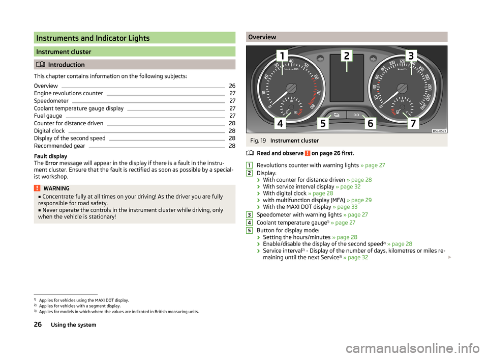
Revolutions counter with warning lights » page 27
Display:
› With counter for distance driven
» page 28
› With service interval display
» page 32
› With digital clock
» page 28
› with multifunction display (MFA)
» page 29
› With the MAXI DOT display
» page 33
Speedometer with warning lights » page 27
Coolant temperature gauge 1)
» page 27
Button for display mode:
› Setting the hours/minutes
» page 28
› Enable/disable the display of the second speed 2)
» page 28
› Service interval 2)
- Display of the number of days, kilometres or miles re-
maining until the next Service 3)
» page 32
123451)
Applies for vehicles using the MAXI DOT display.
2)
Applies for vehicles with a segment display.
3)
Applies for models in which where the values are indicated in British measuring units.
26Using the system
Page 29 of 197
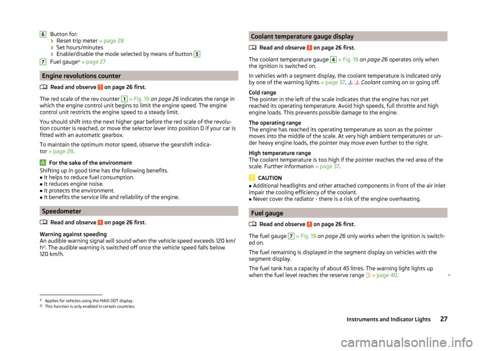
Button for:› Reset trip meter
» page 28
› Set hours/minutes
› Enable/disable the mode selected by means of button 5
Fuel gauge 1)
» page 27
Engine revolutions counter
Read and observe
on page 26 first.
The red scale of the rev counter
1
» Fig. 19 on page 26 indicates the range in
which the engine control unit begins to limit the engine speed. The engine
control unit restricts the engine speed to a steady limit.
You should shift into the next higher gear before the red scale of the revolu- tion counter is reached, or move the selector lever into position D if your car is
fitted with an automatic gearbox.
To maintain the optimum motor speed, observe the gearshift indica-
tor » page 28 .
For the sake of the environment
Shifting up in good time has the following benefits.■It helps to reduce fuel consumption.■
It reduces engine noise.
■
It protects the environment.
■
It benefits the service life and reliability of the engine.
Speedometer
Read and observe
on page 26 first.
Warning against speeding
An audible warning signal will sound when the vehicle speed exceeds 120 km/
h 2)
. The audible warning is switched off once the vehicle speed falls below
120 km/h.
67Coolant temperature gauge display
Read and observe
on page 26 first.
The coolant temperature gauge
4
» Fig. 19 on page 26 operates only when
the ignition is switched on.
In vehicles with a segment display, the coolant temperature is indicated only
by one of the warning lights » page 37,
Coolant coming on or going off.
Cold range
The pointer in the left of the scale indicates that the engine has not yet
reached its operating temperature. Avoid high speeds, full throttle and high engine loads. This prevents possible damage to the engine.
The operating range
The engine has reached its operating temperature as soon as the pointer
moves into the middle of the scale. At very high ambient temperatures or un-
der heavy engine loads, the pointer may move even further to the right.
High temperature range
The coolant temperature is too high if the pointer reaches the red area of the
scale. Further information » page 37.
CAUTION
■
Additional headlights and other attached components in front of the air inlet
impair the cooling efficiency of the coolant.■
Never cover the radiator - there is a risk of the engine overheating.
Fuel gauge
Read and observe
on page 26 first.
The fuel gauge
7
» Fig. 19 on page 26 only works when the ignition is switch-
ed on.
The fuel remaining is displayed in the segment display on vehicles with the
segment display.
The fuel tank has a capacity of about 45 litres. The warning light lights up
when the fuel level reaches the reserve range
» page 40 .
1)
Applies for vehicles using the MAXI DOT display.
2)
This function is only enabled in certain countries.
27Instruments and Indicator Lights
Page 30 of 197
CAUTIONNever drive until the fuel tank is completely empty! The irregular supply of fuel
can cause misfiring. This can result in considerable damage to parts of the en-
gine and the exhaust system.
Counter for distance driven
Read and observe
on page 26 first.
The distance which you have driven with your vehicle is shown in km. In some
countries the measuring unit “mile” is used.
Daily trip counter (trip)
The trip counter indicates the distance you have driven since it was last reset -
in steps of 100 metres or 1/10 of a mile.
Reset trip meter
The meter can be reset by pressing and holding button
6
» Fig. 19 on page 26 .
Odometer
The odometer indicates the total distance in kilometres or miles which the ve-
hicle has been driven.
Note
If the second speed display is enabled on vehicles with a segment display, this
speed will be shown instead of the odometer.
Digital clock
Read and observe
on page 26 first.
The clock is set with buttons
5
and
6
» Fig. 19 on page 26 .
Select the display that you wish to change with the button
5
and carry out
the change with the button
6
.
In vehicles equipped with the MAXI DOT display, it is also possible to set the
clock in the Time menu » page 34.
Display of the second speed
Read and observe
on page 26 first.
The display can show the current speed in mph 1)
.
This feature is provided for driving in countries with different units for speed.
MAXI DOT display
The display of the second speed can be set in the Settings menu
item » page 34 , Settings .
Segment display
›
Press the
5
» Fig. 19 on page 26 key repeatedly, until the odometer display
flashes » page 28 .
›
Press the
6
key while the display is flashing.
The second speed is displayed instead of the odometer.
Display of the second speed can be disabled in the same way.
Recommended gear
Fig. 20
Recommended gear
Read and observe on page 26 first.
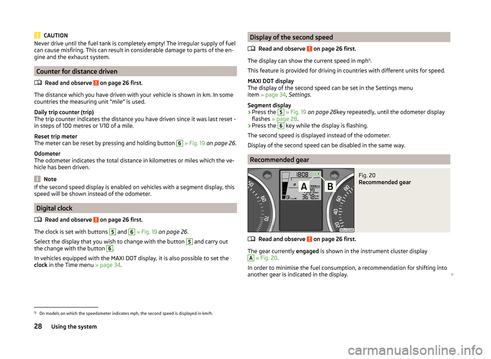
The gear currently engaged is shown in the instrument cluster display
A
» Fig. 20 .
In order to minimise the fuel consumption, a recommendation for shifting into
another gear is indicated in the display.
1)
On models on which the speedometer indicates mph, the second speed is displayed in km/h.
28Using the system