engine SKODA SUPERB 2016 3.G / (B8/3V) Owner's Guide
[x] Cancel search | Manufacturer: SKODA, Model Year: 2016, Model line: SUPERB, Model: SKODA SUPERB 2016 3.G / (B8/3V)Pages: 336, PDF Size: 53.89 MB
Page 87 of 336
Seat heating and ventilation
Introduction
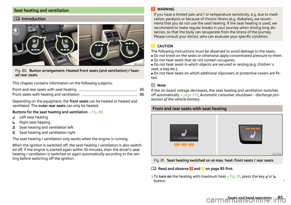
Fig. 80
Button arrangement: Heated front seats (and ventilation) / heat-
ed rear seats
This chapter contains information on the following subjects:
Front and rear seats with seat heating
85
Front seats with heating and ventilation
86
Depending on the equipment, the front seats can be heated or heated and
ventilated. The outer rear seats can only be heated.
Buttons for the seat heating and ventilation » Fig. 80
Left seat heating
Right seat heating
Seat heating and ventilation left
Seat heating and ventilation right
The seat heating / ventilation only works when the engine is running. When the ignition is switched off, the seat heating / ventilation is also switch-ed off. if the engine is started again within 10 minutes, then the driver's seat
heating / ventilation is switched on again automatically according to the set-
ting before switching off the ignition.
WARNINGIf you have a limited pain and / or temperature sensitivity, e.g. due to medi-
cation, paralysis or because of chronic illness (e.g. diabetes), we recom-
mend that you do not use the seat heating. If the seat heating is used, we
recommend to make regular breaks in your journey when driving long dis-
tances, so that the body can recuperate from the stress of the journey.
Please consult your doctor, who can evaluate your specific condition.
CAUTION
The following instructions must be observed to avoid damage to the seats.■Do not kneel on the seats or otherwise apply concentrated pressure to them.■
Do not heat seats that do not contain occupants.
■
Do not heat seats in which objects are secured or resting (e.g. children´s
seat, a bag etc.).
■
Do not heat seats on which additional slipcovers or protective covers are fit-
ted.
Note
If the on-board voltage decreases, the seat heating and ventilation switches
off automatically » page 273, Automatic consumer shutdown - discharge pro-
tection of the vehicle battery .
Front and rear seats with seat heating
Fig. 81
Seat heating switched on at max. heat: front seats / rear seats
Read and observe
and on page 85 first.
›
To turn on the heating with maximum heat » Fig. 81, press the key
or
button.
85Seats and head restraints
Page 89 of 336

Heated steering wheel, along with the driver's seat heating›To activate / deactivate the heated steering wheel with the driver's seat
heating, press the button
on the Climatronic, then tap on the function
surface
→
Link seats and steering wheel heating
in the Infotainment screen.
›
To switch on / off the heated steering wheel, press the button for the driver
seat heating.
Setting the heat output of the steering wheel heater
›
Press the button
on the Climatronic, then tap the function surface
→
intensity
on the Infotainment screen.
›
Select one of the three heating levels (this remains stored even after switch-
ing off the engine).
The selected heat output of the heated steering wheel is shown on the Info- tainment screen
B
» Fig. 84 ,
Note
■
The heated steering wheel only works when the engine is running.■If the on-board voltage decreases, the heated steering wheel switches off
automatically.Practical features
Interior equipment
Introduction
This chapter contains information on the following subjects:
Parking ticket holder
88
Storage compartment on the driver's side
88
stowage compartments in the doors
88
Storage compartment in the front centre console
89
Phonebox
89
USB and AUX inputs
90
Cup holders
90
Waste container
91
Storage compartment under the front arm rest
91
Glasses compartment
92
Storage compartment on the front passenger side
92
Storage compartment under the front passenger seat
93
Storage compartments for umbrella
93
Clothes hook
93
Storage pockets on the backs of the front seats
94
Storage pockets at the inner sides of the front seats
94
Storage compartment in the rear centre console
94
Storage compartment in the rear armrest
94
Long cargo channel
95
Removable through-loading bag
95WARNING■ Do not place anything on the dashboard. These objects might slide or fall
down when driving and may distract you from concentrating on the traffic –
risk of accident!■
Make sure that while driving no objects can enter the driver's footwell -
cause an accident!
■
Do not carry any objects on the front passenger seat except objects de-
signed for this purpose (e.g. child seats) – risk of accident!
87Practical features
Page 98 of 336

CAUTIONNever fold and stow the through-loading bag when it is wet - risk of damaging
the through-loading bag.
Electrical sockets
Introduction
This chapter contains information on the following subjects:
12-volt socket in the front centre console
96
12 volt socket in the rear centre console
96
12 volt socket in luggage compartment
97
230-volt socket in the rear centre console
97WARNING■ Do not place anything on the dashboard. These objects might slide or fall
down when driving and may distract you from concentrating on the traffic –
risk of accident!■
Make sure that while driving no objects can enter the driver's footwell -
cause an accident!
■
Safely stow all devices during the journey to prevent them from being
thrown around the interior in the event of a sudden braking manoeuvre or
an accident – risk of death!
■
The devices may warm up during operation – risk of injury or fire!
■
Improper use of the power sockets and the electrical accessories can
cause fires, burns and other serious injuries.
■
The 12-Volt sockets also work if the ignition is switched off. When leaving
the vehicle, never leave persons who are not completely independent, such
as children, unattended in the vehicle.
CAUTION
When using the 12 volt power outlets the following notes are to be observed.■The sockets can only be used for the connection of approved electrical ac-
cessories with a total power consumption of up to 120 watts, otherwise the
electrical system of the vehicle may be damaged.■
Connecting appliances when the engine is not running will drain the battery
of the vehicle!
■
Before switching the ignition on / off or before starting the engine, switch
off the devices which are connected to the sockets - there is a risk of damage
to the equipment due to voltage fluctuations.
12-volt socket in the front centre consoleFig. 108
Cover of the 12 volt power outlet
Read and observe and on page 96 first.
›
To use , open the storage compartment, remove the cover of the socket
» Fig. 108 and plug the electrical appliance plug into the socket.
12 volt socket in the rear centre console
Fig. 109
Open the cover / 12 volt power outlet
96Using the system
Page 99 of 336
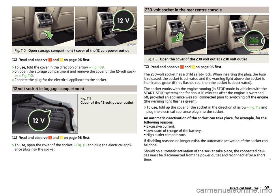
Fig. 110
Open storage compartment / cover of the 12 volt power outlet
Read and observe
and on page 96 first.
›
To use , fold the cover in the direction of arrow » Fig. 109.
›
or: open the storage compartment and remove the cover of the 12-volt sock-
et » Fig. 110 .
›
Connect the plug for the electrical appliance to the socket.
12 volt socket in luggage compartment
Fig. 111
Cover of the 12 volt power outlet
Read and observe and on page 96 first.
›
To use , open the cover of the socket » Fig. 111 and plug the electrical appli-
ance plug into the socket.
230-volt socket in the rear centre consoleFig. 112
Open the cover of the 230 volt outlet / 230 volt outlet
Read and observe
and on page 96 first.
The 230-volt socket has a child safety lock. When inserting the plug, the fuse
is released, the socket is activated and the warning light above the socket is
illuminates green (if this flashes red, then the socket is deactivated).
The socket works with the engine running (in STOP mode in vehicles with the
START-STOP system) and for about 10 minutes after the engine is switched
off, provided an appliance was still connected prior to switching off the engine
(the warning light flashes green)).
›
To use , fold up the cover of the socket in the direction of arrow » Fig. 112 and
plug the electrical appliance plug into the socket.
An automatic deactivation of the socket can take place, for example, for the
following reasons. ▶ Excessive current.
▶ Low state of charge of the battery.
▶ High outlet temperature.
If disabling reasons no longer exist, the automatic activation of the socket can
be done.
Should no automatic activation of the socket take place, the connected devi-
ces must be disconnected from the power outlet and reconnect after a short
time.
97Practical features
Page 111 of 336
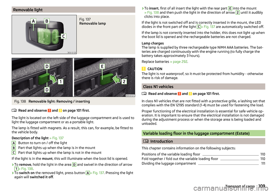
Removable lightFig. 137
Removable lamp
Fig. 138
Removable light: Removing / inserting
Read and observe
and on page 101 first.
The light is located on the left side of the luggage compartment and is used to light the luggage compartment or as a portable light.
The lamp is fitted with magnets. As a result, this can, for example, be fitted to
the vehicle body.
Description of the light » Fig. 137
Button to turn on / off the light
Part that lights up when the lamp is in the mount
Part that lights up when the lamp is not in the mount
If the light is in the mount, this will illuminate when the boot lid is opened.
›
To remove , hold the light in the area
D
and swivel in the direction of arrow
1
» Fig. 138 .
›
To switch on the removed light, press button
A
» Fig. 137. Pressing the light
again will switched it off .
ABC›To
insert , first of all insert the light with the rear part E into the mount
» Fig. 138 and then push the light in the direction of arrow 2 until it audibly
clicks into place.
If the light is not switched off and is correctly inserted in the mount, the LED diodes in the front part of the light C
» Fig. 137 are automatically switched off.
If the lamp is not correctly inserted into the holder, this does not light up when
the boot lid is opened and the rechargeable batteries are not charged.
Lamp charges
The lamp is supplied by three rechargeable type NiMH AAA batteries. The bat-
teries are charged continuously with the engine running (to fully charge the
battery takes approximately 3 hours).
Replace batteries » page 292.
CAUTION
The light is not waterproof, so it must be protected from humidity - otherwise
there is risk of damage.
Class N1 vehicles
Read and observe
and on page 101 first.
In class N1 vehicles that are not fitted with a protective grille, a lashing set that
complies with the EN 12195 standard (1-4) must be used for fastening the load.
Proper functioning of the electrical installation is essential for safe vehicle op-
eration. It is important to ensure that the electrical installation is not damaged
during the adjustment process or when the storage area is being loaded and
unloaded.
Variable loading floor in the luggage compartment (Estate)
Introduction
This chapter contains information on the following subjects:
Positions of the variable loading floor
110
Fold together / fold out the variable loading floor
110
Dividing the luggage compartment
111109Transport of cargo
Page 115 of 336
NoteWe recommend that you use a roof rack from ŠKODA Original Accessories.Heating and ventilation
Heating, manual air conditioning system, Climatronic
Introduction
This chapter contains information on the following subjects:
Heating and manual air conditioning
114
Climatronic (automatic air conditioning)
114
Operate Climatronic in Infotainment
116
Climatronic - automatic operation
116
Air distribution control
117
Air outlet vents
117
The heating heats and ventilates the vehicle interior. The air conditioning sys-
tem also cools and dehumidifies the vehicle interior.
The heating effect is dependent upon the coolant temperature, thus full heat
output only occurs when the engine has reached its operating temperature.
The cooling system works under the following conditions. The cooling system is switched on.
The engine is running.
The outside temperature is below 2 ° C.
The blower is switched on.
Fogging is prevented when the cooling system is switched on.
It is possible to boost the effectiveness of the cooling system by briefly acti-
vating the air recirculation system » page 117.
Health protection
To reduce health risks (e.g. common colds), the following instructions for the
use of the cooling system are to be observed. ▶ The difference between the indoor temperature and the outdoor air temper-
ature should not be greater than about 5 ° C.
▶ The cooling system should be turned off about 10 minutes before the end of
the journey.
▶ Once a year, the air conditioning should be disinfected by a specialist garage.
113Heating and ventilation
Page 116 of 336
WARNING■The blower should always be on to prevent the windows from misting.
Otherwise there could be an accident.■
Under certain circumstances, air at a temperature of about 5 °C can flow
out of the vents when the cooling system is switched on.
Note
■ The air inlet in front of the windscreen must be free of e.g. ice, snow or
leaves to ensure that the heating and cooling system operates properly.■
After switching on the cooling Condensation from the evaporator of the air
conditioning may drip down and form a puddle below the vehicle. This is not a
leak!
■
If the coolant temperature is too high, the cooling system is switched off to
ensure that the engine cools down.
Heating and manual air conditioning
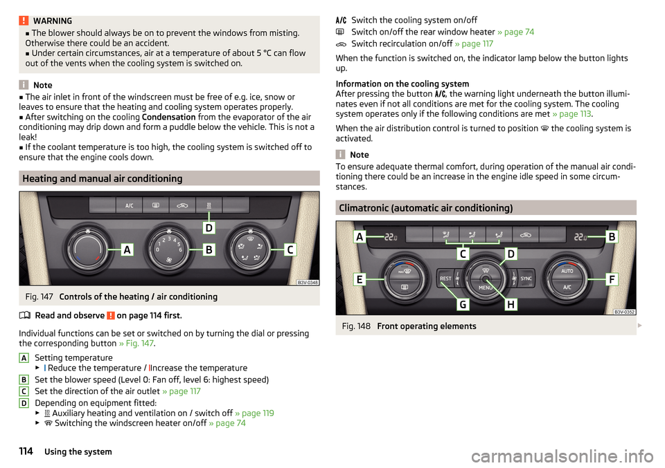
Fig. 147
Controls of the heating / air conditioning
Read and observe
on page 114 first.
Individual functions can be set or switched on by turning the dial or pressing the corresponding button » Fig. 147.
Setting temperature
▶ Reduce the temperature /
Increase the temperature
Set the blower speed (Level 0: Fan off, level 6: highest speed)
Set the direction of the air outlet » page 117
Depending on equipment fitted:
▶ Auxiliary heating and ventilation on / switch off
» page 119
▶ Switching the windscreen heater on/off
» page 74
ABCDSwitch the cooling system on/off
Switch on/off the rear window heater » page 74
Switch recirculation on/off » page 117
When the function is switched on, the indicator lamp below the button lights up.
Information on the cooling system
After pressing the button
, the warning light underneath the button illumi-
nates even if not all conditions are met for the cooling system. The cooling
system operates only if the following conditions are met » page 113.
When the air distribution control is turned to position
the cooling system is
activated.
Note
To ensure adequate thermal comfort, during operation of the manual air condi-
tioning there could be an increase in the engine idle speed in some circum-
stances.
Climatronic (automatic air conditioning)
Fig. 148
Front operating elements
114Using the system
Page 117 of 336
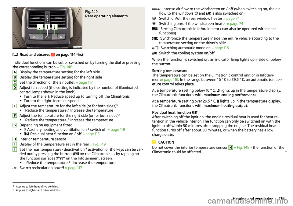
Fig. 149
Rear operating elements
Read and observe on page 114 first.
Individual functions can be set or switched on by turning the dial or pressingthe corresponding button » Fig. 148.
Display the temperature setting for the left side
Display the temperature setting for the right side
Set the direction of the air outlet » page 117
Adjust fan speed (the setting is indicated by the number of illuminated
control lamps shown in the knob)
▶ Turn to the left: Reduce speed up to turning off the Climatronic
▶ Turn to the right: Increase speed
Adjust the temperature for the left side (or for both sides) 1)
▶ Reduce the temperature /
Increase the temperature
Adjust the temperature for the right side (or for both sides) 2)
▶ Reduce the temperature /
Increase the temperature
Depending on equipment fitted:
▶ Auxiliary heating and ventilation on / switch off
» page 119
▶ Residual heat function on / off
» page 115
Interior temperature sensor
Display of the temperature set in the rear » Fig. 149
Set the rear temperature- deactivation / activation of the keys can be car-
ried out by pressing the button on the Climatronic
→ by tapping on
the function surfaces on the Infotainment screen.
▶ Reduce the temperature /
Increase the temperature
Switch recirculation on/off » page 117
ABCDEFGHIJIntense air flow to the windscreen on / off (when switching on, the air
flow to the windows and is also switched on)
Switch on/off the rear window heater » page 74
Switching on/off the windscreen heater » page 74
Setting Climatronic in Infotainment ( can also be operated with some
functions)
Synchronize the temperature inside the entire vehicle according to the
temperature setting on the driver's side
Switching automatic mode on » page 116
Switch the cooling system on/off
When the function is switched on, an indicator lamp lights up inside or below
the button.
Setting temperature
The temperature can be set on the Climatronic control unit or in Infotain-
ment » page 116 . In the range between 16 ° C to 29.5 ° C, an automatic temper-
ature control takes place.
At a temperature setting below 16 ° C, lights up in the temperature display,
the Climatronic functions with maximum cooling performance .
At a temperature setting over 29.5 ° C, lights up in the temperature display,
the Climatronic functions with maximum heating output.
Residual heat function
After switching off the ignition, the engine residual heat is used for heat re-
tention in the vehicle interior. The function can only be switched on with the
ignition off within 30 minutes after stopping the engine. The residual heat
function turns off after about 30 minutes, or when the battery has a low
charge state.
CAUTION
Do not cover the interior temperature sensor H » Fig. 148 - the function of the
Climatronic could be affected. 1)
Applies to left-hand drive vehicles.
2)
Applies to right-hand drive vehicles.
115Heating and ventilation
Page 120 of 336
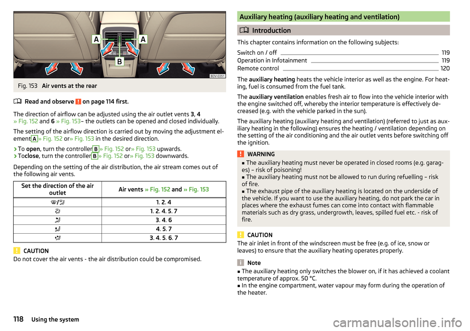
Fig. 153
Air vents at the rear
Read and observe
on page 114 first.
The direction of airflow can be adjusted using the air outlet vents 3, 4
» Fig. 152 and 6 » Fig. 153 – the outlets can be opened and closed individually.
The setting of the airflow direction is carried out by moving the adjustment el-
ement
A
» Fig. 152 or» Fig. 153 in the desired direction.
›
To open , turn the controller
B
» Fig. 152 or» Fig. 153 upwards.
›
Toclose , turn the controller
B
» Fig. 152 or» Fig. 153 downwards.
Depending on the setting of the air distribution, the air stream comes out of
the following air vents.
Set the direction of the air outletAir vents » Fig. 152 and » Fig. 1531. 2 . 41. 2 . 4 . 5 . 73 . 4 . 64 . 5 . 73 . 4 . 5 . 6 . 7
CAUTION
Do not cover the air vents - the air distribution could be compromised.Auxiliary heating (auxiliary heating and ventilation)
Introduction
This chapter contains information on the following subjects:
Switch on / off
119
Operation in Infotainment
119
Remote control
120
The auxiliary heating heats the vehicle interior as well as the engine. For heat-
ing, fuel is consumed from the fuel tank.
The auxiliary ventilation enables fresh air to flow into the vehicle interior with
the engine switched off, whereby the interior temperature is effectively de-
creased (e.g. with the vehicle parked in the sun).
The auxiliary heating (auxiliary heating and ventilation) (referred to just as aux- iliary heating in the following) ensures the heating / ventilation depending on
the setting of the air conditioning and the air outlet vents before switching off
the ignition.
WARNING■ The auxiliary heating must never be operated in closed rooms (e.g. garag-
es) – risk of poisoning!■
The auxiliary heating must not be allowed to run during refuelling – risk
of fire.
■
The exhaust pipe of the auxiliary heating is located on the underside of
the vehicle. If you want to use the auxiliary heating, do not park the car in
places where the exhaust fumes can come into contact with flammable
materials such as dry grass, undergrowth, leaves, spilled fuel etc. - risk of
fire.
CAUTION
The air inlet in front of the windscreen must be free (e.g. of ice, snow or
leaves) to ensure that the auxiliary heating operates properly.
Note
■ The auxiliary heating only switches the blower on, if it has achieved a coolant
temperature of approx. 50 °C.■
In the engine compartment, water vapour may form during the operation of
the heater.
118Using the system
Page 128 of 336
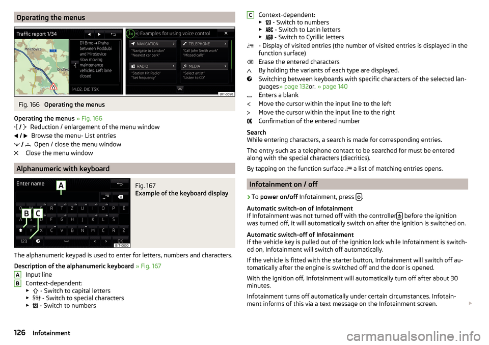
Operating the menusFig. 166
Operating the menus
Operating the menus » Fig. 166
Reduction / enlargement of the menu window Browse the menu- List entries Open / close the menu window
Close the menu window
Alphanumeric with keyboard
Fig. 167
Example of the keyboard display
The alphanumeric keypad is used to enter for letters, numbers and characters.
Description of the alphanumeric keyboard » Fig. 167
Input line
Context-dependent: ▶ - Switch to capital letters
▶ - Switch to special characters
▶ - Switch to numbers
ABContext-dependent:
▶ - Switch to numbers
▶ - Switch to Latin letters
▶
- Switch to Cyrillic letters
- Display of visited entries (the number of visited entries is displayed in the
function surface)
Erase the entered characters
By holding the variants of each type are displayed.
Switching between keyboards with specific characters of the selected lan-
guages » page 132 or. » page 140
Enters a blank
Move the cursor within the input line to the left
Move the cursor within the input line to the right
Confirmation of the entered number
Search
While entering characters, a search is made for corresponding entries.
The entry such as a telephone contact to be searched for must be entered
along with the special characters (diacritics).
By tapping on the function surface a list of matching entries opens.
Infotainment on / off
›
To
power on/off Infotainment, press .
Automatic switch-on of Infotainment
If Infotainment was not turned off with the controller
before the ignition
was turned off, it will automatically switch on after the ignition is switched on.
Automatic switch-off of Infotainment
If the vehicle key is pulled out of the ignition lock while Infotainment is switch-
ed on, Infotainment will switch off automatically.
If the vehicle is fitted with the starter button, Infotainment will switch off au-
tomatically after the engine is switched off and the door is opened.
With the ignition off, Infotainment will automatically turn off after about 30
minutes.
Infotainment turns off automatically under certain circumstances. Infotain-
ment informs of this via a text message on the Infotainment screen.
C126Infotainment