ignition switch SSANGYONG KORANDO 1997 Service Owners Manual
[x] Cancel search | Manufacturer: SSANGYONG, Model Year: 1997, Model line: KORANDO, Model: SSANGYONG KORANDO 1997Pages: 2053, PDF Size: 88.33 MB
Page 1221 of 2053

5A-126 AUTOMATIC TRANSMISSION
SSANGYONG MY2002
Circuit Description
The solenoid 7 is a normally open ON/OFF type sole-
noid that is used to control the application of the
Torque Converter Clutch (TCC).
The Solenoid 7 (S7) ON activates the TCC and the S7
is attached to the pump body within the transmission.
Voltage is supplied directly to the solenoid through
the Transmission Control Module (TCM).
The DTC P1739 sets when the solenoid 7, Torque Con-
verter Clutch Solenoid, circuit is open or the switched
leg of the solenoid 7 is shorted to battery positive.
The solenoid 7's driver Integrated Chip (IC) status
indicates a faulty circuit.
Conditions for Setting the DTC
DTCs P1717 and P1718 are not set.
S7 is OFF.
S3 is OFF.
The solenoid 7's driver Integrated Chip (IC) status
indicates a faulty circuit. This condition must be
continuously present for 60 milliseconds.
Action Taken When the DTC Sets
The solenoid 7 is always disabled (OFF) resulting
in the TCC being unlocked always.
DIAGNOSTIC TROUBLE CODE (DTC) P1739
SOLENOID 7 CIRCUIT OPEN
Conditions for Clearing the DTC
The DTC will clear when the malfunction has not
occurred after ignition cycle.
A history DTC will clear after 40 TCM power-up
cycles with a warm transmission (>50 °C) and
without a fault.
History DTCs can be cleared by using a scan tool.
Diagnostic Aids
During the TCM's testing, solenoid 7 is turned OFF/
ON by a very small (4 millisecond) pulses. This
pulse is too short for the solenoid to react so the
transmission operation is not affected.
The solenoid feedback voltage is measured before
the (4 millisecond) pulse and again during the pulse.
If the difference is outside the acceptable limits
the relevant fault is recorede.
Typical causes would be an open circuit in the wiring
to or within the solenoid, or a short circuit to power
in the wiring to or within the solenoid.
If several faults of solenoids are present, check the
wiring or connectors that are common to the selected
solenoids, especially the earth connections.
Inspect the wiring for poor electrical connections
at the TCM and at the 10-way transmission
connector.
KAC5A030
Page 1233 of 2053

5A-138 AUTOMATIC TRANSMISSION
SSANGYONG MY2002
Circuit Description
The solenoid 3 is a normally open ON/OFF type sole-
noid that is used in conjunction with the solenoid 4 to
control the shift quality and sequencing.
The solenoid 3 switches the clutch regulator valve OFF
or ON and is attached to the valve body within the
transmission. Voltage is supplied directly to the
solenoid through the Transmission Control Module
(TCM).
The DTC P1743 sets when the Solenoid 3 (S3) circuit
is shorted to ground. The solenoid 3’s driver
Integrated Chip (IC) status indicates a faulty circuit.
Conditions for Setting the DTC
DTCs P1717 and P1718 are not set.
S3 is ON.
The solenoid 3’s driver Integrated Chip (IC) status
indicates a faulty circuit. This condition must be
continuously present for 60 milliseconds.
Action Taken When the DTC Sets
The solenoid 3 is always OFF.
The 1 → 3, 1 → 4, 2 → 3, 2 → 4, 3 → 1, 3 → 2, 4 →
2 and 4 1 shift quality is degraded.
Conditions for Clearing the DTC
The DTC will clear when the malfunction has not
occurred after ignition cycle.
DIAGNOSTIC TROUBLE CODE (DTC) P1743
SOLENOID 3 CIRCUIT SHORT
A history DTC will clear after 40 TCM power-up
cycles with a warm transmission (>50 °C) and
without a fault.
History DTCs can be cleared by using a scan tool.
Diagnostic Aids
During the TCM’s testing, solenoid 3 is turned OFF/
ON by a very small (4 millisecond) pulses. This
pulse is too short for the solenoid to react so the
transmission operation is not affected.
The solenoid feedback voltage is measured before
the (4 millisecond) pulse and again during the
pulse. If the difference is outside the acceptable
limits the relevant fault is recorded.
Typical causes would be a short circuit to ground
in the wiring to or within the solenoid.
If several faults of solenoids are present, check
the wiring or connectors that are common to the
selected solenoids, especially the earth
connections.
Inspect the wiring for poor electrical connections
at the TCM and at the 10-way transmission
connector. Look for possible bent, backed out,
deformed or damaged terminals. Check for weak
terminal tension as well. Also check for chafed wires
that could short to bare metal or other wiring.
Inspect for broken wire inside the insulation.
KAC5A030
Page 1237 of 2053

5A-142 AUTOMATIC TRANSMISSION
SSANGYONG MY2002
Circuit Description
The solenoid 4 is a normally open ON/OFF type sole-
noid that is used in conjunction with the solenoid 3 to
control the shift quality and sequencing.
The solenoid 4 switches the band regulator valve OFF
or ON and is attached to the valve body within the
transmission.
Voltage is supplied directly to the solenoid through
the Transmission Control Module (TCM).
The DTC P1744 sets when the Solenoid 4 (S4) circuit
is shorted to ground. The solenoid 4’s driver
Integrated Chip (IC) status indicates a faulty circuit.
Conditions for Setting the DTC
DTCs P1717 and P1718 are not set.
S4 is ON.
The solenoid 4’s driver Integrated Chip (IC) status
indicates a faulty circuit. This condition must be
continuously present for 60 milliseconds.
Action Taken When the DTC Sets
The solenoid 4 is always OFF.
The 1 → 2, 1 → 4, 2 → 3, 2 → 4, 3 → 1, 3 → 2 (all
including manual), 3 → 4, 4 → 1 and 4 → 3 shift
quality is degraded.
DIAGNOSTIC TROUBLE CODE (DTC) P1744
SOLENOID 4 CIRCUIT SHORT
Conditions for Clearing the DTC
The DTC will clear when the malfunction has not
occurred after ignition cycle.
A history DTC will clear after 40 TCM power-up
cycles with a warm transmission (>50 °C) and
without a fault.
History DTCs can be cleared by using a scan tool.
Diagnostic Aids
During the TCM’s testing, solenoid 4 is turned OFF/
ON by a very small (4 millisecond) pulses. This
pulse is too short for the solenoid to react so the
transmission operation is not affected.
The solenoid feedback voltage is measured before
the (4 millisecond) pulse and again during the
pulse. If the difference is outside the acceptable
limits the relevant fault is recorded.
Typical causes would be a short circuit to ground
in the wiring to or within the solenoid.
If several faults of solenoids are present, check
the wiring or connectors that are common to the
selected solenoids, especially the earth
connections.
KAC5A030
Page 1241 of 2053

5A-146 AUTOMATIC TRANSMISSION
SSANGYONG MY2002
Circuit Description
The solenoid 5 is a variable force solenoid that ramps
the pressure during the gear changes and solenoid
switching, to enhance the transmission shift quality.
This solenoid provides the signal pressure to the clutch
and band regulator, there by controlling the shift
pressure.
The solenoid 5 is attached to the valve body within
the transmission. Voltage is supplied directly to the
solenoid through the Transmission Control Module
(TCM).
The DTC P1745 sets when the Solenoid 5 (S5) circuit
is shorted to ground. The solenoid 5’s driver
Integrated Chip (IC) status indicates a faulty circuit.
Conditions for Setting the DTC
DTCs P1717 and P1718 are not set.
S5 is ON.
The solenoid 5’s driver Integrated Chip (IC) status
indicates a faulty circuit. This condition must be
continuously present for 60 milliseconds.
Action Taken When the DTC Sets
Solenoid 5 is disabled (always OFF)
The shift quality is degraded.
Conditions for Clearing the DTC
The DTC will clear when the malfunction has not
occurred after ignition cycle.
DIAGNOSTIC TROUBLE CODE (DTC) P1745
SOLENOID 5 CIRCUIT SHORT
A history DTC will clear after 40 TCM power-up
cycles with a warm transmission (>50 °C) and
without a fault.
History DTCs can be cleared by using a scan tool.
Diagnostic Aids
The current to solenoid 5 was outside acceptable
limits.
This fault results from a mismatch between the cur-
rent set point for solenoid 5 and the current
measured by the feedback within the TCM.
Typical causes would be a short circuit to ground
in the wiring to, from or within the solenoid.
It is also possible that there has been a fault in the
solenoid output circuit. But if this is the cause, the
fault should be continually present.
Inspect the wiring for poor electrical connections
at the TCM and at the 10-way transmission
connector. Look for possible bent, backed out,
deformed or damaged terminals. Check for weak
terminal tension as well. Also check for chafed wires
that could short to bare metal or other wiring.
Inspect for broken wire inside the insulation.
If diagnosing for a possible intermittent short or
open condition, move or massage the wiring
harness while observing test equipment for a
change.
KAC5A030
Page 1372 of 2053

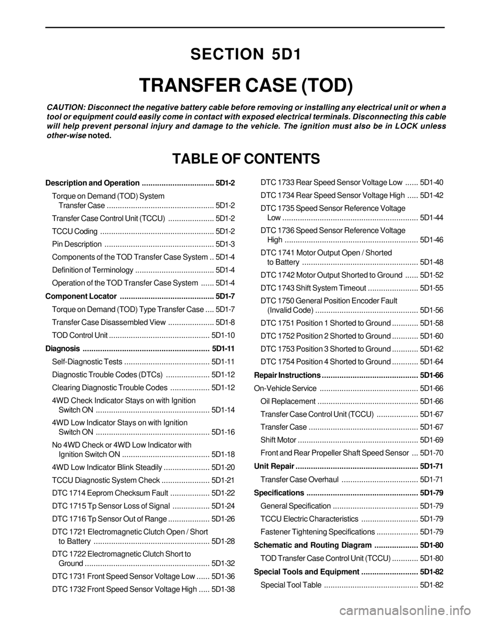
SECTION 5D1
TRANSFER CASE (TOD)
CAUTION: Disconnect the negative battery cable before removing or installing any electrical unit or when a
tool or equipment could easily come in contact with exposed electrical terminals. Disconnecting this cable
will help prevent personal injury and damage to the vehicle. The ignition must also be in LOCK unless
other-wise noted.
TABLE OF CONTENTS
Description and Operation.................................5D1-2
Torque on Demand (TOD) System
Transfer Case.................................................5D1-2
Transfer Case Control Unit (TCCU).....................5D1-2
TCCU Coding....................................................5D1-2
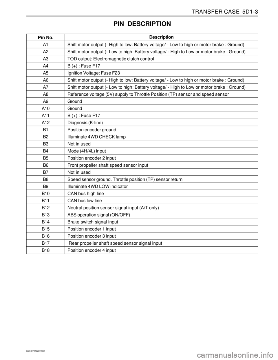
Pin Description..................................................5D1-3
Components of the TOD Transfer Case System ..5D1-4
Definition of Terminology....................................5D1-4
Operation of the TOD Transfer Case System......5D1-4
Component Locator...........................................5D1-7
Torque on Demand (TOD) Type Transfer Case....5D1-7
Transfer Case Disassembled View.....................5D1-8
TOD Control Unit..............................................5D1-10
Diagnosis..........................................................5D1-11
Self-Diagnostic Tests.......................................5D1-11
Diagnostic Trouble Codes (DTCs)....................5D1-12
Clearing Diagnostic Trouble Codes..................5D1-12
4WD Check Indicator Stays on with Ignition
Switch ON....................................................5D1-14
4WD Low Indicator Stays on with Ignition
Switch ON....................................................5D1-16
No 4WD Check or 4WD Low Indicator with
Ignition Switch ON........................................5D1-18
4WD Low Indicator Blink Steadily.....................5D1-20
TCCU Diagnostic System Check......................5D1-21
DTC 1714 Eeprom Checksum Fault..................5D1-22
DTC 1715 Tp Sensor Loss of Signal.................5D1-24
DTC 1716 Tp Sensor Out of Range...................5D1-26
DTC 1721 Electromagnetic Clutch Open / Short
to Battery.....................................................5D1-28
DTC 1722 Electromagnetic Clutch Short to
Ground.........................................................5D1-32
DTC 1731 Front Speed Sensor Voltage Low......5D1-36
DTC 1732 Front Speed Sensor Voltage High.....5D1-38DTC 1733 Rear Speed Sensor Voltage Low......5D1-40
DTC 1734 Rear Speed Sensor Voltage High.....5D1-42
DTC 1735 Speed Sensor Reference Voltage
Low ..............................................................5D1-44
DTC 1736 Speed Sensor Reference Voltage
High.............................................................5D1-46
DTC 1741 Motor Output Open / Shorted
to Battery.....................................................5D1-48
DTC 1742 Motor Output Shorted to Ground......5D1-52
DTC 1743 Shift System Timeout.......................5D1-55
DTC 1750 General Position Encoder Fault
(Invalid Code)...............................................5D1-56
DTC 1751 Position 1 Shorted to Ground............5D1-58
DTC 1752 Position 2 Shorted to Ground............5D1-60
DTC 1753 Position 3 Shorted to Ground............5D1-62
DTC 1754 Position 4 Shorted to Ground............5D1-64
Repair Instructions............................................5D1-66
On-Vehicle Service.............................................5D1-66
Oil Replacement..............................................5D1-66
Transfer Case Control Unit (TCCU)...................5D1-67
Transfer Case..................................................5D1-67
Shift Motor.......................................................5D1-69
Front and Rear Propeller Shaft Speed Sensor ...5D1-70
Unit Repair........................................................5D1-71
Transfer Case Overhaul...................................5D1-71
Specifications...................................................5D1-79
General Specification.......................................5D1-79
TCCU Electric Characteristics..........................5D1-79
Fastener Tightening Specifications...................5D1-79
Schematic and Routing Diagram....................5D1-80
TOD Transfer Case Control Unit (TCCU)............5D1-80
Special Tools and Equipment..........................5D1-82
Special Tool Table ...........................................5D1-82
Page 1373 of 2053

TRANSFER CASE 5D1-3
SSANGYONG MY2002
A1
A2
A3
A4
A5
A6
A7
A8
A9
A10
A11
A12
B1
B2
B3
B4
B5
B6
B7
B8
B9
B10
B11
B12
B13
B14
B15
B16
B17
B18Shift motor output (- High to low: Battery voltage/ - Low to high or motor brake : Ground)
Shift motor output (- Low to high: Battery voltage/ - High to Low or motor brake : Ground)
TOD output: Electromagnetic clutch control
B (+) : Fuse F17
Ignition Voltage: Fuse F23
Shift motor output (- High to low: Battery voltage/ - Low to high or motor brake : Ground)
Shift motor output (- Low to high: Battery voltage/ - High to Low or motor brake : Ground)
Reference voltage (5V) supply to Throttle Position (TP) sensor and speed sensor
Ground
Ground
B (+) : Fuse F17
Diagnosis (K-line)
Position encoder ground
Illuminate 4WD CHECK lamp
Not in used
Mode (4H/4L) input
Position encoder 2 input
Front propeller shaft speed sensor input
Not in used
Speed sensor ground. Throttle position (TP) sensor return
Illuminate 4WD LOW indicator
CAN bus high line
CAN bus low line
Neutral position sensor signal input (A/T only)
ABS operation signal (ON/OFF)
Brake switch signal input
Position encoder 1 input
Position encoder 3 input
Rear propeller shaft speed sensor signal input
Position encoder 4 input
PIN DESCRIPTION
Pin No.Description
Page 1374 of 2053

SSANGYONG MY2002
5D1-4 TRANSFER CASE
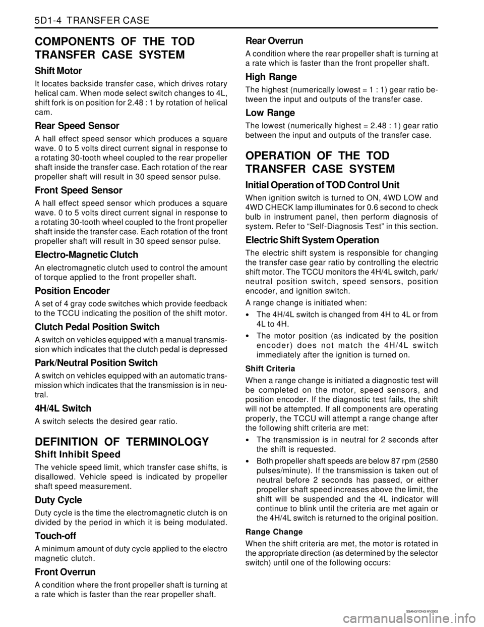
COMPONENTS OF THE TOD
TRANSFER CASE SYSTEM
Shift Motor
It locates backside transfer case, which drives rotary
helical cam. When mode select switch changes to 4L,
shift fork is on position for 2.48 : 1 by rotation of helical
cam.
Rear Speed Sensor
A hall effect speed sensor which produces a square
wave. 0 to 5 volts direct current signal in response to
a rotating 30-tooth wheel coupled to the rear propeller
shaft inside the transfer case. Each rotation of the rear
propeller shaft will result in 30 speed sensor pulse.
Front Speed Sensor
A hall effect speed sensor which produces a square
wave. 0 to 5 volts direct current signal in response to
a rotating 30-tooth wheel coupled to the front propeller
shaft inside the transfer case. Each rotation of the front
propeller shaft will result in 30 speed sensor pulse.
Electro-Magnetic Clutch
An electromagnetic clutch used to control the amount
of torque applied to the front propeller shaft.
Position Encoder
A set of 4 gray code switches which provide feedback
to the TCCU indicating the position of the shift motor.
Clutch Pedal Position Switch
A switch on vehicles equipped with a manual transmis-
sion which indicates that the clutch pedal is depressed
Park/Neutral Position Switch
A switch on vehicles equipped with an automatic trans-
mission which indicates that the transmission is in neu-
tral.
4H/4L Switch
A switch selects the desired gear ratio.
DEFINITION OF TERMINOLOGY
Shift Inhibit Speed
The vehicle speed limit, which transfer case shifts, is
disallowed. Vehicle speed is indicated by propeller
shaft speed measurement.
Duty Cycle
Duty cycle is the time the electromagnetic clutch is on
divided by the period in which it is being modulated.
Touch-off
A minimum amount of duty cycle applied to the electro
magnetic clutch.
Front Overrun
A condition where the front propeller shaft is turning at
a rate which is faster than the rear propeller shaft.
Rear Overrun
A condition where the rear propeller shaft is turning at
a rate which is faster than the front propeller shaft.
High Range
The highest (numerically lowest = 1 : 1) gear ratio be-
tween the input and outputs of the transfer case.
Low Range
The lowest (numerically highest = 2.48 : 1) gear ratio
between the input and outputs of the transfer case.
OPERATION OF THE TOD
TRANSFER CASE SYSTEM
Initial Operation of TOD Control Unit
When ignition switch is turned to ON, 4WD LOW and
4WD CHECK lamp illuminates for 0.6 second to check
bulb in instrument panel, then perform diagnosis of
system. Refer to “Self-Diagnosis Test” in this section.
Electric Shift System Operation
The electric shift system is responsible for changing
the transfer case gear ratio by controlling the electric
shift motor. The TCCU monitors the 4H/4L switch, park/
neutral position switch, speed sensors, position
encoder, and ignition switch.
A range change is initiated when:
The 4H/4L switch is changed from 4H to 4L or from
4L to 4H.
The motor position (as indicated by the position
encoder) does not match the 4H/4L switch
immediately after the ignition is turned on.
Shift Criteria
When a range change is initiated a diagnostic test will
be completed on the motor, speed sensors, and
position encoder. If the diagnostic test fails, the shift
will not be attempted. If all components are operating
properly, the TCCU will attempt a range change after
the following shift criteria are met:
The transmission is in neutral for 2 seconds after
the shift is requested.
Both propeller shaft speeds are below 87 rpm (2580
pulses/minute). If the transmission is taken out of
neutral before 2 seconds has passed, or either
propeller shaft speed increases above the limit, the
shift will be suspended and the 4L indicator will
continue to blink until the criteria are met again or
the 4H/4L switch is returned to the original position.
Range Change
When the shift criteria are met, the motor is rotated in
the appropriate direction (as determined by the selector
switch) until one of the following occurs:
Page 1375 of 2053

TRANSFER CASE 5D1-5
SSANGYONG MY2002
The motor reaches its destination.
The motor is on for 5 seconds without reaching its
destination. The shift has failed and the TCCU will
respond as default mode.
A fault occurs with either the motor or position
encoder. Refer to the diagnosis requirement.
When the motor is energized, the Ignition, 4H/4L
switch, propeller shaft speeds, and transmission
neutral inputs are ignored.
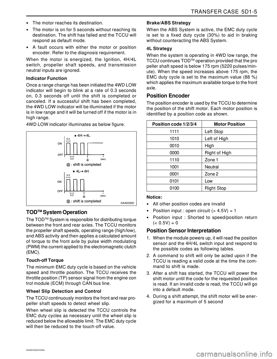
Indicator Function
Once a range change has been initiated the 4WD LOW
indicator will begin to blink at a rate of 0.3 seconds
on, 0.3 seconds off until the shift is completed or
canceled. If a successful shift has been completed,
the 4WD LOW indicator will be illuminated if the motor
is in low range and it will be turned off if the motor is in
high range.
4WD LOW indicator illuminates as below figure.
KAA5D000
TODTM System Operation
The TODTM System is responsible for distributing torque
between the front and rear axles. The TCCU monitors
the propeller shaft speeds, operating range (high/low),
and ABS activity and then applies a calculated amount
of torque to the front axle by pulse width modulating
(PWM) the current applied to the electromagnetic clutch
(EMC).
Touch-off Torque
The minimum EMC duty cycle is based on the vehicle
speed and throttle position. The TCCU receives the
throttle position (TP) sensor signal from the engine con
trol module (ECM) through CAN bus line.
Wheel Slip Detection and Control
The TCCU continuously monitors the front and rear pro-
peller shaft speeds to detect wheel slip.
When wheel slip is detected the TCCU controls the
EMC duty cycles as necessary until the wheel slip is
reduced below the allowable limit. The EMC duty cycle
will then be reduced to the touch-off value.Brake/ABS Strategy
When the ABS System is active, the EMC duty cycle
is set to a fixed duty cycle (30%) to aid in braking
without counteracting the ABS System.
4L Strategy
When the system is operating in 4WD low range, the
TCCU continues TOD
TM operation provided that the pro
peller shaft speed is below 175 rpm (5220 pulses/min-
ute). When the speed increases above 175 rpm, the
EMC duty cycle is set to the maximum value (88 %)
which applies the maximum available torque to the front
axle.
Position Encoder
The position encoder is used by the TCCU to determine
the position of the shift motor. Each motor position is
identified by a position code as shown.
Motor Position
Left Stop
Left of High
High
Right of High
Zone 1
Neutral
Zone 2
Low
Right Stop Position code 1/2/3/4
1111
1010
0010
0000
1110
1001
0001
0101
0100
Notice:
All other position codes are invalid
Position input : open circuit (> 4.5V) = 1
Position input : Shorted to speed/position return
(< 0.5V) = 0
Position Sensor Interpretation
1. When the module powers up, it will read the position
sensor and the 4H/4L switch input and respond to
the possible codes as following tables.
2. A command to shift will only be acted upon if the
TCCU is reading a valid code at the time the com-
mand to shift is made.
3. After a shift has started, the TCCU will power the
shift motor until the code for the requested position
is read. If an invalid code is read, the TCCU will go
into a default mode.
4. During a shift attempt, the shift motor will be ener-
gized for a maximum of 5 second
Page 1384 of 2053

SSANGYONG MY2002
5D1-14 TRANSFER CASE
4WD CHECK INDICATOR STAYS ON WITH IGNITION SWITCH ON
KAA5D040
Circuit Description
When the ignition switch turns to ON the transfer case
control unit (TCCU) illuminates 4WD CHECK and 4WD
LOWindicator to check bulb operation and turns off
after 0.6 seconds. Then TCCU starts self-diagnosis
and illuminate 4WD CHECK indicator when TCCU
detects any fault.
Diagnostic Aids
If the 4WD CHECK indicator illuminates steadily the
TCCU may detect some fault. TCCU should be
checked by scan tool to solve the problem.
The 4WD CHECK indicator also illuminates steadily
if the terminal B2 of TCCU connector is shorted to
ground. The shorted wire or terminals should be re-
paired.
Test Description
The number(s) below refer to step(s) on the diagnostic
table.
2. This step, along with step 4, checks the short to
ground condition of the wire or terminals
Step
1
ABS INDICATOR LAMP ILLUMINATED CONTINUOUSLY, NO DTCs STORED
Action Yes
Go to the
specific DTC
diagnostic tableNo
Go to Step 2 Value(s)
1. Turn the ignition switch to OFF.
2. Connect the scan tool to the data link connector
(DLC).
3. Turn the ignition switch to ON and request the DTC.
Does the scan tool display any DTC?
Page 1385 of 2053

TRANSFER CASE 5D1-15
SSANGYONG MY2002
Step
2
3
4
5Action
Yes
Go to Step 3
System OK
Go to Step 5
System OKNo
Go to Step 4
-
System OK
- Value(s)
1. Turn the ignition switch to OFF.
2. Disconnect the 18-pin connector from transfer case
control unit (TCCU).
3. Turn the ignition switch to ON and check the 4WD
CHECK bulb operation.
Does the 4WD CHECK indicator come on steadily?
Repair any short to ground circuit between terminal
B2 of TCCU connector and terminal A4 of cluster.
Is the repair complete?
1. Turn the ignition OFF.
2. Check the pin or terminals for damage or improper
connection.
3. Reconnect all the connectors.
4. Turn the ignition ON.
Does the 4WD CHECK indicator come on steadily?
Replace the TCCU.
Is the repair complete?