section 2c SSANGYONG KORANDO 1997 Service Repair Manual
[x] Cancel search | Manufacturer: SSANGYONG, Model Year: 1997, Model line: KORANDO, Model: SSANGYONG KORANDO 1997Pages: 2053, PDF Size: 88.33 MB
Page 1315 of 2053
MANUAL TRANSMISSION 5B-7
SSANGYONG MY2002
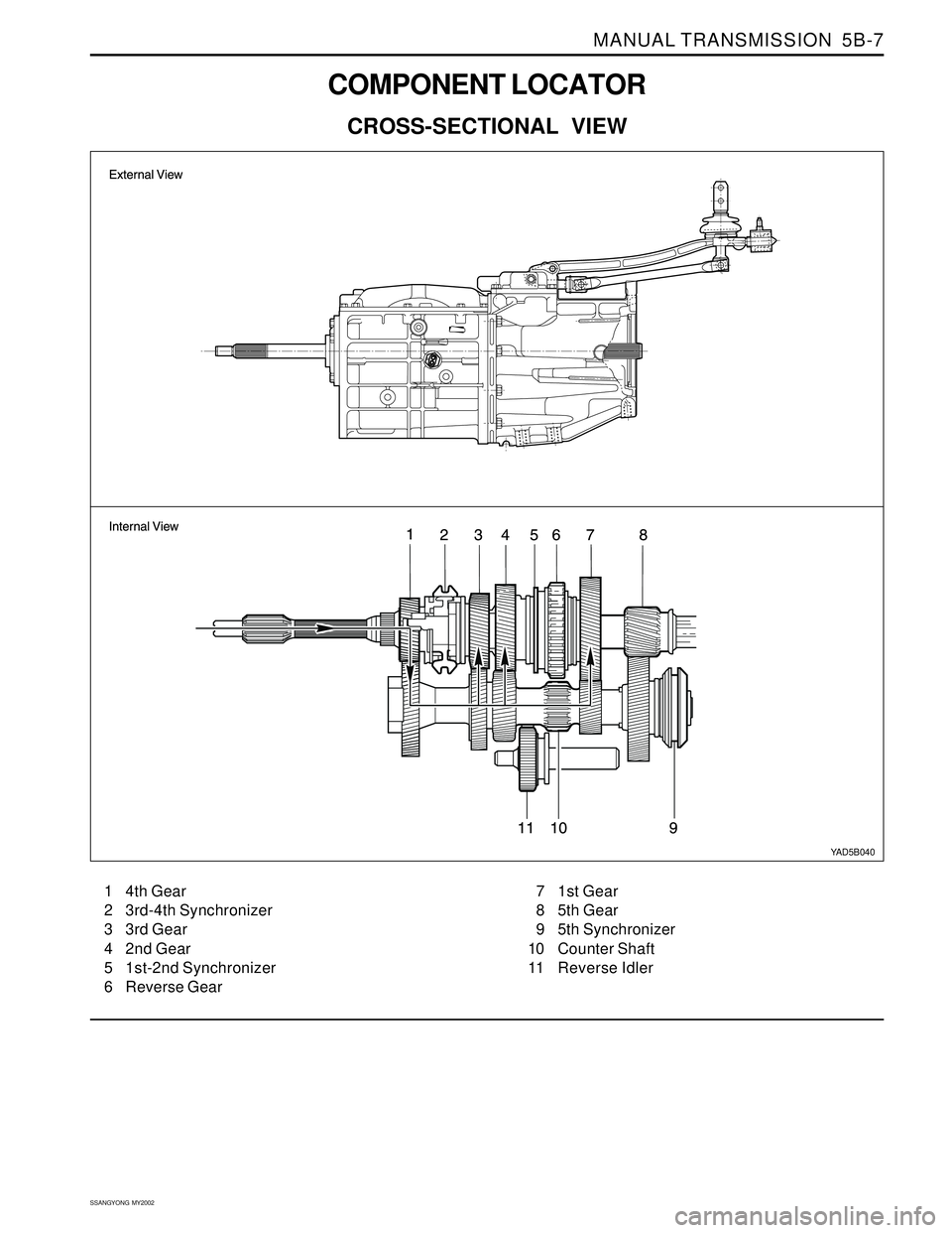
COMPONENT LOCATOR
CROSS-SECTIONAL VIEW
YAD5B040
1 4th Gear
2 3rd-4th Synchronizer
3 3rd Gear
4 2nd Gear
5 1st-2nd Synchronizer
6 Reverse Gear7 1st Gear
8 5th Gear
9 5th Synchronizer
10 Counter Shaft
11 Reverse Idler
Page 1357 of 2053
Specifications.......................................................5C-2
General Specifications.........................................5C-2
Fastener Tightening Specifications.......................5C-2
Component Locator.............................................5C-3
Clutch Assembly.................................................5C-3
Pedal and Master Cylinder...................................5C-4
Maintenance and Repair.....................................5C-5
On-Vehicle Service.................................................5C-5
Bleeding of Clutch System...................................5C-5
Clutch Disc......................................................... 5C- 6
Master Cylinder.................................................5C-10Clutch Pedal...................................................... 5C-12
Clutch Oil Chamber........................................... 5C-14
Diagnosis............................................................ 5C-15
Clutch Slips....................................................... 5C-15
Poor Disengagement ......................................... 5C-15
Hard to Shift or Will not Shift............................... 5C-15
Clutch Chatters When Starting........................... 5C-15
Difficult Pedal Operation.................................... 5C-16
Clutch Noisy...................................................... 5C-16
Special Tools and Equipment............................ 5C-17
Special Tools Table............................................ 5C-17
SECTION 5C
CLUTCH
CAUTION: Disconnect the negative battery cable before removing or installing any electrical unit or when a
tool or equipment could easily come in contact with exposed electrical terminals. Disconnecting this cable
will help prevent personal injury and damage to the vehicle. The ignition must also be in LOCK unless
otherwise noted.
TABLE OF CONTENTS
Page 1372 of 2053
SECTION 5D1
TRANSFER CASE (TOD)
CAUTION: Disconnect the negative battery cable before removing or installing any electrical unit or when a
tool or equipment could easily come in contact with exposed electrical terminals. Disconnecting this cable
will help prevent personal injury and damage to the vehicle. The ignition must also be in LOCK unless
other-wise noted.
TABLE OF CONTENTS
Description and Operation.................................5D1-2
Torque on Demand (TOD) System
Transfer Case.................................................5D1-2
Transfer Case Control Unit (TCCU).....................5D1-2
TCCU Coding....................................................5D1-2
Pin Description..................................................5D1-3
Components of the TOD Transfer Case System ..5D1-4
Definition of Terminology....................................5D1-4
Operation of the TOD Transfer Case System......5D1-4
Component Locator...........................................5D1-7
Torque on Demand (TOD) Type Transfer Case....5D1-7
Transfer Case Disassembled View.....................5D1-8
TOD Control Unit..............................................5D1-10
Diagnosis..........................................................5D1-11
Self-Diagnostic Tests.......................................5D1-11
Diagnostic Trouble Codes (DTCs)....................5D1-12
Clearing Diagnostic Trouble Codes..................5D1-12
4WD Check Indicator Stays on with Ignition
Switch ON....................................................5D1-14
4WD Low Indicator Stays on with Ignition
Switch ON....................................................5D1-16
No 4WD Check or 4WD Low Indicator with
Ignition Switch ON........................................5D1-18
4WD Low Indicator Blink Steadily.....................5D1-20
TCCU Diagnostic System Check......................5D1-21
DTC 1714 Eeprom Checksum Fault..................5D1-22
DTC 1715 Tp Sensor Loss of Signal.................5D1-24
DTC 1716 Tp Sensor Out of Range...................5D1-26
DTC 1721 Electromagnetic Clutch Open / Short
to Battery.....................................................5D1-28
DTC 1722 Electromagnetic Clutch Short to
Ground.........................................................5D1-32
DTC 1731 Front Speed Sensor Voltage Low......5D1-36
DTC 1732 Front Speed Sensor Voltage High.....5D1-38DTC 1733 Rear Speed Sensor Voltage Low......5D1-40
DTC 1734 Rear Speed Sensor Voltage High.....5D1-42
DTC 1735 Speed Sensor Reference Voltage
Low ..............................................................5D1-44
DTC 1736 Speed Sensor Reference Voltage
High.............................................................5D1-46
DTC 1741 Motor Output Open / Shorted
to Battery.....................................................5D1-48
DTC 1742 Motor Output Shorted to Ground......5D1-52
DTC 1743 Shift System Timeout.......................5D1-55
DTC 1750 General Position Encoder Fault
(Invalid Code)...............................................5D1-56
DTC 1751 Position 1 Shorted to Ground............5D1-58
DTC 1752 Position 2 Shorted to Ground............5D1-60
DTC 1753 Position 3 Shorted to Ground............5D1-62
DTC 1754 Position 4 Shorted to Ground............5D1-64
Repair Instructions............................................5D1-66
On-Vehicle Service.............................................5D1-66
Oil Replacement..............................................5D1-66
Transfer Case Control Unit (TCCU)...................5D1-67
Transfer Case..................................................5D1-67
Shift Motor.......................................................5D1-69
Front and Rear Propeller Shaft Speed Sensor ...5D1-70
Unit Repair........................................................5D1-71
Transfer Case Overhaul...................................5D1-71
Specifications...................................................5D1-79
General Specification.......................................5D1-79
TCCU Electric Characteristics..........................5D1-79
Fastener Tightening Specifications...................5D1-79
Schematic and Routing Diagram....................5D1-80
TOD Transfer Case Control Unit (TCCU)............5D1-80
Special Tools and Equipment..........................5D1-82
Special Tool Table ...........................................5D1-82
Page 1374 of 2053
SSANGYONG MY2002
5D1-4 TRANSFER CASE
COMPONENTS OF THE TOD
TRANSFER CASE SYSTEM
Shift Motor
It locates backside transfer case, which drives rotary
helical cam. When mode select switch changes to 4L,
shift fork is on position for 2.48 : 1 by rotation of helical
cam.
Rear Speed Sensor
A hall effect speed sensor which produces a square
wave. 0 to 5 volts direct current signal in response to
a rotating 30-tooth wheel coupled to the rear propeller
shaft inside the transfer case. Each rotation of the rear
propeller shaft will result in 30 speed sensor pulse.
Front Speed Sensor
A hall effect speed sensor which produces a square
wave. 0 to 5 volts direct current signal in response to
a rotating 30-tooth wheel coupled to the front propeller
shaft inside the transfer case. Each rotation of the front
propeller shaft will result in 30 speed sensor pulse.
Electro-Magnetic Clutch
An electromagnetic clutch used to control the amount
of torque applied to the front propeller shaft.
Position Encoder
A set of 4 gray code switches which provide feedback
to the TCCU indicating the position of the shift motor.
Clutch Pedal Position Switch
A switch on vehicles equipped with a manual transmis-
sion which indicates that the clutch pedal is depressed
Park/Neutral Position Switch
A switch on vehicles equipped with an automatic trans-
mission which indicates that the transmission is in neu-
tral.
4H/4L Switch
A switch selects the desired gear ratio.
DEFINITION OF TERMINOLOGY
Shift Inhibit Speed
The vehicle speed limit, which transfer case shifts, is
disallowed. Vehicle speed is indicated by propeller
shaft speed measurement.
Duty Cycle
Duty cycle is the time the electromagnetic clutch is on
divided by the period in which it is being modulated.
Touch-off
A minimum amount of duty cycle applied to the electro
magnetic clutch.
Front Overrun
A condition where the front propeller shaft is turning at
a rate which is faster than the rear propeller shaft.
Rear Overrun
A condition where the rear propeller shaft is turning at
a rate which is faster than the front propeller shaft.
High Range
The highest (numerically lowest = 1 : 1) gear ratio be-
tween the input and outputs of the transfer case.
Low Range
The lowest (numerically highest = 2.48 : 1) gear ratio
between the input and outputs of the transfer case.
OPERATION OF THE TOD
TRANSFER CASE SYSTEM
Initial Operation of TOD Control Unit
When ignition switch is turned to ON, 4WD LOW and
4WD CHECK lamp illuminates for 0.6 second to check
bulb in instrument panel, then perform diagnosis of
system. Refer to “Self-Diagnosis Test” in this section.
Electric Shift System Operation
The electric shift system is responsible for changing
the transfer case gear ratio by controlling the electric
shift motor. The TCCU monitors the 4H/4L switch, park/
neutral position switch, speed sensors, position
encoder, and ignition switch.
A range change is initiated when:
The 4H/4L switch is changed from 4H to 4L or from
4L to 4H.
The motor position (as indicated by the position
encoder) does not match the 4H/4L switch
immediately after the ignition is turned on.
Shift Criteria
When a range change is initiated a diagnostic test will
be completed on the motor, speed sensors, and
position encoder. If the diagnostic test fails, the shift
will not be attempted. If all components are operating
properly, the TCCU will attempt a range change after
the following shift criteria are met:
The transmission is in neutral for 2 seconds after
the shift is requested.
Both propeller shaft speeds are below 87 rpm (2580
pulses/minute). If the transmission is taken out of
neutral before 2 seconds has passed, or either
propeller shaft speed increases above the limit, the
shift will be suspended and the 4L indicator will
continue to blink until the criteria are met again or
the 4H/4L switch is returned to the original position.
Range Change
When the shift criteria are met, the motor is rotated in
the appropriate direction (as determined by the selector
switch) until one of the following occurs:
Page 1389 of 2053
TRANSFER CASE 5D1-67
SSANGYONG MY2002
KAA5D260
KAA5D270
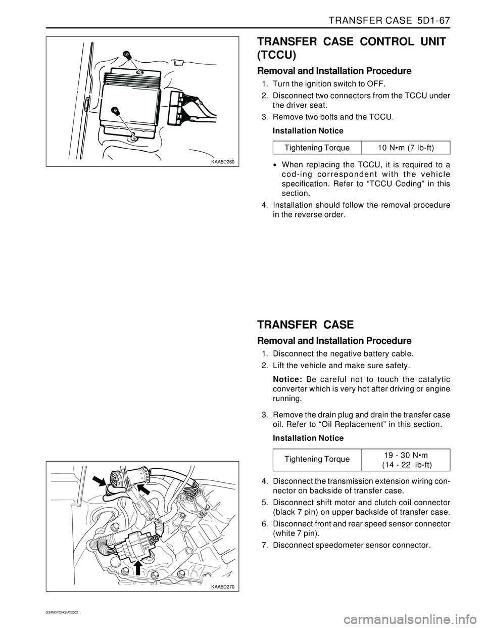
TRANSFER CASE CONTROL UNIT
(TCCU)
Removal and Installation Procedure
1. Turn the ignition switch to OFF.
2. Disconnect two connectors from the TCCU under
the driver seat.
3. Remove two bolts and the TCCU.
Installation Notice
Tightening Torque 10 Nm (7 lb-ft)
When replacing the TCCU, it is required to a
cod-ing correspondent with the vehicle
specification. Refer to “TCCU Coding” in this
section.
4. Installation should follow the removal procedure
in the reverse order.
TRANSFER CASE
Removal and Installation Procedure
1. Disconnect the negative battery cable.
2. Lift the vehicle and make sure safety.
Notice: Be careful not to touch the catalytic
converter which is very hot after driving or engine
running.
3. Remove the drain plug and drain the transfer case
oil. Refer to “Oil Replacement” in this section.
Installation Notice
4. Disconnect the transmission extension wiring con-
nector on backside of transfer case.
5. Disconnect shift motor and clutch coil connector
(black 7 pin) on upper backside of transfer case.
6. Disconnect front and rear speed sensor connector
(white 7 pin).
7. Disconnect speedometer sensor connector.
Tightening Torque19 - 30 Nm
(14 - 22 lb-ft)
Page 1393 of 2053
TRANSFER CASE 5D1-71
SSANGYONG MY2002
KAA5D360
KAA5D330
KAA5D380
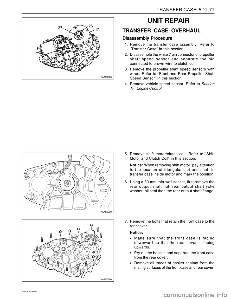
UNIT REPAIR
TRANSFER CASE OVERHAUL
Disassembly Procedure
1. Remove the transfer case assembly. Refer to
“Transfer Case” in this section.
2. Disassemble the white 7 pin connector of propeller
shaft speed sensor and separate the pin
connected to brown wire to clutch coil.
3. Remove the propeller shaft speed sensors with
wires. Refer to “Front and Rear Propeller Shaft
Speed Sensor” in this section.
4. Remove vehicle speed sensor. Refer to Section
1F, Engine Control.
7. Remove the bolts that retain the front case to the
rear cover.
Notice:
Make sure that the front case is facing
downward so that the rear cover is facing
upwards.
Pry on the bosses and separate the front case
from the rear cover.
Remove all traces of gasket sealant from the
mating surfaces of the front case and rear cover. 5. Remove shift motor/clutch coil. Refer to “Shift
Motor and Clutch Coil” in this section.
Notice: When removing shift motor, pay attention
to the location of triangular slot and shaft in
transfer case inside motor and mark the position.
6. Using a 30 mm thin-wall socket, first remove the
rear output shaft nut, rear output shaft yoke
washer, oil seal then the rear output shaft flange.
Page 1400 of 2053
SSANGYONG MY2002
5D1-78 TRANSFER CASE
31. Install the rear output shaft flange on rear output
shaft. Install the rubber seal, output shaft yoke
washer and nut. Tighten the nut and calk the nut
on the flat area.
Installation Notice
32. Install the shift motor. Refer to the “Shift Motor”
in this section.
33. Insert the brown wire and pin to speed sensor con-
nect and assemble the connector. Refer to “Front
and Rear Propeller Shaft Speed Sensors” in this
section.
34. Install the drain plug and tighten the drain plug.
Installation Notice
35. Fill the transfer case with 1.4 liters of ATF or equiva
lent.
Notice: Fluid level should be just below the filler
plug-hole.
36. Install the filler plug and tighten.
Installation Notice
37. Install the transfer case to the vehicle. Refer to
“Transfer Case” in the section.
5D380
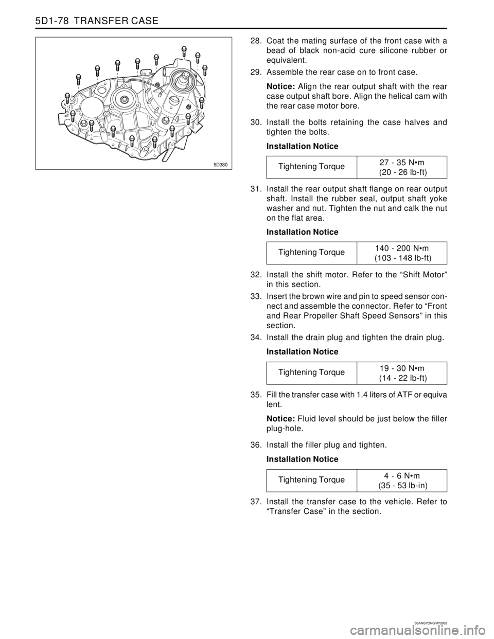
28. Coat the mating surface of the front case with a
bead of black non-acid cure silicone rubber or
equivalent.
29. Assemble the rear case on to front case.
Notice: Align the rear output shaft with the rear
case output shaft bore. Align the helical cam with
the rear case motor bore.
30. Install the bolts retaining the case halves and
tighten the bolts.
Installation Notice
Tightening Torque27 - 35 Nm
(20 - 26 lb-ft)
Tightening Torque140 - 200 Nm
(103 - 148 lb-ft)
Tightening Torque19 - 30 Nm
(14 - 22 lb-ft)
Tightening Torque4 - 6 Nm
(35 - 53 lb-in)
Page 1401 of 2053
SECTION 5D2
TRANSFER CASE (PART TIME - 4408)
TABLE OF CONTENTS
General Infromation and Operation..................5D2-2
4WD Operation Overview...................................5D2-2
System Structure...............................................5D2-3
2H Mode (Rear Wheel Drive)..............................5D2-5
4H Mode (4WD Drive - High Speed)...................5D2-6
4H Mode (4WD Drive - Low Speed)....................5D2-7
System Description...........................................5D2-8
Specifications....................................................5D2-9
Diagnostic Infromation and Procedures..........5D2-10
General Diagnosis...........................................5D2-10
Self-Diagnosis Test..........................................5D2-11
Diagnostic Diagram .........................................5D2-15
Component Locator .........................................5D2-16
Cross Sectional View.......................................5D2-16Transfer Case Assembly..................................5D2-17
Disassembly and Assembly............................5D2-18
Maintenance and Repair.................................5D2-20
On-Vehicle Service.............................................5D2-20
Maintenance of Transfer Case Lubricant...........5D2-20
4H and 4L Indicator .........................................5D2-21
TCCU Inspection.............................................5D2-21
Transfer Case Assembly..................................5D2-22
TCCU..............................................................5D2-24
Unit Repair........................................................5D2-25
Disassembly Procedure...................................5D2-25
Assembly Procedure.......................................5D2-35
Page 1415 of 2053

SSANGYONG MY2002
5D2-16 TRANSFER CASE (PART TIME - 4408)
� �
y y
����� �����
yyyyy yyyyy
�� ��
yy yy�� ��
yy yy
������ ������
������
������
yyyyyy yyyyyy
yyyyyy
yyyyyy
���� ����
����
yyyy yyyy
yyyy
��� ���
���
���
���
yyy yyy
yyy
yyy
yyy
������ ������ ������
yyyyyy yyyyyy yyyyyy
� �
y y
����� ����� �����
yyyyy yyyyy yyyyy
�� yy
���� yyyy
�� yy�� yy
� y��� �
y y
�� yy
�� yy
�� ��
��
yy yy
yy
�� yy�� yy
��� yyy
� y� �
y y
� �
y y�� yy
�� yy
�� yy
��� ���
yyy yyy� y� y
�� yy�� yy
�� yy
�� ��
yy yy
� y
�� ��
yy yy
�� ��
��
yy yy
yy
���� yyyy���������� ����������
yyyyyyyyyy yyyyyyyyyy
�� ��
yy yy�� ��
yy yy
� y��� y
�� ��
yy yy�� yy
�� ��
yy yy
��� ���
yyy yyy
� y
� �
y y
�� yy�� yy�� yy
��� ���
yyy yyy
� y� y
�� yy�� ��
yy yy�� yy�� ��
yy yy�� yy� y�� ��
yy yy
�� ��
��
yy yy
yy
� �
� y
� y
��� ���
���
yyy yyy
yyy��� yyy
������� yyyyyyy
� y
� y
�� yy�� ��
yy yy
�� yy�� yy
�� yy����� �����
�����
�����
�����
�����
yyyyy yyyyy
yyyyy
yyyyy
yyyyy
yyyyy
�� ��
yy yy
�� ��
yy yy
� y� y
� y
�� ��
yy yy
� y� y
�� ��
yy yy
�� ��
yy yy
� y� y
COMTONENT LOCATOR
CROSS SECTIONAL VIEW
KAA5D250
Page 1436 of 2053

TRANSFER CASE (PART TIME - 4408) 5D2-37
SSANGYONG MY2002
KAA5D810
KAA5D820
Adapter, Input Shaft and Carrier
1. Place the planet carrier assembly on work bench
to be the retaining ring mounting groove upward.
2. Install the sun gear with the hub end up into the
planet carrier assembly and rotate the sun gear
to make sure that gears are fully engaged.
3. Align the tabs and install the thrust plate into the
planet carrier assembly.
4. Install the retaining ring to the planet carrier
assembly.
5. Press the needle bearing into the input shaft and
press the new sleeve bearing into the input shaft
assembly.
6. Install the planet carrier assembly onto the input
shaft and install the thrust washer. Press the
bearing over input shaft.
7. After pressing the bearing, install the retaining
ring.
8. Press the pin into the front adapter.
9. Slowly press the oil seal into the front adapter.
10. Install the front adapter assembly.
Notice: After installation, make sure that snap ring
is correctly installed into the groove.
11. Position the input shaft assembly over front cover
and engage into the bearing groove by expanding
the ends of snap ring.
12. Apply 1.6mm bead of sealant on the mounting
face for the transfer case and tighten the 6 bolts.
13. Install the breather.
Installation Notice
Tightening Torque
28 - 40 Nm
(21 - 30 lb-ft)
4 - 7 Nm
(35 - 62 lb-in)
Item
6 Bolts
Breather
Front Output Shaft
Cross Sectional View