section 2c SSANGYONG KORANDO 1997 Service Owners Manual
[x] Cancel search | Manufacturer: SSANGYONG, Model Year: 1997, Model line: KORANDO, Model: SSANGYONG KORANDO 1997Pages: 2053, PDF Size: 88.33 MB
Page 1086 of 2053
ABS AND TCS 4F-103
SSANGYONG MY2002
UNIT REPAIR
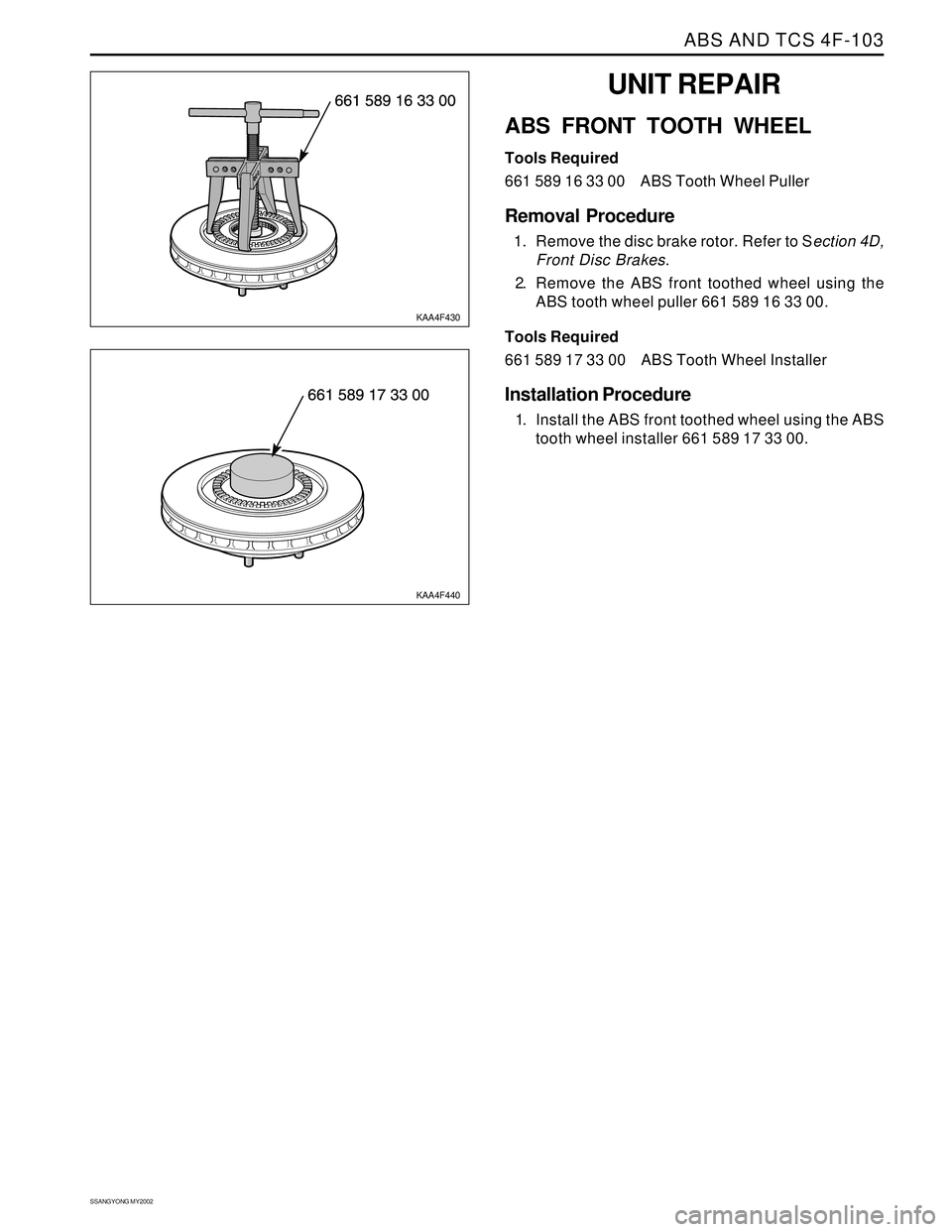
ABS FRONT TOOTH WHEEL
Tools Required
661 589 16 33 00 ABS Tooth Wheel Puller
Removal Procedure
1. Remove the disc brake rotor. Refer to Section 4D,
Front Disc Brakes.
2. Remove the ABS front toothed wheel using the
ABS tooth wheel puller 661 589 16 33 00.
Tools Required
661 589 17 33 00 ABS Tooth Wheel Installer
Installation Procedure
1. Install the ABS front toothed wheel using the ABS
tooth wheel installer 661 589 17 33 00.
KAA4F430
KAA4F440
Page 1088 of 2053
SECTION 4G
PARKING BRAKE
TABLE OF CONTENTS
Description and Operation..................................4G-2
Brake Caliper......................................................4G-2
Component Locator.............................................4G-3
Repair Instructions...............................................4G-4
On-Vehicle Service................................................4G-4Parking Brake Adjustment - Rear Disc Brakes.....4G-4
Parking Brake Lever............................................4G-5
Parking Brake Cable...........................................4G-6
Specifications......................................................4G-7
Fastener Tightening Specifications......................4G-7
Page 1091 of 2053
SSANGYONG MY2002
4G-4 PARKING BRAKE
KAA4G020
KAA4G030
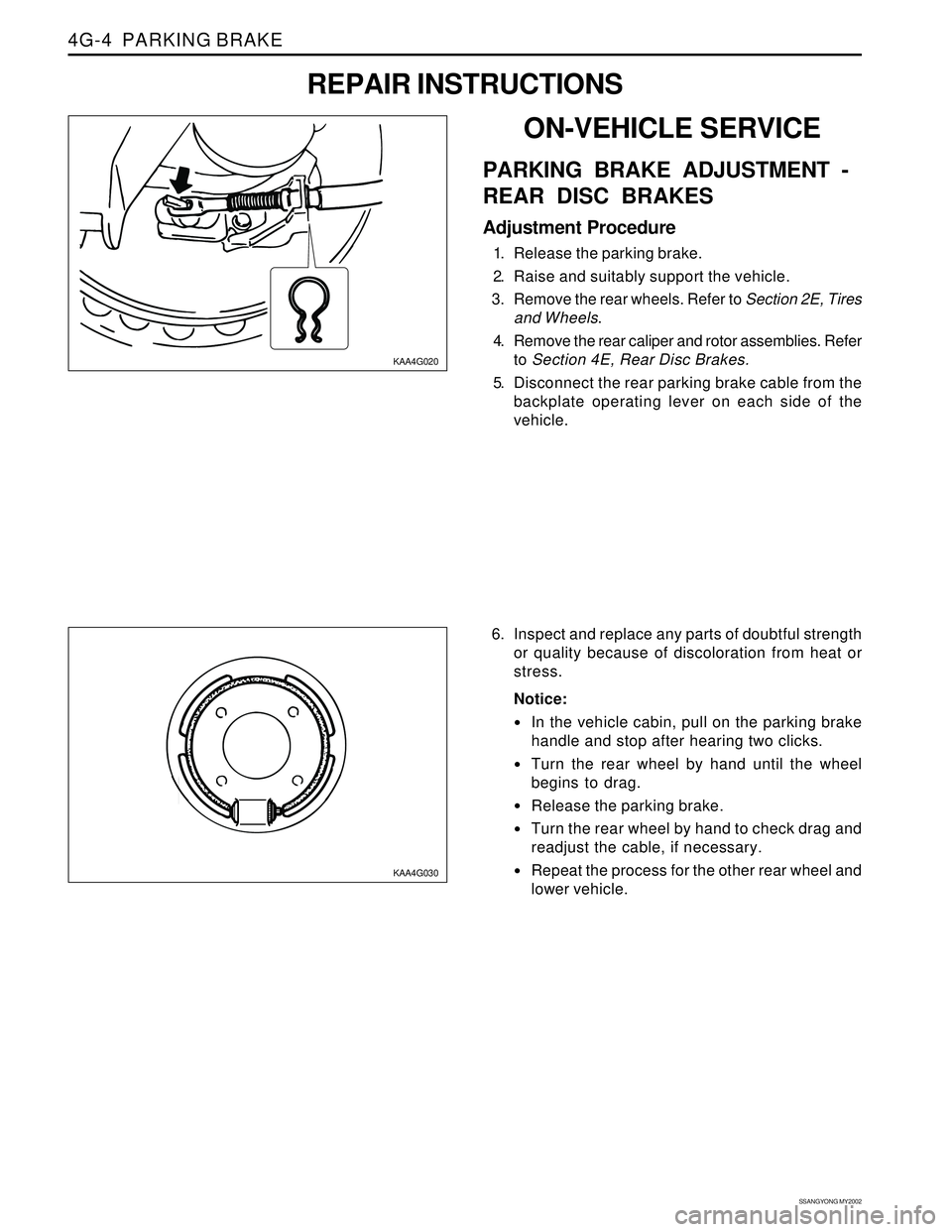
6. Inspect and replace any parts of doubtful strength
or quality because of discoloration from heat or
stress.
Notice:
In the vehicle cabin, pull on the parking brake
handle and stop after hearing two clicks.
Turn the rear wheel by hand until the wheel
begins to drag.
Release the parking brake.
Turn the rear wheel by hand to check drag and
readjust the cable, if necessary.
Repeat the process for the other rear wheel and
lower vehicle.
ON-VEHICLE SERVICE
PARKING BRAKE ADJUSTMENT -
REAR DISC BRAKES
Adjustment Procedure
1. Release the parking brake.
2. Raise and suitably support the vehicle.
3. Remove the rear wheels. Refer to Section 2E, Tires
and Wheels.
4. Remove the rear caliper and rotor assemblies. Refer
to Section 4E, Rear Disc Brakes.
5. Disconnect the rear parking brake cable from the
backplate operating lever on each side of the
vehicle.
REPAIR INSTRUCTIONS
Page 1092 of 2053
PARKING BRAKE 4G-5
SSANGYONG MY2002
KAA4G040
KAA4G050
KAA4G060
KAA4G070
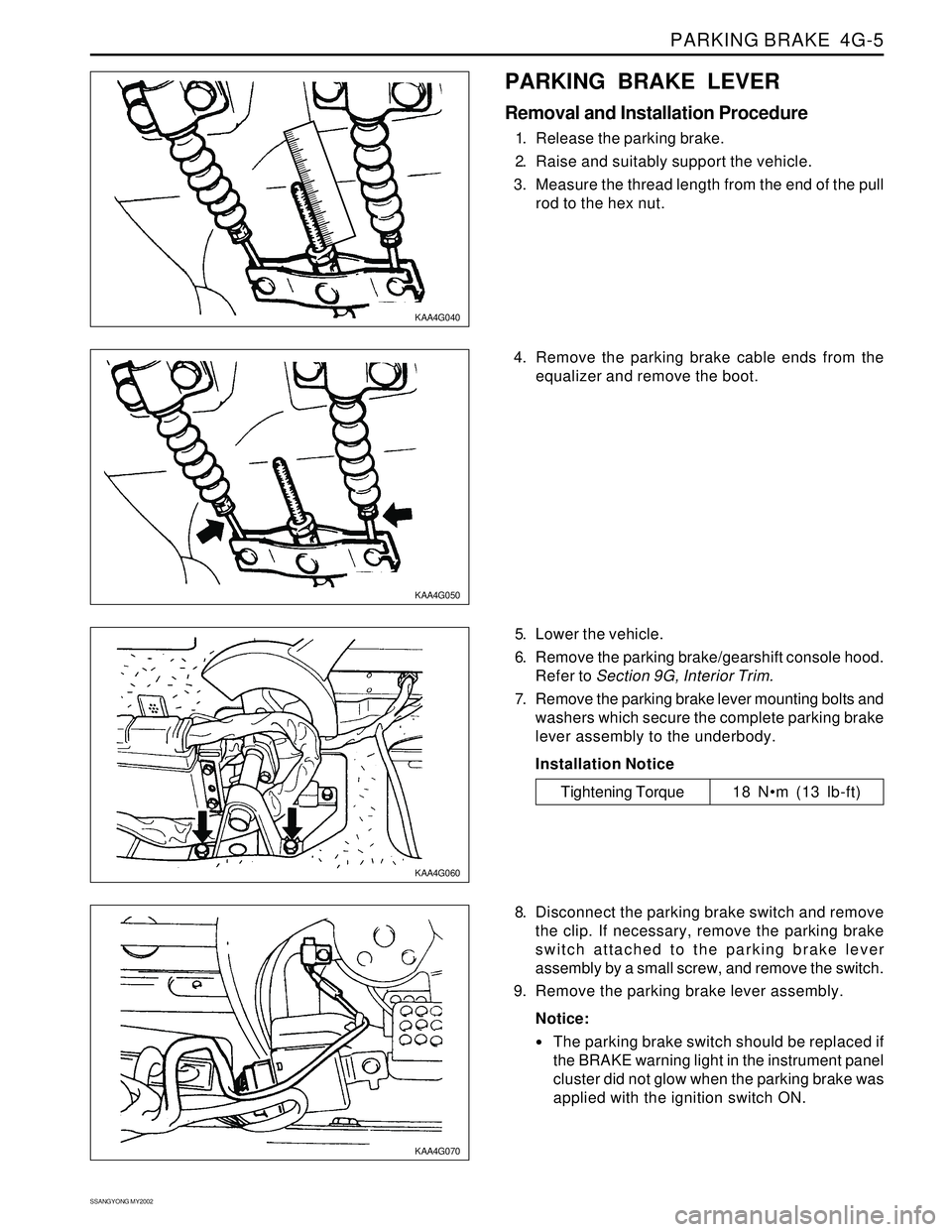
PARKING BRAKE LEVER
Removal and Installation Procedure
1. Release the parking brake.
2. Raise and suitably support the vehicle.
3. Measure the thread length from the end of the pull
rod to the hex nut.
5. Lower the vehicle.
6. Remove the parking brake/gearshift console hood.
Refer to Section 9G, Interior Trim.
7. Remove the parking brake lever mounting bolts and
washers which secure the complete parking brake
lever assembly to the underbody.
Installation Notice
8. Disconnect the parking brake switch and remove
the clip. If necessary, remove the parking brake
switch attached to the parking brake lever
assembly by a small screw, and remove the switch.
9. Remove the parking brake lever assembly.
Notice:
The parking brake switch should be replaced if
the BRAKE warning light in the instrument panel
cluster did not glow when the parking brake was
applied with the ignition switch ON.
Tightening Torque 18 Nm (13 lb-ft) 4. Remove the parking brake cable ends from the
equalizer and remove the boot.
Page 1095 of 2053
SECTION 5A
AUTOMATIC TRANSMISSION
CAUTION: Disconnect the negative battery cable before removing or installing any electrical unit or when a
tool or equipment could easily come in contact with exposed electrical terminals. Disconnecting this cable
will help prevent personal injury and damage to the vehicle. The ignition must also be in LOCK unless
otherwise noted.
TABLE OF CONTENTS
Description and Operation . . . . . . . . . . . . . . . . . 5A-2
BTRA M74 4WD Automatic Transmission . . . . . . 5A-2
Operators Interfaces . . . . . . . . . . . . . . . . . . . . . 5A-2
Control Systems . . . . . . . . . . . . . . . . . . . . . . . . 5A-3
Electronic Control System . . . . . . . . . . . . . . . . . 5A-3
Hydraulic Control System . . . . . . . . . . . . . . . . . . 5A-9
Hydraulic Control Circuit . . . . . . . . . . . . . . . . . . 5A-10
Power Train System . . . . . . . . . . . . . . . . . . . . . 5A-14
Power Flows . . . . . . . . . . . . . . . . . . . . . . . . . . 5A-18
Park and Neutral . . . . . . . . . . . . . . . . . . . . . . . 5A-20
Reverse . . . . . . . . . . . . . . . . . . . . . . . . . . . . . . 5A-22
Manual 1 . . . . . . . . . . . . . . . . . . . . . . . . . . . . . 5A-24
Drive 1 . . . . . . . . . . . . . . . . . . . . . . . . . . . . . . 5A-26
Drive 2 and Manual 2 . . . . . . . . . . . . . . . . . . . . 5A-28
Drive 3 and Manual 3 . . . . . . . . . . . . . . . . . . . . 5A-30
Drive 3 Lock Up and Manual 3 Lock Up . . . . . . 5A-32
Drive 4 (Overdrive) . . . . . . . . . . . . . . . . . . . . . 5A-34
Drive 4 Lock Up . . . . . . . . . . . . . . . . . . . . . . . . 5A-36
Diagnostic Information and Procedures . . . . . 5A-38
Diagnosis . . . . . . . . . . . . . . . . . . . . . . . . . . . . . 5A-38
Basic Knowledge Required . . . . . . . . . . . . . . . 5A-38
Functional Check Procedure . . . . . . . . . . . . . . . 5A-38
Transmission Fluid Level Service Procedure . . . 5A-38
Fluid Leak Diagnosis and Repair . . . . . . . . . . . 5A-39
Electrical / Garage Shift Test . . . . . . . . . . . . . . 5A-40
Road Test Procedure . . . . . . . . . . . . . . . . . . . . 5A-40
Electronic Adjustments . . . . . . . . . . . . . . . . . . 5A-40
Symptom Diagnosis . . . . . . . . . . . . . . . . . . . . . 5A-41
Drive Faults . . . . . . . . . . . . . . . . . . . . . . . . . . . 5A-41
Faulty Shift Pattern . . . . . . . . . . . . . . . . . . . . . . 5A-42Shift Quality Faults . . . . . . . . . . . . . . . . . . . . . . 5A-44
After Teardown Faults . . . . . . . . . . . . . . . . . . . 5A-46
Trouble Code Diagnosis - Gasoline Vehicle . . 5A-48
TCM Diagnostic System Overview . . . . . . . . . . 5A-48
Clearing Trouble Codes . . . . . . . . . . . . . . . . . . 5A-48
Diagnostic Trouble Codes . . . . . . . . . . . . . . . . 5A-48
Trouble Code Diagnosis - Diesel Vehicle . . . . . 5A-50
TCM Diagnostic System Overview . . . . . . . . . . 5A-50
Clearing Trouble Codes . . . . . . . . . . . . . . . . . . 5A-50
Diagnostic Trouble Codes . . . . . . . . . . . . . . . . 5A-50
Repair Instructions . . . . . . . . . . . . . . . . . . . . . . 5A-157
On-Vehicle Service . . . . . . . . . . . . . . . . . . . . . . . 5A-157
Transmission . . . . . . . . . . . . . . . . . . . . . . . . . . 5A-157
Unit Repair . . . . . . . . . . . . . . . . . . . . . . . . . . . . 5A-160
Rebuild Warnings . . . . . . . . . . . . . . . . . . . . . . 5A-160
Disassembly Procedure . . . . . . . . . . . . . . . . . . 5A-161
Assembly Procedure . . . . . . . . . . . . . . . . . . . . 5A-171
Front and Rear Band Adjustment . . . . . . . . . . . 5A-199
Gear Shift Control Lever . . . . . . . . . . . . . . . . . . 5A-202
Kickdown Switch . . . . . . . . . . . . . . . . . . . . . . . 5A-202
Specifications . . . . . . . . . . . . . . . . . . . . . . . . . . 5A-203
General Specification . . . . . . . . . . . . . . . . . . . . 5A-203
Fastener Tightening Specifications . . . . . . . . . . 5A-205
Schematic and Routing Diagrams . . . . . . . . . . 5A-206
TCM Wiring Diagrams (Gasoline Engine) . . . . . 5A-206
TCM Wiring Diagrams (Diesel Engine) . . . . . . . 5A-208
Connector End View . . . . . . . . . . . . . . . . . . . . . 5A-210
Special Tools and Equipment . . . . . . . . . . . . . 5A-211
Special Tools Table . . . . . . . . . . . . . . . . . . . . . 5A-211
Page 1098 of 2053
5A-4 AUTOMATIC TRANSMISSION
SSANGYONG MY2002
Output circuits which control external devices such
as the Variable Pressure Solenoid (VPS) driver, On/
Off solenoid drivers, a diagnostics output and the
driving mode indicator light.
Processing Logic
Shift schedule and calibration information is stored in
an Erasable Programmable Read Only Memory (EPROM).
Throttle input calibration constants and the diagnostics
information are stored in Electrically Erasable Program-
mable Read Only Memory (EEPROM) that retains the
memory even when power to the TCM is disconnected.
TCM continuously monitors the input values and uses
these, via the shift schedule, to determine the required
gear state. At the same time it monitors, via the solenoid
outputs, the current gear state, whenever the input
conditions change such that the required gear state is
different to the current gear state, the TCM initiates a
gear shift to bring the two states back into line.
Once the TCM has determined the type of gearshift
required the TCM accesses the shift logic, estimates
the engine torque output, adjusts the variable pressure
solenoid ramp pressure then executes the shift.The TCM continuously monitors every input and output
circuit for short or open circuits and operating range.
When a failure or abnormal operation is detected the
TCM records the condition code in the diagnostics
memory and implements a Limp Home Mode (LHM).
The actual limp home mode used depends upon the
failure detected with the object to maintain maximum
drive-ability without damaging the transmission. In
general input failures are handled by providing a default
value. Output failures, which are capable of damaging
the transmission, result in full limp mode giving only
third or fourth gear and reverse. For further details of
limp modes and memory retention refer to the
Diagnostic Trouble Code Diagnosis Section.
The TCM is designed to operate at ambient
temperatures between - 40 and 85 °C (- 40 and 185 °F).
It is also protected against electrical noise and voltage
spikes, however all the usual precautions should be
observed, for example when arc welding or jump
starting.
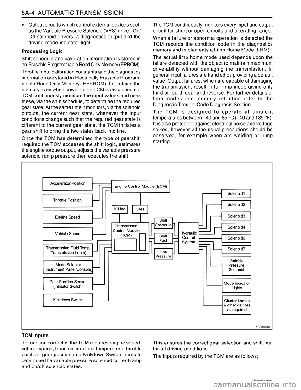
TCM Inputs
To function correctly, the TCM requires engine speed,
vehicle speed, transmission fluid temperature, throttle
position, gear position and Kickdown Switch inputs to
determine the variable pressure solenoid current ramp
and on/off solenoid states.
KAA5A030
This ensures the correct gear selection and shift feel
for all driving conditions.
The inputs required by the TCM are as follows;
Page 1106 of 2053
5A-12 AUTOMATIC TRANSMISSION
SSANGYONG MY2002
During a 4-3 gearshift, the C4 clutch is engaged and
the front band (B1) is released. These actions are se-
quenced by the 4-3 sequence valve.
The 3-4 shift valve also switches during 1-2 and 2-1
gearshifts where its function is to apply the overrun
clutch (C4) in second gear but to release it in first
gear.
Note that the C4 clutch is applied in Manual 1 by virtue
of the manual valve and the 1-2 shift valve. Refer to
“1-2 Shift Valve” in this section.
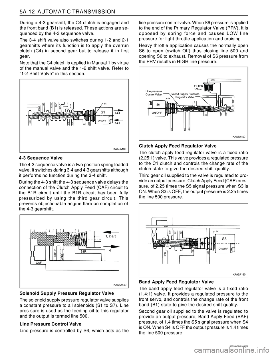
4-3 Sequence Valve
The 4-3 sequence valve is a two position spring loaded
valve. It switches during 3-4 and 4-3 gearshifts although
it performs no function during the 3-4 shift.
During the 4-3 shift the 4-3 sequence valve delays the
connection of the Clutch Apply Feed (CAF) circuit to
the B1R circuit until the B1R circuit has been fully
pressurized by using the third gear circuit. This
prevents objectionable engine flare on completion of
the 4-3 gearshift.
Solenoid Supply Pressure Regulator Valve
The solenoid supply pressure regulator valve supplies
a constant pressure to all solenoids (S1 to S7). Line
pres-sure is used as the feeding oil to this regulator
and the output is termed line 500.
Line Pressure Control Valve
Line pressure is controlled by S6, which acts as theline pressure control valve. When S6 pressure is applied
to the end of the Primary Regulator Valve (PRV), it is
opposed by spring force and causes LOW line
pressure for light throttle application and cruising.
Heavy throttle application causes the normally open
S6 to open (switch Off) thus closing line 500 and
opening S6 to exhaust. Removal of S6 pressure from
the PRV results in HIGH line pressure.
Clutch Apply Feed Regulator Valve
The clutch apply feed regulator valve is a fixed ratio
(2.25:1) valve. This valve provides a regulated pressure
to the C1 clutch and controls the change rate of the
clutch state to give the desired shift quality.
Third gear oil supplied to the valve is regulated to pro-
vide an output pressure, Clutch Apply Feed (CAF) pres-
sure, of 2.25 times the S5 signal pressure when S3 is
ON. When S3 is OFF, the output pressure is 2.25 times
the line 500 pressure.
Band Apply Feed Regulator Valve
The band apply feed regulator valve is a fixed ratio
(1.4:1) valve. It provides a regulated pressure to the
front servo, and controls the change rate of the front
band (B1) state to give the desired shift quality.
Second gear oil supplied to the valve is regulated to
provide an output pressure, Band Apply Feed (BAF)
pressure, of 1.4 times the S5 signal pressure when S4
is ON. When S4 is OFF the output pressure is 1.4 times
the line 500 pressure.
KAA5A160 KAA5A130
KAA5A150
KAA5A140
Page 1108 of 2053
5A-14 AUTOMATIC TRANSMISSION
SSANGYONG MY2002
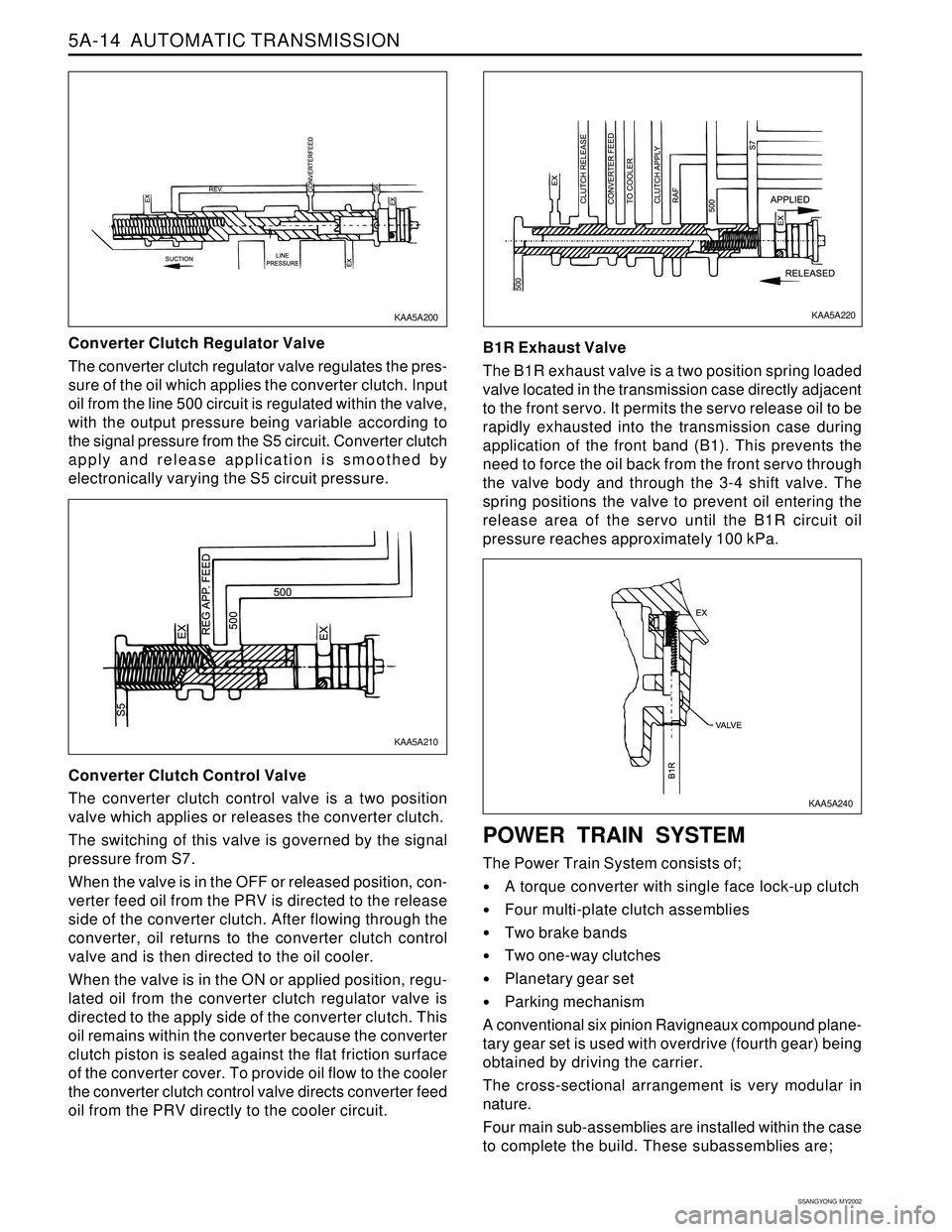
Converter Clutch Regulator Valve
The converter clutch regulator valve regulates the pres-
sure of the oil which applies the converter clutch. Input
oil from the line 500 circuit is regulated within the valve,
with the output pressure being variable according to
the signal pressure from the S5 circuit. Converter clutch
apply and release application is smoothed by
electronically varying the S5 circuit pressure.
Converter Clutch Control Valve
The converter clutch control valve is a two position
valve which applies or releases the converter clutch.
The switching of this valve is governed by the signal
pressure from S7.
When the valve is in the OFF or released position, con-
verter feed oil from the PRV is directed to the release
side of the converter clutch. After flowing through the
converter, oil returns to the converter clutch control
valve and is then directed to the oil cooler.
When the valve is in the ON or applied position, regu-
lated oil from the converter clutch regulator valve is
directed to the apply side of the converter clutch. This
oil remains within the converter because the converter
clutch piston is sealed against the flat friction surface
of the converter cover. To provide oil flow to the cooler
the converter clutch control valve directs converter feed
oil from the PRV directly to the cooler circuit.B1R Exhaust Valve
The B1R exhaust valve is a two position spring loaded
valve located in the transmission case directly adjacent
to the front servo. It permits the servo release oil to be
rapidly exhausted into the transmission case during
application of the front band (B1). This prevents the
need to force the oil back from the front servo through
the valve body and through the 3-4 shift valve. The
spring positions the valve to prevent oil entering the
release area of the servo until the B1R circuit oil
pressure reaches approximately 100 kPa.
POWER TRAIN SYSTEM
The Power Train System consists of;
A torque converter with single face lock-up clutch
Four multi-plate clutch assemblies
Two brake bands
Two one-way clutches
Planetary gear set
Parking mechanism
A conventional six pinion Ravigneaux compound plane-
tary gear set is used with overdrive (fourth gear) being
obtained by driving the carrier.
The cross-sectional arrangement is very modular in
nature.
Four main sub-assemblies are installed within the case
to complete the build. These subassemblies are;
KAA5A220KAA5A200
KAA5A210
KAA5A240
Page 1132 of 2053
5A-38 AUTOMATIC TRANSMISSION
SSANGYONG MY2002
DIAGNOSIS
BASIC KNOWLEDGE REQUIRED
You must be familliar with some basic electronics to
use this section of the Service Manual. They will help
you to follow diagnostic procedures.
Notice: Lack of the basic knowledge of this transmis-
sion when performing diagnostic procedures could re-
sult in incorrect diagnostic performance or damage to
transmission components. Do not, under any circum-
stances, attempt to diagnose a transmission problem
without this basic knowledge.
Notice: If a wire is probed with a sharp instrument
and not properly sealed afterward, the wire will corrode
and an open circuit will result.
Diagnostic test probes are now available that allow
you to probe individual wires without leaving the wire
open to the environment. These probe devices are
inexpensive and easy to install, and they permanently
seal the wire from corrosion.
Special Tools
You should be able to use a Digital Volt Meter (DVM),
a circuit tester, jumper wires or leads and a line
pressure gauge set. The functional check procedure
is designed to verify the correct operation of electronic
components in the transmission. This will eliminate the
unnecessary removal of transmission components.
FUNCTIONAL CHECK
PROCEDURE
Begin with the Functional Check Procedure which pro-
vides a general outline of how to diagnose automatic
transmission. The following functional check procedure
will indicate the proper path of diagnosing the transmis-
sion by describing the basic checks and then referenc-
ing the locations of the specific checks.
Check the fluid level according to the Fluid Level
Service Procedure.
Check the transmission fluid leak.
Check if the transmission fluid is not burnt by smell.
Notice: The specific fluid used in this transmission
turns brown during normal operation. Brown fluid
does not indicate a transmission fault.
Ensure that the transmission is not in Limp Home
Mode (LHM).
Check the battery terminals and the earth connec-
tions for corrosion or looseness.
Check that the cooler flow is not restricted.
Check all electrical plug connections for tightness.
Use on-board diagnostic tool or a scan tool to see
if any transmission trouble codes have been set.
DIAGNOSTIC INFORMATION AND PROCEDURES
Refer to the appropriate “Diagnostic Trouble Code
(DTC)” information and repair the vehicle as
directed. After repairing the vehicle, perform the
road test and verify that the code has not set again.
Perform the Electrical/Garage Shift Tests.
Perform the Road Test Procedure in this section.
Inspect the oil and check for metal or other contami-
nants in the oil pan.
TRANSMISSION FLUID LEVEL
SERVICE PROCEDURE
This procedure is to be used when checking a concern
with the fluid level in a vehicle. A low fluid level will
result in slipping and loss of drive/ reverse or delay on
engagement of drive/ reverse when the vehicle is cold.
The vehicle is first checked for transmission diagnostic
messages on the scan tool. If the oil level is low, it is
possible to register a vehicle speed signal fault.
The vehicle is to be test driven to determine if there is
an abnormal delay when selecting drive or reverse, or
loss of drive. One symptom of low fluid level is a
momentary loss of drive when driving the vehicle around
a corner. Also when the transmission fluid level is low,
a loss of drive may occur when the transmission fluid
temperature is low.
If there is no loss of drive when the vehicle is driven
warm and a vehicle speed signal fault is registered,
then fluid should be added to the transmission.
When adding or changing transmission fluid use only
Castrol TQ 95 automatic transmission fluid. The use of
incorrect fluid will cause the performance and durability
of the transmission to be severely degraded.
Fluid Level Diagnosis procedure
1. If the vehicle is at operating temperature allow the
vehicle to cool down for two hours, but no greater
than four hours. Or if the vehicle is at cool status,
start the engine and allow the engine to idle for
approximately 5 minutes or, if possible, drive the
vehicle for a few kilometers. This will allow the
transmission to be within the correct temperature
range. Transmission fluid level should be checked
at temperature 50 - 60 °C (82 - 140 °F).
Caution: Removal of the fluid filler plug when
the transmission fluid is hot may cause injury if
fluid drains from the filler hole.
2. With the brake pedal pressed, move the gear shift
control lever through the gear ranges, pausing a
few seconds in each range. Return the gear shift
control lever to P (Park). Turn the engine OFF.
3. Park the vehicle on a hoist, inspection pit or similar
raised level surface. The vehicle must be control
level to obtain a correct fluid level measurement.
Page 1143 of 2053
5A-48 AUTOMATIC TRANSMISSION
SSANGYONG MY2002
TROUBLE CODE DIAGNOSIS - GASOLINE VEHICLE
TCM DIAGNOSTIC SYSTEM
OVERVIEW
Notice: To prevent Transmission Control Module (TCM)
damage. The ignition key must be OFF when
disconnection or reconnection the power to the TCM
(for example bttery cable, TCM pigtail connector, TCM
fuse, jumper cables, etc.).
When the TCM detects a system fault, a Diagnostic
Trouble Code (DTC) is set in the TCM. This code is
present while the fault conditions are met and is stored
as a ‘History DTC’ until cleared. Condition for setting
and clearing each TCM DTC are provided in the relevant
sections.
In the case where the vehicle type is certified for Eure
On-Board Diagnostic (EOBD) compliance, the Engine
Control Module (ECM) provides the communication linkto the EOBD scan tool to pass on any EOBD relevant
codes from the TCM. The table below contains a list of
all supported DTCs and the classification of each for
EOBD purposes. Where a type B DTC has been set in
an EOBD vehicle, the response to the fault may include
action by the ECM, including the illumination of the
Malfunction lndicator Lamp (MIL). Refer to Section 1F,
Engine Control, for details on EOBD system function,
checks and fault clearing.
CLEARING TROUBLE CODES
TCM DTCs should be cleared after repairs have been
completed. Some diagnostic tables will tell you to clear
the codes before using the chart, which will help to
find the cause of the problem more quickly. Always
note the DTCs present before clearing - this information
may be helpful in the diagnostic process.”
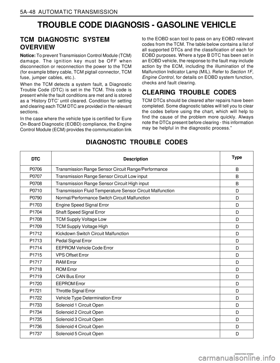
DIAGNOSTIC TROUBLE CODES
DTC
P0706
P0707
P0708
P0710
P0790
P1703
P1704
P1708
P1709
P1712
P1713
P1714
P1715
P1717
P1718
P1719
P1720
P1721
P1722
P1733
P1734
P1735
P1736
P1737Type
B
B
B
D
D
D
D
D
D
D
D
D
D
D
D
D
D
D
D
D
D
D
D
D Description
Transmission Range Sensor Circuit Range/Performance
Transmission Range Sensor Circuit Low input
Transmission Range Sensor Circuit High input
Transmission Fluid Temperature Sensor Circuit Malfunction
Normal/Performance Switch Circuit Malfunction
Engine Speed Signal Error
Shaft Speed Signal Error
TCM Supply Voltage Low
TCM Supply Voltage High
Kickdown Switch Circuit Malfunction
Pedal Signal Error
EEPROM Vehicle Code Error
VPS Offset Error
RAM Error
ROM Error
CAN Bus Error
EEPROM Error
Throttle Signal Error
Vehicle Type Determination Error
Solenoid 1 Circuit Open
Solenoid 2 Circuit Open
Solenoid 3 Circuit Open
Solenoid 4 Circuit Open
Solenoid 5 Circuit Open