SSANGYONG KORANDO 1997 Service Repair Manual
Manufacturer: SSANGYONG, Model Year: 1997, Model line: KORANDO, Model: SSANGYONG KORANDO 1997Pages: 2053, PDF Size: 88.33 MB
Page 1501 of 2053

POWER STEERING AND COLUMN 6E-15
SSANGYONG MY2002
SPECIAL TOOLS AND EQUIPMENT
SPECIAL TOOLS TABLE
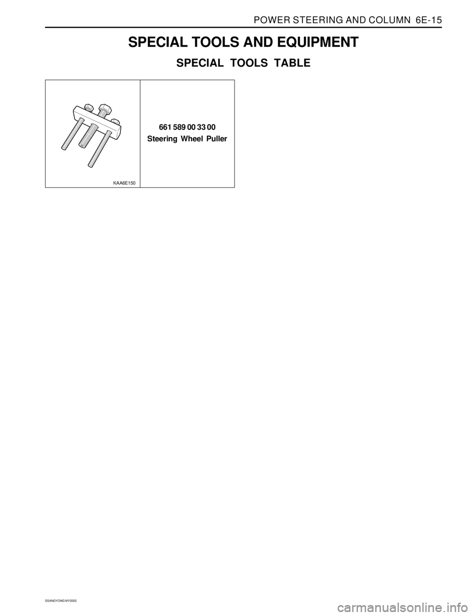
661 589 00 33 00
Steering Wheel Puller
KAA6E150
Page 1502 of 2053

SECTION 7A
HEATING AND VENTILATION SYSTEM
CAUTION: The cooling system is pressurized when hot. Injury can result from removing the coolant reservoir
cap before the engine is sufficiently cool.
TABLE OF CONTENTS
Description and Operation ................................7A-2
Heating and Ventilation System .........................7A-2
Components Locator ..........................................7A-3
Heater System ...................................................7A-3
Diagnostic Information and Procedures ..........7A-4
Heater System ...................................................7A-4
Blower Electrical ................................................7A-8
Mode Controls Do Not Work .............................7A-10
Air Source Selection Not Controlled ..................7A-12
Temperature Controls Do Not Work ..................7A-13
Too Much Heat .................................................7A-14
Blower Noise ....................................................7A-16
Repair Instructions ............................................7A-18
On-Vehicle Service..............................................7A-18
Temperature Control Cable Adjustment ............7A-18
Controller Assembly and Temperature
Control Cable .................................................7A-18
Control Assembly Knob Lighting ......................7A-19Air Intake Door Actuator ...................................7A-19
Mode Control Door Actuator .............................7A-20
Heater/Air Distributor Case Assembly ..............7A-20
Blower Motor ....................................................7A-21
Blower Resistor ................................................7A-22
Blower Unit .......................................................7A-22
Heater Inlet Hose ..............................................7A-23
Heater Outlet Hose ...........................................7A-23
Heater Core......................................................7A-24
Rear Heater Duct ..............................................7A-24
Air Filter ............................................................7A-24
Specifications .................................................... 7A-25
Heater Temperature Specification .....................7A-25
Heater Unit .......................................................7A-25
Fastener Tightening Specification .....................7A-25
Schematic and Routing Diagrams ................... 7A-26
Non - A/C Wiring Diagram ................................7A-26
Airflow Through Vents .......................................7A-28
Page 1503 of 2053

SSANGYONG MY2002
7A-2 HEATING AND VENTILATION SYSTEM
DESCRIPTION AND OPERATION
HEATING AND VENTILATION
SYSTEM
The base heater system is designed to provide heating,
ventilation, windshield defrosting, side wind defogging
and rear seat area.
The heater and fan assembly blower regulates the air-
flow from the air inlet for further processing and distribu-
tion.
The heater core transfers the heater from the engine
coolant to the inlet air.
The temperature door regulates the amount of the air
that passes through the heater core. The temperature
door also controls the temperature of the air by control-
ling mix of heated air with the ambient air.
The mode door regulates the flow and distribution of
the processed air to the heater ducts and to the defroster
ducts.
The console mounted heating and ventilation control
panel contains one rotary control knob, one sliding con-
trol lever and six push control knobs, which operate as
follows:
Sliding Temperature Control Lever
•Actuates by cable.
Raise the temperature of the air entering the vehicle
by sliding to the right, or the red portion of the knob.
Five Mode Control Knob
Actuates by electricity.
Regulates the air distribution between the
windshield, the instrument panel, and the floor
vents.
Rotary Blower Control Knob
Turns on to operate the blower motor at four speeds.
Turns OFF to stop the blower.
Operates completely independently from both the
mode control knob and temperature control knob.
Changes the fan speed in any mode and at any
speed.
Intake Air Control Knob
Operates by electricity.
Switches between recirculating the passenger
compartment air and bringing outside air into the
passenger compartment.
Is normally in fresh air mode.
Illuminates the indicator lamp when in the recalculat
ing mode.
Heater Core
The heater core heats the air before enters the vehicle.
Engine coolant is circulated through the core to heat
the outside air passing over the fins of the core. The
core is functional at all times and may be used to
temper conditioned air in the A/C mode as well as in
the heat or the vent mode.
Page 1504 of 2053

HEATING AND VENTILATION SYSTEM 7A-3
SSANGYONG MY2002
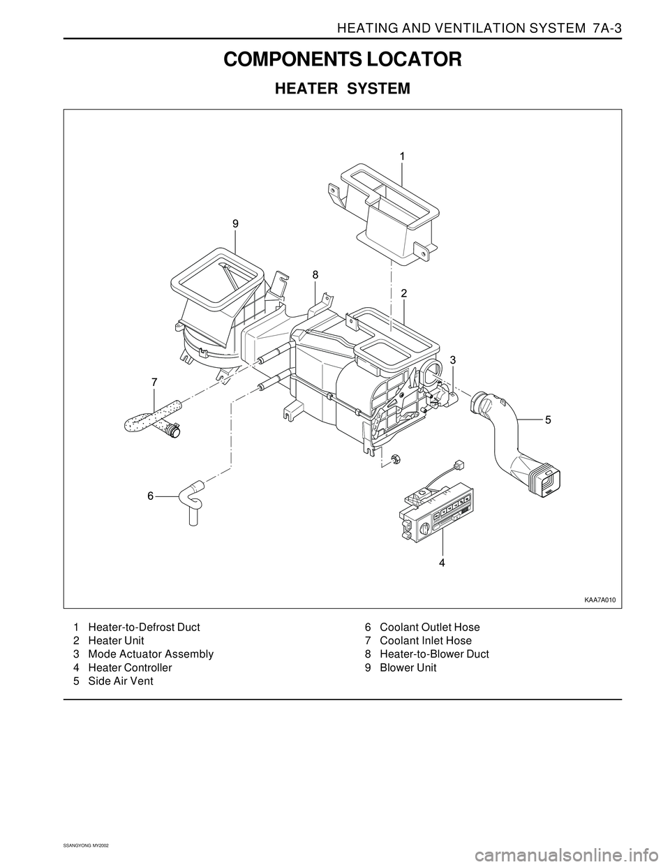
COMPONENTS LOCATOR
HEATER SYSTEM
1 Heater-to-Defrost Duct
2 Heater Unit
3 Mode Actuator Assembly
4 Heater Controller
5 Side Air Vent6 Coolant Outlet Hose
7 Coolant Inlet Hose
8 Heater-to-Blower Duct
9 Blower Unit
KAA7A010
Page 1505 of 2053

SSANGYONG MY2002
7A-4 HEATING AND VENTILATION SYSTEM
DIAGNOSTIC INFORMATION AND PROCEDURES
HEATER SYSTEM
Insufficient Heating or Defrosting
CAUTION: The cooling system is pressurized when hot. Injury can result from removing the coolant reservoir
cap before the engine is sufficiently cool.
Step
1
2
3
4
5
6
7
8
9
10
11
12
Action
Verify the customer’s complaint.
Are the customer’s concerns verified?
Check the coolant level.
Is the coolant level correct?
Add coolant as needed
Is the repair complete?
Check the serpentine accessory drive belt for tension
or damage.
Is the ’serpentine accessory drive belt OK?
Correct any problem with serpentine accessory drive
belt.
Is the repair complete?
Check the coolant hoses for leaks or kinks.
Are the coolant hoses OK?
Repair any problem with the coolant hoses.
Is the repair complete?
Check the coolant reservoir cap. Refer to Section 1D,
Engine Cooling.
Is the coolant reservoir cap OK?
Repair or replace the coolant reservoir cap as needed.
Is the repair complete?
1. Set the A/C switch OFF on the vehicles equipped
with air conditioning.
2. Set the temperature control lever to full hot.
3. Set the blower motor switch on 4.
4. Turn the ignition ON.
5. Check for the airflow from the vent outlet.
Is there a heavy airflow from the vent outlet?
Check for change in the airflow at various blower
speeds.
Does the blower speed increase as the switch is turned
from 1 to 4?
1. With the engine sufficiently cool, remove the
coolant reservoir cap.
2. Set the blower motor switch on 4.
3. Set the temperature control lever to full hot.
4. Start the engine and idle the engine.
5. Watch for the flow of the coolant.
Is the coolant flow visible?Yes
Go to Step 2
Go to Step 4
System OK
Go to Step 5
System OK
Go to Step 8
System OK
Go to Step 10
System OK
Go to Step 11
Go to Step 12
Go to Step 16No
System OK
Go to Step 3
Go to Step 4
Go to Step 6
Go to Step 6
Go to Step 7
Go to Step 8
Go to Step 9
Go to Step 10
Go to Step 25
Go to “Blower
Electrical”
Go to Step 13 Value(s)
-
Page 1506 of 2053

HEATING AND VENTILATION SYSTEM 7A-5
SSANGYONG MY2002
Insufficient Heating or Defrosting (Cont’d)
Step
13
14
15
16
17
18
19
20Action
Check the thermostat. Refer to Section 1D, Engine
Cooling.
Is the thermostat installed and seated properly?
Replace the thermostat. Refer to Section 1D, Engine
Cooling.
Is the repair complete?
Reinstall the thermostat.
Is the repair complete?
1. Install the coolant reservoir cap.
2. With the ignition ON, allow the engine to warm up
for about 20 minutes. Drive the vehicle at 48 km/h
(30 mph).
3. Use a thermometer to measure the ambient air
temperature and the discharge air temperature at
the heater outlet.
Does the heater output meet the minimum value
given?
1. Check the vehicle for cold air leaks at the following
locations:
Dash.
Heater case.
Vents.
2. Check under the seat for obstructions.
3. Repair any leaks or obstructions.
Are the repairs complete?
1. Turn the ignition OFF.
2. Turn the temperature control lever to full cold, then
rapidly to full hot.
3. Listen for a second of the end of travel range of the
control lever
Does the door slam?
1. Check the following aspects of the temperature
door:
Travel
Heater case
Vents
2. Verify the accuracy of the temperature controls at
full hot.
3. Verify the accuracy of the temperature controls at
full cold.
Is the repair complete?
1. Set the temperature door to full hot.
2. Start the vehicle
3. Check the temperature of the heater inlet hose and
the heater outlet hose by feel. The air temperature
around the hoses should be at least 29 °C (84 °F)
Is the heater inlet hose hot and heater outlet hose
warm?Yes
Go to Step 14
System OK
System OK
Go to Step 17
System OK
Go to Step 20
System OK
Go to Step 26No
Go to Step 15
-
-
Go to Step 18
-
Go to Step 19
-
Go to Step 21 Value(s)
Page 1507 of 2053

SSANGYONG MY2002
7A-6 HEATING AND VENTILATION SYSTEM
Insufficient Heating or Defrosting (Cont’d)
Step
21
22
23
24
25
26
27
28
29
30
31
32Action
Inspect heater hoses for proper installation.
Are heater hoses reversed?
Reinstall the heater hoses properly.
Is the repair complete?
1. Back flushes the heater core.
2. Drain the cooling system.
3. Replace the coolant.
4. Warm the engine to an average operating tem-
perature.
5. Feel the heater inlet hose and outlet hose.
Are the heater inlet hose hot and the heater outlet
hose warm?
Replace heater core.
Is the repair complete?
Recheck the system using the “Control setting/
Correct Results” tests. Refer to “Improper Air Delivery
or No Mode Shift” in this section.
Is the repair complete?
Check for airflow from the defroster or the vent
outlets.
Is there high airflow form the defroster or vent outlets?
Check the heater door at the floor and the vent door
to get proper airflow, verify proper operation, and
repair as required.
Is the repair complete?
Push the defroster knob
Is the defroster airflow OK?
1. Remove the heater outlet and check for obstruc-
tions.
2. Remove any obstructions in the heater outlet.
Is the repair complete?
Check for obstructions in the system at blower inlet
and the air filter, if the vehicle equipped with one.
Are there any obstructions?
Remove the obstructions in the system at the blower
inlet or replace a clogged filter.
Are the repairs complete?
1. Set the blower on 4.
2. Slide the temperature control lever from full hot to
full cold.
3. Listen for an airflow change.
Does the airflow change?Yes
Go to Step 22
System OK
System OK
System OK
System OK
Go to Step 27
System OK
Go to Step 29
System OK
Go to Step 31
System OK
Go to Step 33No
Go to Step 23
-
Go to Step 24
-
Go to Step 26
Go to Step 28
-
Go to Step 30
-
Go to Step 32
-
Go to Step 34 Value(s)
Page 1508 of 2053

HEATING AND VENTILATION SYSTEM 7A-7
SSANGYONG MY2002
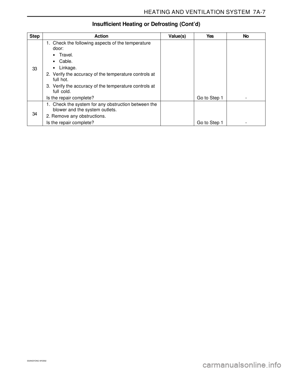
Insufficient Heating or Defrosting (Cont’d)
Step
33
34Action
1. Check the following aspects of the temperature
door:
Travel.
Cable.
Linkage.
2. Verify the accuracy of the temperature controls at
full hot.
3. Verify the accuracy of the temperature controls at
full cold.
Is the repair complete?
1. Check the system for any obstruction between the
blower and the system outlets.
2. Remove any obstructions.
Is the repair complete?Yes
Go to Step 1
Go to Step 1No
-
- Value(s)
Page 1509 of 2053

SSANGYONG MY2002
7A-8 HEATING AND VENTILATION SYSTEM
BLOWER ELECTRICAL
Refer to “Non A/C Diagrams” for electrical schematic diagram of the circuits described in this procedure.
Step
1
2
3
4
5
6
7
8
9
10
Action
Verify the customer’s complaint.
Are the customer’s concerns verified?
Does the blower run at any speed?
1. Disconnect the power connector from the blower
motor under the dashboard on the passenger side
of the vehicle.
2. Turn the ignition ON.
3. Turn the blower ON.
4. Test the voltage on the connector. The terminal
connected to the BLK/WHT wire is positive and
the terminal connected to the BLU/YEL wire is
negative.
Is the voltage within the specified range?
Replace the blower motor.
Is the repair complete?
Check fuse EF2 in the engine fuse block and F19 in
the I/P fuse block.
Is the fuse blown?
1. Turn the ignition ON.
2. Use a short detector to locate the following
possible short:
From the fuse EF2 to terminal 30 of blower
motor relay.
From the fuse F19 to terminal 86 of blower
motor relay.
From the terminal 87 of blower motor relay to
blower motor.
3. Repair any short.
4. Replace any blown fuse.
Is the repair complete?
1. Turn the ignition ON.
2. Remove the blower motor relay.
3. Using test light check the continuity between
following terminals and ground:
Terminal 30 of blower motor relay.
Terminal 86 of blower motor relay.
Does the test light come on?
Repair the open circuit.
Is the repair complete?
1. Turn the ignition OFF.
2. Set the blower motor switch at 4.
3. Using ohmmeter, measure the resistance between
terminal 85 of blower motor relay and ground.
Is the resistance within specified value?
Repair open circuit.
Is the repair complete?Yes
Go to Step 2
Go to Step 16
Go to Step 4
System OK
Go to Step 6
System OK
Go to Step 9
System OK
Go to Step 11
System OKNo
System OK
Go to Step 3
Go to Step 5
-
Go to Step 7
-
Go to Step 8
-
Go to Step 10
-
Value(s)
-
11 - 14 v
≈ 0 Ω
Page 1510 of 2053

HEATING AND VENTILATION SYSTEM 7A-9
SSANGYONG MY2002
Blower Electrical (Cont’d)
Step
11
12
13
14
15
16
17Action
Using ohmmeter, measure the resistance between
terminal 87 of blower motor relay.
Is the resistance within specified value?
Replace the blower motor relay.
Is the repair complete?
1. Disconnect blower motor switch connector.
2. Turn the ignition switch ON.
3. Jump terminal 5 and terminal 1 of the blower
motor switch connector with jump wire.
Does the blower motor run?
Repair open circuit between terminal 87 of blower
motor relay to ground G203.
Is the repair complete?
Replace the blower motor switch.
Is the repair complete?
1. Disconnect the blower motor switch connector.
2. Turn the ignition switch ON.
3. Using test light, check the power feed between
terminal 2, 3, 4, and 5 of the blower motor switch
connector and ground.
Does the light come on?
Repair open circuit or replace the blower resister.
Is the repair complete?Yes
Go to Step 12
System OK
Go to Step 15
System OK
System OK
Go to Step 15
System OKNo
Go to Step 13
-
Go to Step 7
-
-
Go to Step 17
-Value(s)
≈ 0 Ω