SSANGYONG KORANDO 1997 Service Repair Manual
KORANDO 1997
SSANGYONG
SSANGYONG
https://www.carmanualsonline.info/img/67/57502/w960_57502-0.png
SSANGYONG KORANDO 1997 Service Repair Manual
Trending: parking brake, octane, oil, brakes, ignition switch, tccu, radio antenna
Page 151 of 2053
M162 ENGINE COOLING 1D1 -- 15
D AEW OO M Y_2000
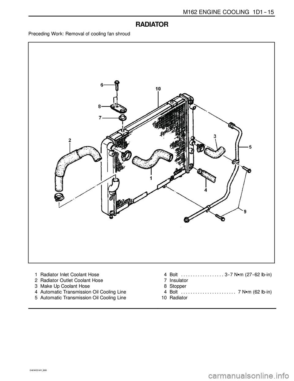
RADIATOR
Preceding Work: Removal of cooling fan shroud
1 Radiator Inlet Coolant Hose
2 Radiator Outlet Coolant Hose
3 Make Up Coolant Hose
4 Automatic Transmission Oil Cooling Line
5 Automatic Transmission Oil Cooling Line4Bolt 3--7NSm (27-- 62 lb-in) ..................
7 Insulator
8 Stopper
4Bolt 7NSm (62 lb-in) .......................
10 Radiator
Page 152 of 2053
1D1 -- 16 M162 ENGINE COOLING
D AEW OO M Y_2000
Removal & Installation Procedure
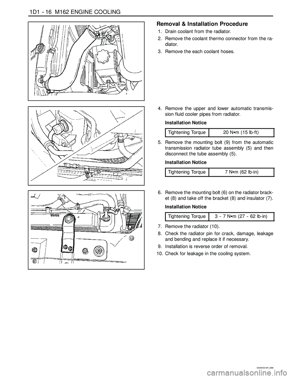
1. Drain coolant from the radiator.
2. Remove the coolant thermo connector from the ra-
diator.
3. Remove the each coolant hoses.
4. Remove the upper and lower automatic transmis-
sion fluid cooler pipes from radiator.
Installation Notice
Tightening Torque
20 NSm (15 lb-ft)
5. Remove the mounting bolt (9) from the automatic
transmission radiator tube assembly (5) and then
disconnect the tube assembly (5).
Installation Notice
Tightening Torque
7NSm(62lb-in)
6. Remove the mounting bolt (6) on the radiator brack-
et (8) and take off the bracket (8) and insulator (7).
Installation Notice
Tightening Torque
3--7NSm (27 -- 62 lb-in)
7. Remove the radiator (10).
8. Check the radiator pin for crack, damage, leakage
and bending and replace it if necessary.
9. Installation is reverse order of removal.
10. Check for leakage in the cooling system.
Page 153 of 2053

D AEW OO M Y_2000
SECTION 1E1
M162 ENGINE ELECTRICAL
CAUTION: Disconnect the negative battery cable before removing or installing any electrical unit or when a
tool or equipment could easily come in contact with exposed electrical terminals. Disconnecting this cable
will help prevent personal injury and damage to the vehicle. The ignition must also be in LOCK unless other -
wise noted.
TABLE OF CONTENTS
Specifications 1E1 -- 2............................
Generator Specifications 1E1-- 2..................
Starting Motor Specifications 1E1-- 2...............
Battery Specifications 1E1-- 2.....................
Fastener Tightening Specifications 1E1 -- 2..........
Maintenance and Repair 1E1 -- 3...................
On-- Vehicle Service 1E1-- 3.........................Generator 1E1-- 3...............................
Starting Motor 1E1--4...........................
Battery 1E1--5.................................
Spark Plug 1E1 -- 6..............................
Ignition Cable 1E1-- 8............................
Unit Repair 1E1 -- 11..............................
Battery 1E1--11.................................
Page 154 of 2053
1E 1 -- 2 M162 ENGINE ELECTRICAL
D AEW OO M Y_2000
SPECIFICATIONS
GENERATOR SPECIFICATIONS
ApplicationDescription
Current11 5 A
Output Voltage12 -- 14 v
Resistance Between Rotor Core and Slip Ring‚ąě‚Ą
STARTER SPECIFICATIONS
ApplicationDescription
Output Power1.8 kw
Voltage12 v
BATTERY SPECIFICATIONS
ApplicationDescription
Capacity90 AH
Max. Tolerance Between Cells‚Č•0.04
Specific Gravity‚Č•1.24
FASTER TIGHTENING SPECIFICATIONS
ApplicationNSmLb-FtLb-In
Generator Terminal B+Nut14 -- 1810 -- 13--
Generator Terminal D+Nut4--5--35 -- 44
Generator Mounting Bolt2518--
Battery Cable Nut on Starting Motor12 -- 159--11--
Electric Wire Nut on Starting Motor6--7--53 -- 62
Starting Motor Mounting Bolt35 -- 4826 -- 35--
Battery Mounting Bracket Nut12 -- 189--13--
Battery Negative Cable12 -- 189--13--
Battery Positive Cable12 -- 189--13--
Spark Plug Cover Bolt9--11--80 -- 97
Ignition Cable Bolt9--11--80 -- 97
Spark plug20 -- 3015 -- 22--
Page 155 of 2053
M162 ENGINE ELECTRICAL 1E 1 -- 3
D AEW OO M Y_2000
MAINTENANCE AND REPAIR
ON-VEHICLE SERVICE
GENERATOR
Preceding Work : Removal of the drivebelt
Removal & Installation Procedure
1. Disconnect the negative battery terminal.
2. Unscrew the nut and disconnect the terminal (1).
Installation Notice
Tightening Torque
14 -- 18 NSm (10 -- 13 lb-ft)
3. Unscrew the nut and disconnect the terminal (2).
Installation Notice
Tightening Torque
4--5NSm (35 -- 44 lb-in)
1 Terminal (B+)
2 Terminal (D+)
4. Unscrew the generator mounting bolt (3).
Installation Notice
Tightening Torque
25 NSm (18 lb-ft)
5. Remove the generator.
6. Installation should follow the removal procedure in
the reverse order.
3 Generator Mounting Bolt
4 Generator
Page 156 of 2053
1E 1 -- 4 M162 ENGINE ELECTRICAL
D AEW OO M Y_2000
STARTING MOTOR
Removal & Installation Procedure
1. Disconnect the ground cable.
2. Unscrew the nut and disconnect the battery cable(1).
Installation Notice
Tightening Torque
12 -- 15 NSm (9 -- 11 lb-ft)
3. Unscrew the nut and disconnect the engine electric
wire (2).
Installation Notice
Tightening Torque
6--7NSm (53 -- 62 lb-in)
1 Battery Cable
2 Engine Electric Wire
4. Unscrew the mounting bolts (3) of starting motor.
Installation Notice
Tightening Torque
35 -- 48 NSm (26 -- 35 lb-ft)
5. Remove the starting motor.
6. Installation should follow the removal procedure in
the reverse order.
3 Fixing Bolt
4StartingMotor
Page 157 of 2053
M162 ENGINE ELECTRICAL 1E 1 -- 5
D AEW OO M Y_2000
BATTERY
1 Cable Terminal ( -- )
2 Cable Terminal Cap ( -- )
3 Cable Terminal Cap (+)
4Nut
5 Fuseblink Box
6 Terminal (+)7 Battery holddown Bracket
8 Battery Clamp Bolt
9 Battery
10 Sub Tray
11 Battery Tray
Removal & Installation Procedure
Notice
DDisconnect the battery negative cable first.
DInsert the clamp bolt (8) into the battery tray hole (11)
from inside when installing.
Page 158 of 2053
1E 1 -- 6 M162 ENGINE ELECTRICAL
D AEW OO M Y_2000
SPARK PLUG
Preceding Work: Removal of intake air duct
1 Spark Plug Cover
2 Bolt (M6 X 60, 7 pieces)
9--11 NSm (80-- 97 lb-in) .....................
3 Spark PlugT1/1 Ignition Coil : Cylinder 2 and 5
T1/2 Ignition Coil : Cylinder 3 and 4
T1/3 Ignition Coil : Cylinder 1 and 6
Page 159 of 2053
M162 ENGINE ELECTRICAL 1E 1 -- 7
D AEW OO M Y_2000
Replacement Procedure
1. Remove the seven bolts (2) and remove the spark
plug cover.
Installation Notice
Tightening Torque
9--11NSm (80 -- 97 lb-in)
2. Remove the two bolts (M6 X 25) from each ignition
cable and remove the ignition cable.
Installation Notice
Tightening Torque
9--11NSm (80 -- 97 lb-in)
3. Remove the spark plug.
Installation Notice
Tightening Torque
20 -- 30 NSm (15 -- 22 lb-ft)
Page 160 of 2053
1E 1 -- 8 M162 ENGINE ELECTRICAL
D AEW OO M Y_2000
IGNITION CABLE
Preceding Work: Removal of intake air duct
1 Control Cable Connection
2 Ignition Cable
3 Spark Plug Connector
4 Coupling Plug5a, 5b Secondary Voltage Connection
EIronCore
L1 Secondary Ignition Coil
L2 Primary Ignition Coil
Trending: tailgate, overheating, boot, oil filter, manual transmission, section 2c, air bleeding


