SSANGYONG KORANDO 2013 Service Manual
Manufacturer: SSANGYONG, Model Year: 2013, Model line: KORANDO, Model: SSANGYONG KORANDO 2013Pages: 1336, PDF Size: 92.18 MB
Page 781 of 1336

8712-03
(4) Smart key battery discharge warning (3) Smart key verification fail warning
When the verification is requested for ignition status change or engine starting and no verified smart key
is in the vehicle, the SKM sends the "smart key verification status" signal, which indicates that the
verification has failed, for up to 10 sec. until the verification fail conditions are deactivated. for up to 10
seconds. until the verification fail conditions are deactivated.
Verification fail detection and transmission conditions
When the ignition status is changed after a smart key is verified by the START/STOP switch ON
input, the SKM sends the verification status for 10 sec. -Normally, the smart key verification warning is one of the smart key fail conditions. -
Ignition status change
(OFF -> ACC) / (OFF -> IGN)/(ACC -> IGN) / (IGN -> engine ON) *
If above conditions are met again, the SKM re-verifies a smart key and sends the verification status
for another 10 seconds.
When the ignition status is changed by the transponder verification while the smart key status is sent
through the B-CAN, the SKM sends the smart key verification signal and also sends the transponder
verification signal for 10 seconds. -
-
If low smart key battery is detected during the verification process for ignition status change or engine
start, the SKM sends the signal for "smart key battery low voltage warning" to the BCM and instrument
cluster through the B-CAN for up to 10 sec. until the warning condition is deactivated.
Smart key battery discharge confirmation and deactivation
If the smart key battery low voltage is confirmed, the SKM sends the smart key battery low voltage
warning signal.
If the smart key battery is in normal condition, the SKM sends the smart key battery low voltage
warning deactivation signal.
The smart key is the last used key. -
-
*
(5) Transponder verification fail warning
If a verified smart key is not found by the key verification process, the SKM sends the information that
indicates the key is not verified to the instrument cluster through the B-CAN for up to 10 seconds until
the warning condition is deactivated.
The SKM sends the transponder verification warning when the verification has failed with the smart
key inserted into the immobilizer holder. -
Transponder verification fail detection and transmission conditions
When the ignition status is changed after the transponder is verified by the START/STOP switch ON
input, the SKM sends the transponder verification status for 10 sec. -
Page 782 of 1336

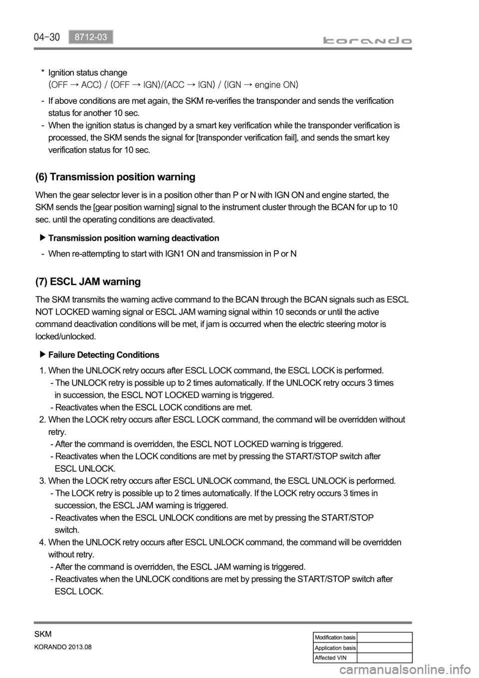
Ignition status change*
If above conditions are met again, the SKM re-verifies the transponder and sends the verification
status for another 10 sec.
When the ignition status is changed by a smart key verification while the transponder verification is
processed, the SKM sends the signal for [transponder verification fail], and sends the smart key
verification status for 10 sec. -
-
(6) Transmission position warning
When the gear selector lever is in a position other than P or N with IGN ON and engine started, the
SKM sends the [gear position warning] signal to the instrument cluster through the BCAN for up to 10
sec. until the operating conditions are deactivated.
Transmission position warning deactivation
When re-attempting to start with IGN1 ON and transmission in P or N -
(7) ESCL JAM warning
The SKM transmits the warning active command to the BCAN through the BCAN signals such as ESCL
NOT LOCKED warning signal or ESCL JAM warning signal within 10 seconds or until the active
command deactivation conditions will be met, if jam is occurred when the electric steering motor is
locked/unlocked.
Failure Detecting Conditions
When the UNLOCK retry occurs after ESCL LOCK command, the ESCL LOCK is performed.
- The UNLOCK retry is possible up to 2 times automatically. If the UNLOCK retry occurs 3 times
in succession, the ESCL NOT LOCKED warning is triggered.
- Reactivates when the ESCL LOCK conditions are met.
When the LOCK retry occurs after ESCL LOCK command, the command will be overridden without
retry.
- After the command is overridden, the ESCL NOT LOCKED warning is triggered.
- Reactivates when the LOCK conditions are met by pressing the START/STOP switch after
ESCL UNLOCK.
When the LOCK retry occurs after ESCL UNLOCK command, the ESCL UNLOCK is performed.
- The LOCK retry is possible up to 2 times automatically. If the LOCK retry occurs 3 times in
succession, the ESCL JAM warning is triggered.
- Reactivates when the ESCL UNLOCK conditions are met by pressing the START/STOP
switch.
When the UNLOCK retry occurs after ESCL UNLOCK command, the command will be overridden
without retry.
- After the command is overridden, the ESCL JAM warning is triggered.
- Reactivates when the UNLOCK conditions are met by pressing the START/STOP switch after
ESCL LOCK. 1.
2.
3.
4.
Page 783 of 1336

8712-03
(9) SKM error alert
The SKM sends the SKM error alert signal to the instrument cluster through the B-CAN for up to 10
sec. when an in ignition status related error or passive entry system error occurs.
SKM error transmission conditions
When any of the following errors is detected and a DTC is set, the SKM sends the error alert signal for
10 sec.
B+ (power) low voltage
B+ (logic) low voltage
ACC ON fail
ACC OFF fail
IGN1 ON fail
IGN1 OFF fail
IGN2 ON fail
IGN2 OFF fail
START/STOP switch short circuit 1.
2.
3.
4.
5.
6.
7.
8.
9.ESCL JAM Warning Deactivation
met again by pressing the START/STOP switch to change the ignition status within 10 seconds or after
10 seconds triggering the warning.
(8) ESCL FAIL warning
The SKM monitors the ESCL and transmits the warning active command to the BCAN for 10 seconds
Failure Transmitting Conditions
ESCL bolt status failure
ESCL no response error
- No response or incorrect response from ESCL 3 times in succession
Status mismatch
- Mismatch between ESCL bolt status and micro switch status
ESCL anti-scanning error
- Verification fails 2 times in succession 1.
2.
3.
4.
Page 784 of 1336

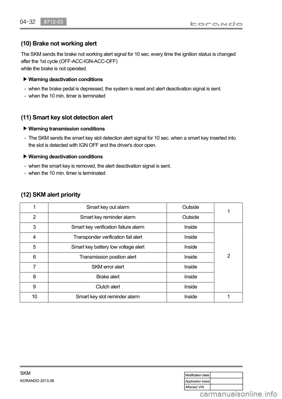
(10) Brake not working alert
The SKM sends the brake not working alert signal for 10 sec. every time the ignition status is changed
after the 1st cycle (OFF-ACC-IGN-ACC-OFF)
while the brake is not operated.
when the brake pedal is depressed, the system is reset and alert deactivation signal is sent.
when the 10 min. timer is terminated -
-
(11) Smart key slot detection alert
The SKM sends the smart key slot detection alert signal for 10 sec. when a smart key inserted into
the slot is detected with IGN OFF and the driver's door open. -
(12) SKM alert priority
1 Smart key out alarm Outside
1
2 Smart key reminder alarm Outside
3 Smart key verification failure alarm Inside
2 4 Transponder verification fail alert Inside
5 Smart key battery low voltage alert Inside
6 Transmission position alert Inside
7 SKM error alert Inside
8 Brake alert Inside
9 Clutch alert Inside
10 Smart key slot reminder alarm Inside 1
Warning deactivation conditions
Warning transmission conditions
Warning deactivation conditions
when the smart key is removed, the alert deactivation signal is sent.
when the 10 min. timer is terminated -
-
Page 785 of 1336

8712-03
Start motor
12. SKM IMMOBILIZER SYSTEM
1) System Description
The immobilizer system prevents the vehicle theft by allowing only the authorized key to start the engine.
The transponder inside the key communicates with the SKM (immobilizer slot) and EMS (ECU) through
P-CAN communication, and the system permits the engine to start after confirming the encrypted
coding.
When the START/STOP switch is pressed with the smart key inserted into the immobilizer slot because
of the smart key battery discharge, the SKM communicates with the EMS (ECU) through P-CAN, and
the ECU starts to control the engine only the signal is valid.
A valid key verification time is provided for 10 seconds and the engine can be started during this time. If
pressing the START/STOP switch again after this 10 seconds, the key verification process is performed
again.
2) Configuration
Emergency slot
Smart key
SKM
EMS (ECU)
Page 786 of 1336

3) Operating Process
Key verification can be divided into two types, immobilizer key verification and smart key verification. The
immobilizer verification is applied for the SKM system, and verifies the transponder built in the smart key.
When the smart key is inserted into the slot, the verification is carried out, overriding the RF signal from
the smart key.
The power is supplied to the slot when the START/STOP switch is pressed with the smart key inserted
into the slot, and the smart key transponder verification is carried out by the transponder communication.
Once the key is verified, a valid key verification time is provided for 10 seconds and the engine can be
started by pressing the START/STOP switch during this time. If pressing the START/STOP switch after
this 10 seconds, the key verification process is performed again.
When the ignition is turned ON, the EMS (ECU) sends the challenge message to the SKM through
the P-CAN. (This is to verify whether the transponder of the smart key is valid. If the verification fails,
it transmits the re-verification signals 3 times for 2 seconds. If 3rd re-verification fails, the verification
is deactivated for 10 seconds and re-activated after that.)
The immobilizer slot of the SKM system sends the encrypted cod to the transponder, and the
transponder re-sends the encrypted code to the immobilizer slot.
The encrypted sent to the immobilizer slot is re-sent to the SKM.
The SKM compares this code with the encrypted code randomly transmitted by the internal logic.
(System compares the signal from transponder and encrypted signal from the immobilizer control
unit)
Only when the two signals are identical, it recognizes the key as the verified one and transmits the
positive message to the ECU.
The ECU enables the engine to be started. 1.
2.
3.
4.
5.
6.
Page 787 of 1336

8010-01
1. SPECIFICATION
Pin No. Specification
Rated voltage DC 12.0 V
Operating voltage DC 9 V ~ 16 V
CAN operating
voltage DC 7 V ~ 18 V
Inspection voltage DC 13.5 V
Operating
temperature
Storage temperature
Dark currentIGN OFF: 1 mA, 12 Vturned off and stabilized data get
IGN ON: Max. 2 A, 12 V
Page 788 of 1336

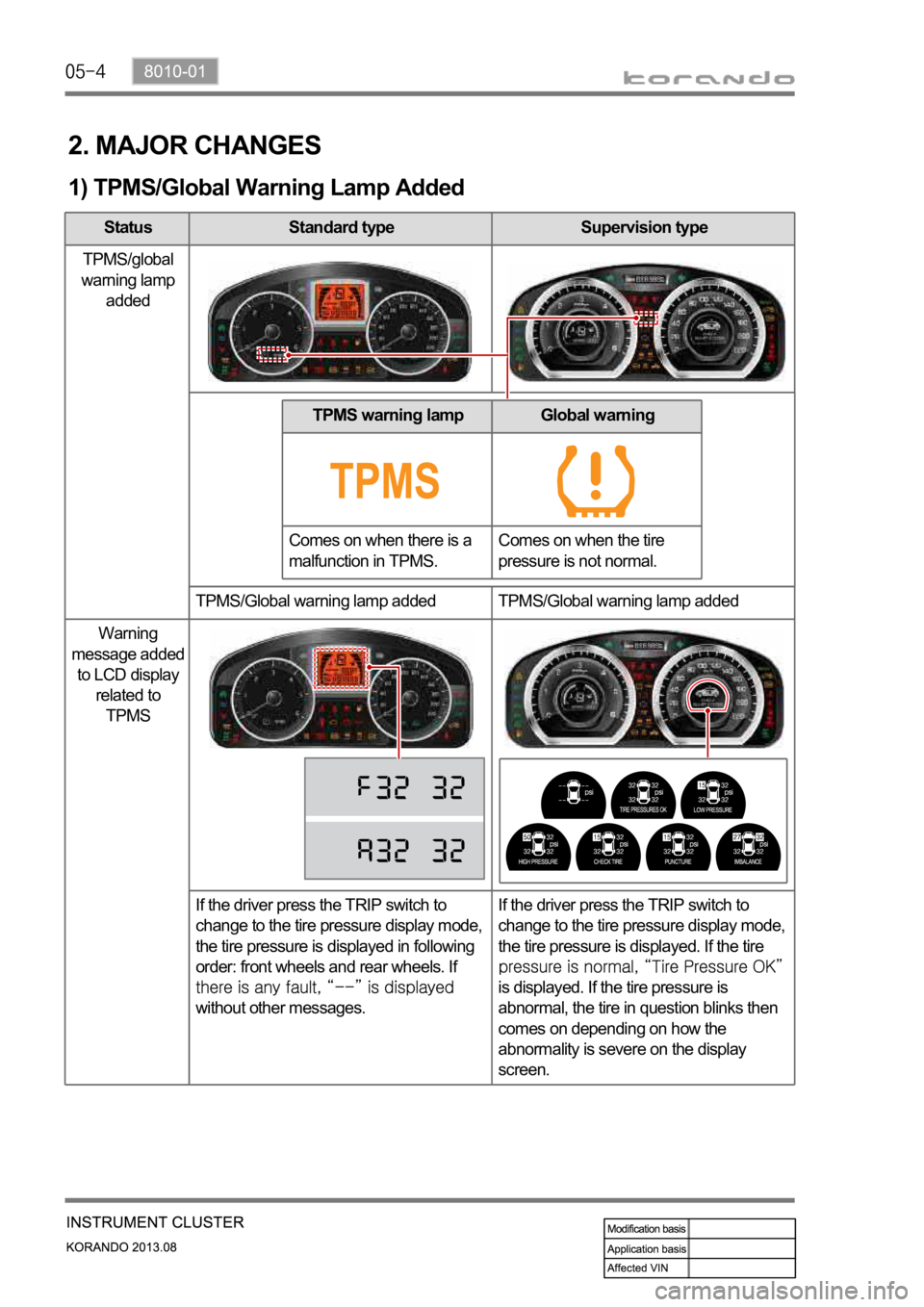
Status Standard type Supervision type
TPMS/global
warning lamp
added
TPMS/Global warning lamp added TPMS/Global warning lamp added
Warning
message added
to LCD display
related to
TPMS
If the driver press the TRIP switch to
change to the tire pressure display mode,
the tire pressure is displayed in following
order: front wheels and rear wheels. If
without other messages.If the driver press the TRIP switch to
change to the tire pressure display mode,
the tire pressure is displayed. If the tire
is displayed. If the tire pressure is
abnormal, the tire in question blinks then
comes on depending on how the
abnormality is severe on the display
screen.
2. MAJOR CHANGES
1) TPMS/Global Warning Lamp Added
TPMS warning lamp
Comes on when there is a
malfunction in TPMS.Global warning
Comes on when the tire
pressure is not normal.
Page 789 of 1336

8010-01
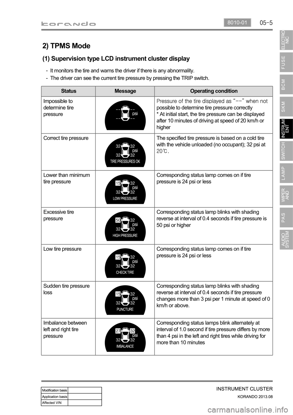
2) TPMS Mode
(1) Supervision type LCD instrument cluster display
It monitors the tire and warns the driver if there is any abnormality.
The driver can see the current tire pressure by pressing the TRIP switch. -
-
Status Message Operating condition
Impossible to
determine tire
pressure
possible to determine tire pressure correctly
* At initial start, the tire pressure can be displayed
after 10 minutes of driving at speed of 20 km/h or
higher
Correct tire pressure The specified tire pressure is based on a cold tire
with the vehicle unloaded (no occupant); 32 psi at
Lower than minimum
tire pressureCorresponding status lamp comes on if tire
pressure is 24 psi or less
Excessive tire
pressureCorresponding status lamp blinks with shading
reverse at interval of 0.4 seconds if tire pressure is
50 psi or higher
Low tire pressure Corresponding status lamp comes on if tire
pressure is 24 psi or less
Sudden tire pressure
lossCorresponding status lamp blinks with shading
reverse at interval of 0.4 seconds if tire pressure
changes more than 3 psi per 1 minute at speed of 0
km/h or above.
Imbalance between
left and right tire
pressureCorresponding status lamps blink alternately at
interval of 1.0 second if tire pressure differs by more
than 4 psi in the left and right tires while driving for
more than 10 minutes
Page 790 of 1336

(2) Standard type LCD instrument cluster display
-
3) GSI(Gear Shift Indication)
Status Standard type Supervision type
Display gear
stage for
manual
transmission
Informs appropriate shift time for manual transmission
: This means that you should shift up to 3rd gear.
(2nd gear or lower currently)
: This means that you should shift down to 3rd gear.
(4th gear or higher currently)
The system operates normally when the indicator lamp looks not being gone out
completely.