SUBARU FORESTER 2004 Service Repair Manual
Manufacturer: SUBARU, Model Year: 2004, Model line: FORESTER, Model: SUBARU FORESTER 2004Pages: 2870, PDF Size: 38.67 MB
Page 1161 of 2870

EN(H4SO)-63
ENGINE (DIAGNOSTIC)
Diagnostics for Engine Starting Failure
8 CHECK GROUND CIRCUIT OF MAIN RE-
LAY.
1) Turn the ignition switch to OFF.
2) Measure the resistance between main relay
connector and chassis ground.
Connector & terminal
(B47) No. 1 — Chassis ground:Is the resistance less than 5
Ω?Go to step 9.Repair open circuit
between main
relay and chassis
ground.
9 CHECK INPUT VOLTAGE OF MAIN RELAY.
Measure the voltage between main relay con-
nector and chassis ground.
Connector & terminal
(B47) No. 5 (+) — Chassis ground (
−):
(B47) No. 6 (+) — Chassis ground (
−):Is the voltage more than 10 V? Go to step 10.Repair open or
ground short cir-
cuit in harness of
power supply cir-
cuit.
10 CHECK INPUT VOLTAGE OF ECM.
1) Connect the main relay connector.
2) Turn the ignition switch to ON.
3) Measure the voltage between ECM con-
nector and chassis ground.
Connector & terminal
(B135) No. 1 (+) — Chassis ground (
−):
(B135) No. 2 (+) — Chassis ground (
−):
(B136) No. 23 (+) — Chassis ground (
−):Is the voltage more than 10 V? Check ignition
control system.
IGNITION CON-
TROL SYSTEM,
Diagnostics for
Engine Starting
Fa il u r e. >Repair open or
ground short cir-
cuit in harness
between ECM
connector and
main relay connec-
tor. Step Check Yes No
Page 1162 of 2870

EN(H4SO)-64
ENGINE (DIAGNOSTIC)
Diagnostics for Engine Starting Failure
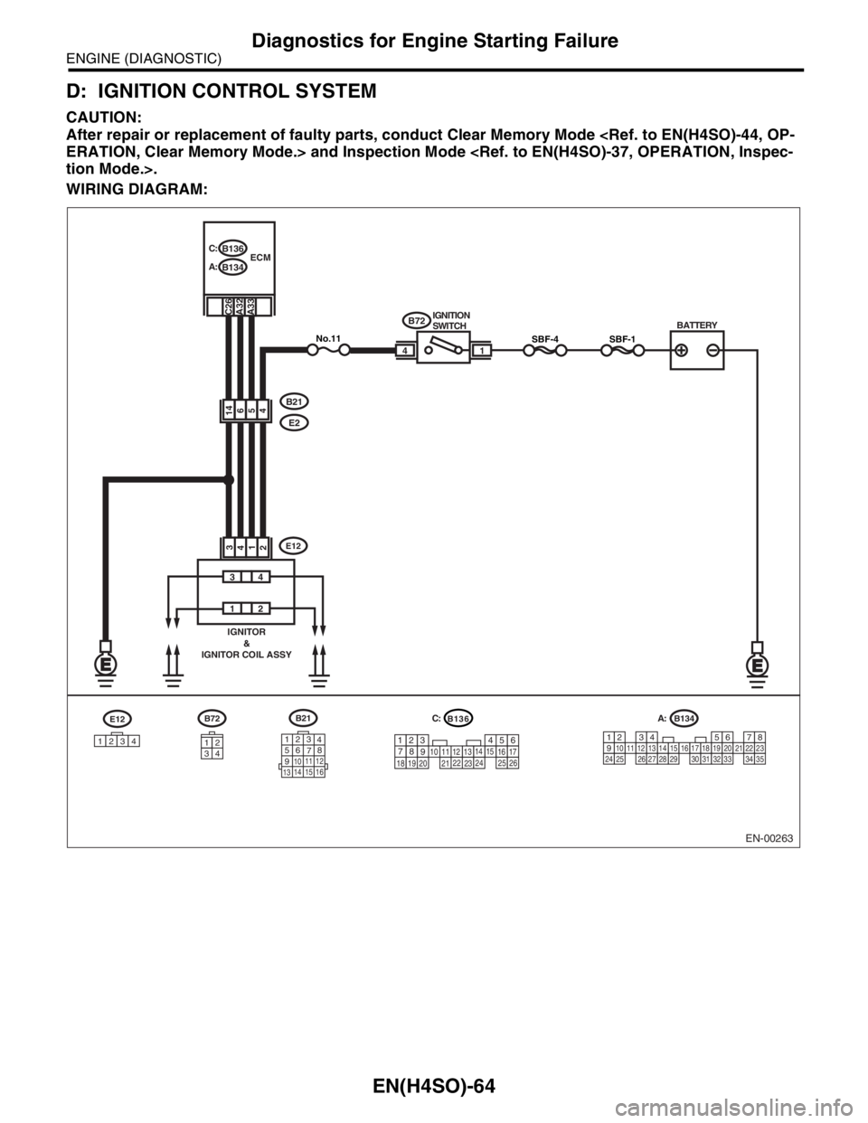
D: IGNITION CONTROL SYSTEM
CAUTION:
After repair or replacement of faulty parts, conduct Clear Memory Mode
WIRING DIAGRAM:
EN-00263
BATTERY
1 IGNITION
SWITCHSBF-44
A32
B21
E2
B134
1234567891011121314151617181920212223242526272829303132333435
B72
34
12
SBF-1No.11
54146
1234
B136 C:
B134 A:ECM
A33C26
34
12
IGNITOR
&
IGNITOR COIL ASSY
1234
E12B21
123
4
56
78
9
1011 12
1314 15 16
B72
B136
5
2
84
3923 20 211011
221617
24
2512136
261915
14
1
7
18
E12
C:
A:
Page 1163 of 2870

EN(H4SO)-65
ENGINE (DIAGNOSTIC)
Diagnostics for Engine Starting Failure
Step Check Yes No
1 CHECK IGNITION SYSTEM FOR SPARKS.
1) Remove the plug cord cap from each spark
plug.
2) Install the new spark plug on plug cord cap.
CAUTION:
Do not remove the spark plug from engine.
3) Contact the spark plug’s thread portion on
engine.
4) While opening the throttle valve fully, crank
the engine to check that spark occurs at each
cylinder.Does spark occur at each cyl-
inder?Check fuel pump
system.
FUEL PUMP CIR-
CUIT, Diagnostics
for Engine Start-
ing Failure.>Go to step 2.
2 CHECK POWER SUPPLY CIRCUIT FOR IG-
NITION COIL & IGNITOR ASSY.
1) Turn the ignition switch to OFF.
2) Disconnect the connector from ignition coil
& ignitor ASSY.
3) Turn the ignition switch to ON.
4) Measure the power supply voltage between
ignition coil & ignitor ASSY connector and
engine ground.
Connector & terminal
(E12) No. 2 (+) — Engine ground (
−):Is the voltage more than 10 V? Go to step 3.Repair harness
and connector.
N
OTE:
In this case repair
the following:
Open circuit in
harness between
ignition coil & igni-
tor ASSY, and
main relay connec-
tor
Poor contact in
coupling connector
Blown out fuse
3 CHECK HARNESS OF IGNITION COIL & IG-
NITOR ASSY GROUND CIRCUIT.
1) Turn the ignition switch to OFF.
2) Measure the resistance between ignition
coil & ignitor ASSY connector and engine
ground.
Connector & terminal
(E12) No. 3 — Engine ground:Is the resistance less than 5
Ω?Go to step 4.Repair harness
and connector.
N
OTE:
In this case repair
the following:
Open circuit in
harness between
ignition coil & igni-
tor ASSY connec-
tor and engine
ground terminal
4 CHECK IGNITION COIL & IGNITOR ASSY.
1) Remove the spark plug cords.
2) Measure the resistance between spark
plug cord contact portions to check secondary
coil.
Te r m i n a l s
No. 1 — No. 2:
No. 3 — No. 4:Is the resistance 10 — 15 kΩ? Go to step 5.Replace the igni-
tion coil & ignitor
ASSY.
tion Coil & Ignitor
Assembly.>
5 CHECK INPUT SIGNAL FOR IGNITION COIL
& IGNITOR ASSY.
1) Connect the connector to ignition coil &
ignitor ASSY.
2) Check if voltage varies synchronously with
engine speed when cranking, while monitoring
voltage between ignition coil & ignitor ASSY
connector and engine ground.
Connector & terminal
(E12) No. 1 (+) — Engine ground (
−):
(E12) No. 4 (+) — Engine ground (
−):Does the voltage vary more
than 10 V?Go to step 6.Replace the igni-
tion coil & ignitor
ASSY.
tion Coil & Ignitor
Assembly.>
Page 1164 of 2870

EN(H4SO)-66
ENGINE (DIAGNOSTIC)
Diagnostics for Engine Starting Failure
6 CHECK HARNESS BETWEEN ECM AND IG-
NITION COIL & IGNITOR ASSY CONNEC-
TOR.
1) Turn the ignition switch to OFF.
2) Disconnect the connector from ECM.
3) Disconnect the connector from ignition coil
& ignitor ASSY.
4) Measure the resistance of harness
between ECM and ignition coil & ignitor ASSY
connector.
Connector & terminal
(B134) No. 32 — (E12) No. 1:
(B134) No. 32 — (E12) No. 4:Is the resistance less than 1
Ω?Go to step 7.Repair harness
and connector.
N
OTE:
In this case repair
the following:
Open circuit in
harness between
ECM and ignition
coil & ignitor ASSY
connector.
Poor contact in
coupling connector
7 CHECK HARNESS BETWEEN ECM AND IG-
NITION COIL & IGNITOR ASSY CONNEC-
TOR.
Measure the resistance of harness between
ECM and engine ground.
Connector & terminal:
(B134) No. 32 — Engine ground:Is the resistance more than 1
MΩ?Go to step 8.Repair ground
short circuit in har-
ness between
ECM and ignition
coil & ignitor ASSY
connector.
8 CHECK POOR CONTACT.
Check poor contact in ECM connector. Is there poor contact in ECM
connector?Repair the poor
contact in ECM
connector.Check fuel pump
circuit.
FUEL PUMP CIR-
CUIT, Diagnostics
for Engine Start-
ing Failure.> Step Check Yes No
Page 1165 of 2870

EN(H4SO)-67
ENGINE (DIAGNOSTIC)
Diagnostics for Engine Starting Failure
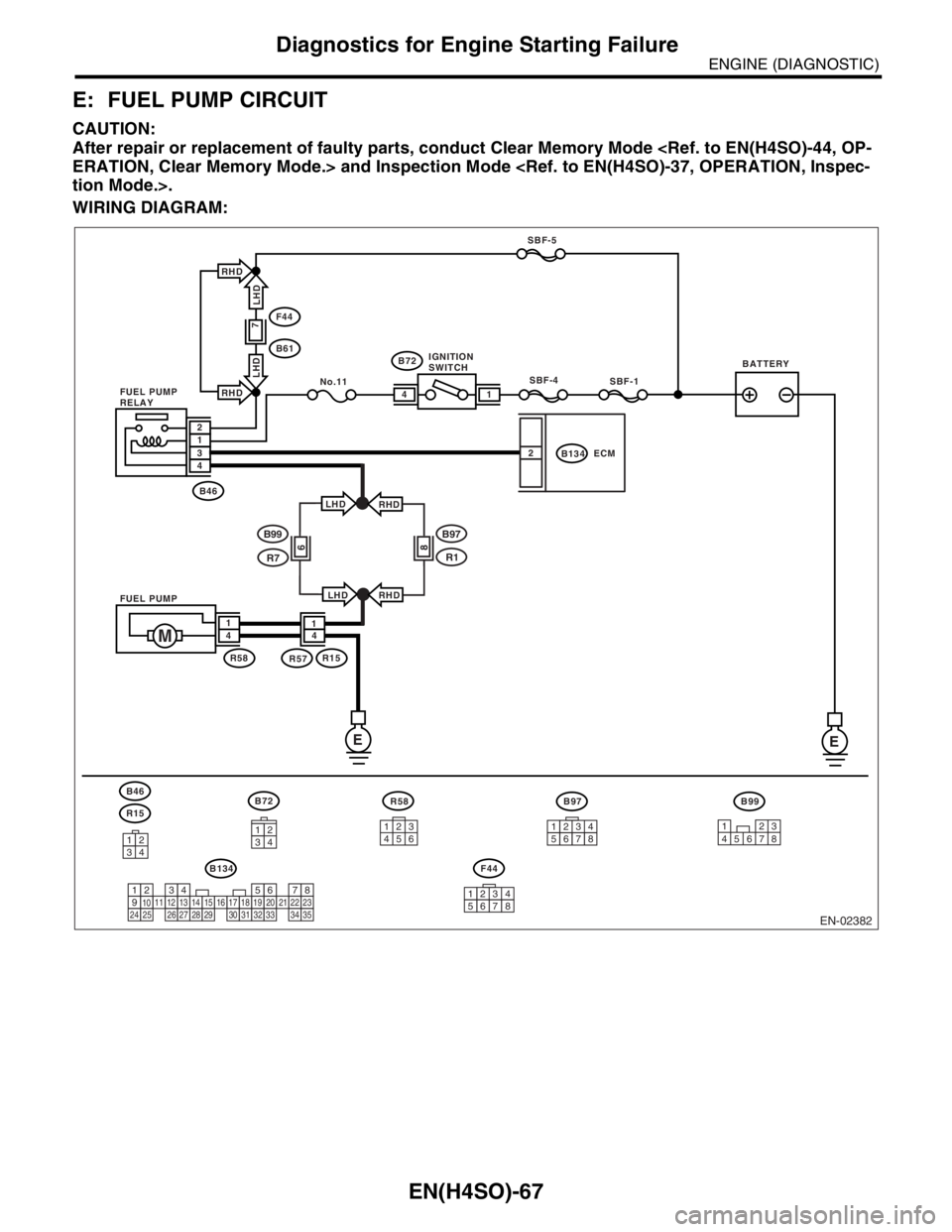
E: FUEL PUMP CIRCUIT
CAUTION:
After repair or replacement of faulty parts, conduct Clear Memory Mode
WIRING DIAGRAM:
EN-02382
B72B46
R15
F44
B99
B134
R58
3412
SBF-1
No.11SBF-4
E
1
2 4
B72
F44
B61
B46
R58R57R15
SBF-5
2134
4M14 1
B134ECM
341213
4562
12345678
1234567891011121314151617181920212223242526272829303132333435
BATTERY IGNITION
SWITCH
FUEL PUMP
RELAY
FUEL PUMP
7
B99
R7
B97
R186
LHD
LHDRHD
RHD
B97
12345678
RHD
LHD
LHD
RHD
E
123
45678
Page 1166 of 2870

EN(H4SO)-68
ENGINE (DIAGNOSTIC)
Diagnostics for Engine Starting Failure
Step Check Yes No
1 CHECK OPERATING SOUND OF FUEL
PUMP.
Check that the fuel pump is in operation for two
seconds when turning the ignition switch to
ON.
N
OTE:
Fuel pump operation can also be executed us-
ing Subaru Select Monitor.
Refer to “Compulsory Valve Operation Check
Mode” for procedures.
operating sound?Check the fuel
injector circuit.
FUEL INJECTOR
CIRCUIT, Diag-
nostics for Engine
Starting Failure.>Go to step 2.
2 CHECK GROUND CIRCUIT OF FUEL PUMP.
1) Turn the ignition switch to OFF.
2) Remove the fuel pump access hole lid.
3) Disconnect the connector from fuel pump.
4) Measure the resistance of harness connec-
tor between fuel pump and chassis ground.
Connector & terminal
(R58) No. 4 — Chassis ground:Is the resistance less than 5
Ω?Go to step 3.Repair harness
and connector.
N
OTE:
In this case repair
the following:
Open circuit in
harness between
fuel pump connec-
tor and chassis
grounding terminal
Poor contact in
coupling connector
3 CHECK POWER SUPPLY TO FUEL PUMP.
1) Turn the ignition switch to ON.
2) Measure the voltage of power supply circuit
between fuel pump connector and chassis
ground.
Connector & terminal
(R58) No. 1 (+) — Chassis ground (
−):Is the voltage more than 10 V? Replace the fuel
pump.
Fuel Pump.>Go to step 4.
4 CHECK HARNESS BETWEEN FUEL PUMP
AND FUEL PUMP RELAY CONNECTOR.
1) Turn the ignition switch to OFF.
2) Measure the resistance of harness connec-
tor between fuel pump and fuel pump relay.
Connector & terminal
(R58) No. 1 — (B46) No. 4:Is the resistance less than 1
Ω?Go to step 5.Repair harness
and connector.
N
OTE:
In this case repair
the following:
Open circuit in
harness between
fuel pump connec-
tor and chassis
grounding terminal
Poor contact in
coupling connector
5 CHECK HARNESS BETWEEN FUEL PUMP
AND FUEL PUMP RELAY CONNECTOR.
Measure the resistance of harness between
fuel pump and fuel pump relay connector.
Connector & terminal
(R58) No. 1 — Chassis ground:Is the resistance more than 1
MΩ?Go to step 6.Repair short circuit
in harness
between fuel pump
and fuel pump
relay connector.
6 CHECK FUEL PUMP RELAY.
1) Disconnect the connectors from fuel pump
relay and main relay.
2) Remove the fuel pump relay and main relay
with bracket.
3) Connect the battery to fuel pump relay con-
nector terminals No. 1 and No. 3.
4) Measure the resistance between connector
terminals of fuel pump relay.
Te r m i n a l s
No. 2 — No. 4:Is the resistance less than 10
Ω?Go to step 7.Replace the fuel
pump relay.
Fuel Pump.>
Page 1167 of 2870

EN(H4SO)-69
ENGINE (DIAGNOSTIC)
Diagnostics for Engine Starting Failure
7 CHECK HARNESS BETWEEN ECM AND
FUEL PUMP RELAY CONNECTOR.
1) Disconnect the connector from ECM.
2) Measure the resistance of harness
between ECM and fuel pump relay connector.
Connector & terminal
(B134) No. 26 — (B46) No. 3:Is the resistance less than 1
Ω?Go to step 8.Repair open circuit
in harness
between ECM and
fuel pump relay
connector.
8 CHECK POOR CONTACT.
Check poor contact in ECM connector.Is there poor contact in ECM
connector?Repair the poor
contact in ECM
connector.Check the fuel
injector circuit.
FUEL INJECTOR
CIRCUIT, Diag-
nostics for Engine
Starting Failure.> Step Check Yes No
Page 1168 of 2870

EN(H4SO)-70
ENGINE (DIAGNOSTIC)
Diagnostics for Engine Starting Failure
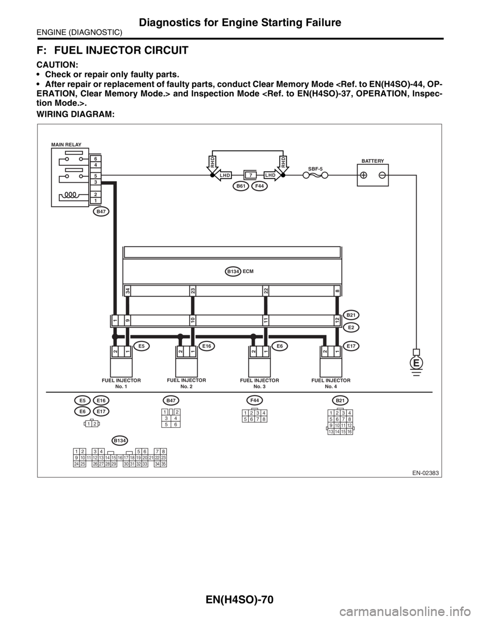
F: FUEL INJECTOR CIRCUIT
CAUTION:
Check or repair only faulty parts.
After repair or replacement of faulty parts, conduct Clear Memory Mode
WIRING DIAGRAM:
EN-02383
B21
12345678910111213141516
E6E17
E5E16
12
12121212
2223348
91101112
ECM
B134
E5E16E6E17
B21
E2
FUEL INJECTOR
No. 1FUEL INJECTOR
No. 2FUEL INJECTOR
No. 3FUEL INJECTOR
No. 4
BATTERY
F44B61
SBF-5
B47 MAIN RELAY
12
35
46
B47
34
12
56
F44
12345678
B134
1234567891011121314151617181920212223242526272829303132333435
LHDLHD
RHDRHD
7
Page 1169 of 2870

EN(H4SO)-71
ENGINE (DIAGNOSTIC)
Diagnostics for Engine Starting Failure
Step Check Yes No
1 CHECK OPERATION OF EACH FUEL INJEC-
TOR.
While cranking the engine, check that each
fuel injector emits operating sound. Use a
sound scope or apply a screwdriver to the
injector for this check.Does the fuel pump emit oper-
ating sound?Check the fuel
pressure.
INSPECTION,
Fuel Pressure.>Go to step 2.
2 CHECK POWER SUPPLY TO EACH FUEL
INJECTOR.
1) Turn the ignition switch to OFF.
2) Disconnect the connector from fuel injector.
3) Turn the ignition switch to ON.
4) Measure the power supply voltage between
fuel injector terminal and engine ground.
Connector & terminal
#1 (E5) No. 2 (+) — Engine ground (
−):
#2 (E16) No. 2 (+) — Engine ground (
−):
#3 (E6) No. 2 (+) — Engine ground (
−):
#4 (E17) No. 2 (+) — Engine ground (
−):Is the voltage more than 10 V? Go to step 3.Repair harness
and connector.
N
OTE:
In this case repair
the following:
Open circuit in
harness between
main relay and fuel
injector connector
Poor contact in
main relay connec-
tor
Poor contact in
coupling connector
Poor contact in
fuel injector con-
nector
3 CHECK HARNESS BETWEEN ECM AND
FUEL INJECTOR CONNECTOR.
1) Disconnect the connector from ECM.
2) Measure the resistance of harness
between ECM and fuel injector connector.
Connector & terminal
#1 (B134) No. 34 — (E5) No. 1:
#2 (B134) No. 23 — (E16) No. 1:
#3 (B134) No. 22 — (E6) No. 1:
#4 (B134) No. 8 — (E17) No. 1:Is the resistance less than 1
Ω?Go to step 4.Repair harness
and connector.
N
OTE:
In this case repair
the following:
Open circuit in
harness between
ECM and fuel
injector connector
Poor contact in
coupling connector
4 CHECK HARNESS BETWEEN ECM AND
FUEL INJECTOR CONNECTOR.
Measure the resistance of harness between
ECM and fuel injector connector.
Connector & terminal
#1 (B134) No. 34 — Chassis ground:
#2 (B134) No. 23 — Chassis ground:
#3 (B134) No. 22 — Chassis ground:
#4 (B134) No. 8 — Chassis ground:Is the resistance more than 1
MΩ?Go to step 5.Repair ground
short circuit in har-
ness between
ECM and fuel
injector connector.
5 CHECK EACH FUEL INJECTOR.
1) Turn the ignition switch to OFF.
2) Measure the resistance between each fuel
injector terminals.
Te r m i n a l s
No. 1 — No. 2:Is the resistance 5 — 20 Ω? Go to step 6.Replace the faulty
fuel injector.
6 CHECK POOR CONTACT.
Check poor contact in ECM connector.Is there poor contact in ECM
connector?Repair the poor
contact in ECM
connector.Inspection using
“General Diagnos-
tic Table”
INSPECTION,
General Diagnos-
tic Table.>
Page 1170 of 2870

EN(H4SO)-72
ENGINE (DIAGNOSTIC)
List of Diagnostic Trouble Code (DTC)
18.List of Diagnostic Trouble Code (DTC)
A: LIST
DTC Item NOTE
P0030 HO2S Heater Control Circuit (Bank 1
Sensor 1)
(DTC).>
P0031 HO2S Heater Control Circuit Low
(Bank 1 Sensor 1)
Code (DTC).>
P0032 HO2S Heater Control Circuit High
(Bank 1 Sensor 1)
Code (DTC).>
P0037 HO2S Heater Control Circuit Low
(Bank 1 Sensor 2)
Code (DTC).>
P0038 HO2S Heater Control Circuit High
(Bank 1 Sensor 2)
Code (DTC).>
P0068 Manifold Pressure Sensor Range/
Pe r fo r ma nc e
Code (DTC).>
P0107 Manifold Absolute Pressure/Baro-
metric Pressure Circuit Low Input
with Diagnostic Trouble Code (DTC).>
P0108 Manifold Absolute Pressure/Baro-
metric Pressure Circuit High Input
with Diagnostic Trouble Code (DTC).>
P0111 Intake Air Temperature Circuit
Range/Performance
Code (DTC).>
P0112 Intake Air Temperature Circuit Low
Input
(DTC).>
P0113 Intake Air Temperature Circuit High
Input
(DTC).>
P0117 Engine Coolant Temperature Circuit
Low Input
(DTC).>
P0118 Engine Coolant Temperature Circuit
High Input
(DTC).>
P0121 Throttle/Pedal Position Sensor/
Switch “A” Circuit Range/Perfor-
mance
dure with Diagnostic Trouble Code (DTC).>
P0122 Throttle/Pedal Position Sensor/
Switch “A” Circuit Low Input
nostic Trouble Code (DTC).>
P0123 Throttle/Pedal Position Sensor/
Switch “A” Circuit High Input
nostic Trouble Code (DTC).>
P0125 Insufficient Coolant Temperature For
Closed Loop Fuel Control
Diagnostic Trouble Code (DTC).>
P0129 Barometric Pressure Too Low