SUBARU FORESTER 2004 Service Repair Manual
Manufacturer: SUBARU, Model Year: 2004, Model line: FORESTER, Model: SUBARU FORESTER 2004Pages: 2870, PDF Size: 38.67 MB
Page 1491 of 2870
ME(H4DOTC)-35
MECHANICAL
Engine Oil Pressure
6. Engine Oil Pressure
A: INSPECTION
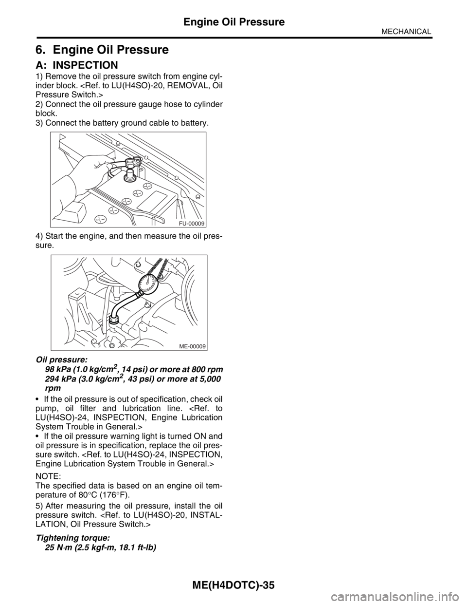
1) Remove the oil pressure switch from engine cyl-
inder block.
2) Connect the oil pressure gauge hose to cylinder
block.
3) Connect the battery ground cable to battery.
4) Start the engine, and then measure the oil pres-
sure.
Oil pressure:
98 kPa (1.0 kg/cm
2, 14 psi) or more at 800 rpm
294 kPa (3.0 kg/cm2, 43 psi) or more at 5,000
rpm
If the oil pressure is out of specification, check oil
pump, oil filter and lubrication line.
System Trouble in General.>
If the oil pressure warning light is turned ON and
oil pressure is in specification, replace the oil pres-
sure switch.
NOTE:
The specified data is based on an engine oil tem-
perature of 80°C (176°F).
5) After measuring the oil pressure, install the oil
pressure switch.
Tightening torque:
25 N
⋅m (2.5 kgf-m, 18.1 ft-lb)
FU-00009
ME-00009
Page 1492 of 2870
ME(H4DOTC)-36
MECHANICAL
Fuel Pressure
7. Fuel Pressure
A: INSPECTION
CAUTION:
Before removing the fuel pressure gauge, re-
lease the fuel pressure.
NOTE:
If out of specification, check or replace the pressure
regulator and pressure regulator vacuum hose.
1) Release the fuel pressure.
SURE, OPERATION, Fuel.>
2) Open the fuel filler flap lid, and then remove the
fuel filler cap.
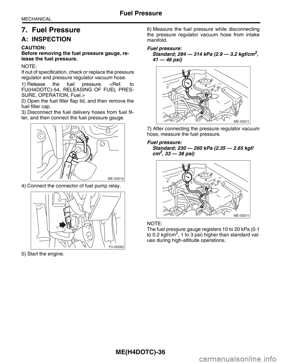
3) Disconnect the fuel delivery hoses from fuel fil-
ter, and then connect the fuel pressure gauge.
4) Connect the connector of fuel pump relay.
5) Start the engine.6) Measure the fuel pressure while disconnecting
the pressure regulator vacuum hose from intake
manifold.
Fuel pressure:
Standard; 284 — 314 kPa (2.9 — 3.2 kgf/cm2,
41 — 46 psi)
7) After connecting the pressure regulator vacuum
hose, measure the fuel pressure.
Fuel pressure:
Standard; 230 — 260 kPa (2.35 — 2.65 kgf/
cm
2, 33 — 38 psi)
NOTE:
The fuel pressure gauge registers 10 to 20 kPa (0.1
to 0.2 kgf/cm
2, 1 to 3 psi) higher than standard val-
ues during high-altitude operations.
ME-00010
FU-00262
ME-00011
ME-00011
Page 1493 of 2870
ME(H4DOTC)-37
MECHANICAL
Valve Clearance
8. Valve Clearance
A: INSPECTION
Inspection and adjustment of the valve clearance
should be performed while engine is cold.
1) Set the vehicle on a lift.
2) Disconnect the ground cable from battery.
3) Remove the air intake duct.
4) Remove the bolts which secure the timing belt
cover (RH).
5) Lift-up the vehicle.
6) Remove the under cover.
7) Loosen the remaining bolts which secure the
timing belt cover (RH), and then remove the timing
belt cover.
8) Lower the vehicle.
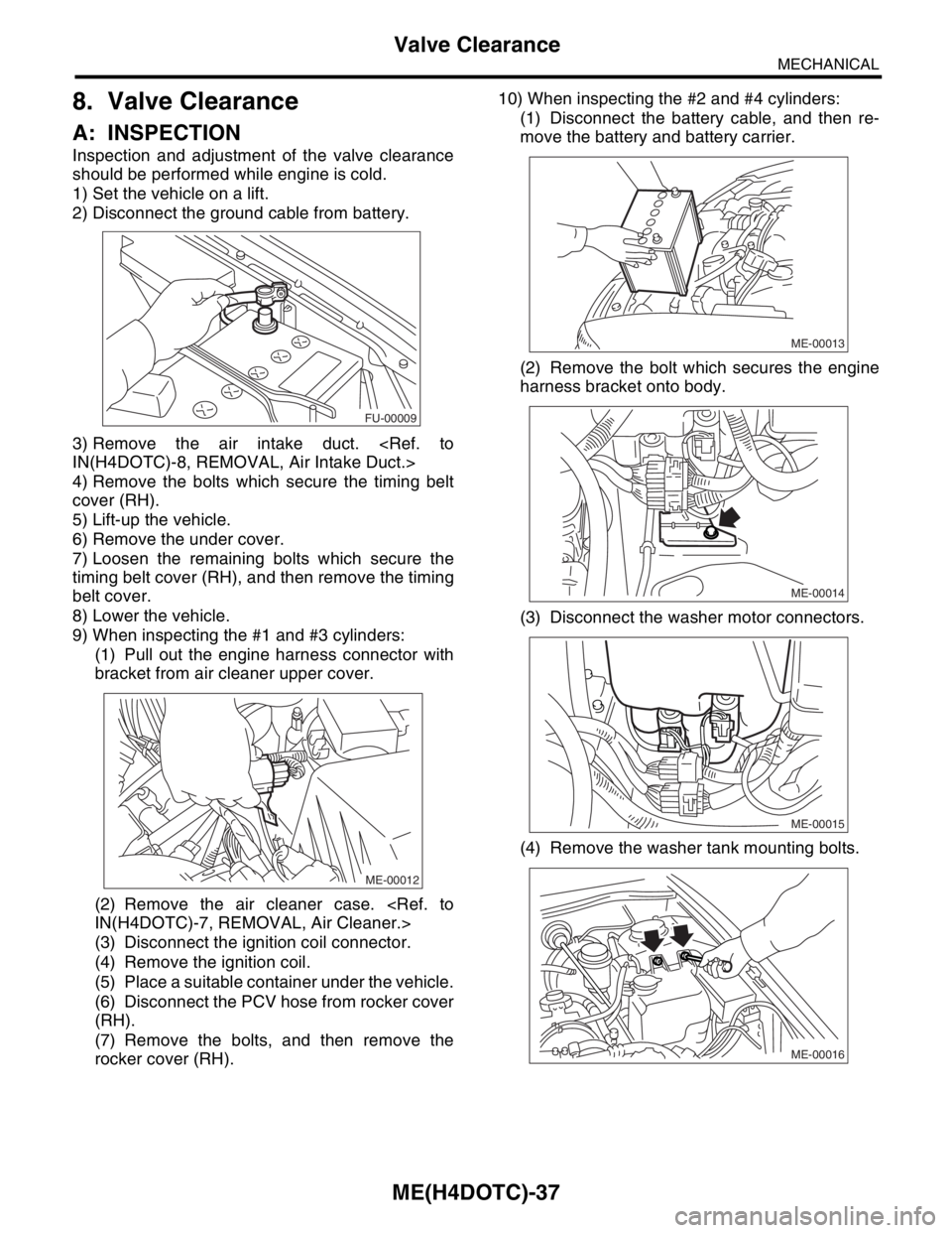
9) When inspecting the #1 and #3 cylinders:
(1) Pull out the engine harness connector with
bracket from air cleaner upper cover.
(2) Remove the air cleaner case.
(3) Disconnect the ignition coil connector.
(4) Remove the ignition coil.
(5) Place a suitable container under the vehicle.
(6) Disconnect the PCV hose from rocker cover
(RH).
(7) Remove the bolts, and then remove the
rocker cover (RH).10) When inspecting the #2 and #4 cylinders:
(1) Disconnect the battery cable, and then re-
move the battery and battery carrier.
(2) Remove the bolt which secures the engine
harness bracket onto body.
(3) Disconnect the washer motor connectors.
(4) Remove the washer tank mounting bolts.
FU-00009
ME-00012
ME-00013
ME-00014
ME-00015
ME-00016
Page 1494 of 2870
ME(H4DOTC)-38
MECHANICAL
Valve Clearance
(5) Move the washer tank upward.
(6) Disconnect the ignition coil connector.
(7) Remove the ignition coil.
(8) Place a suitable container under the vehicle.
(9) Disconnect the PCV hose from rocker cover
(LH).
(10)Remove the bolts, and then remove the
rocker cover (LH).
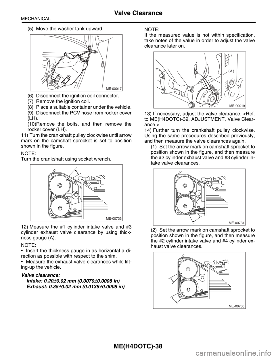
11) Turn the crankshaft pulley clockwise until arrow
mark on the camshaft sprocket is set to position
shown in the figure.
NOTE:
Turn the crankshaft using socket wrench.
12) Measure the #1 cylinder intake valve and #3
cylinder exhaust valve clearance by using thick-
ness gauge (A).
NOTE:
Insert the thickness gauge in as horizontal a di-
rection as possible with respect to the shim.
Measure the exhaust valve clearances while lift-
ing-up the vehicle.
Valve clearance:
Intake: 0.20
±0.02 mm (0.0079±0.0008 in)
Exhaust: 0.35
±0.02 mm (0.0138±0.0008 in)NOTE:
If the measured value is not within specification,
take notes of the value in order to adjust the valve
clearance later on.
13) If necessary, adjust the valve clearance.
ance.>
14) Further turn the crankshaft pulley clockwise.
Using the same procedures described previously,
and then measure the valve clearances again.
(1) Set the arrow mark on camshaft sprocket to
position shown in the figure, and then measure
the #2 cylinder exhaust valve and #3 cylinder in-
take valve clearances.
(2) Set the arrow mark on camshaft sprocket to
position shown in the figure, and then measure
the #2 cylinder intake valve and #4 cylinder ex-
haust valve clearances.
ME-00017
ME-00733
ME-00019
(A)
ME-00734
ME-00735
Page 1495 of 2870
ME(H4DOTC)-39
MECHANICAL
Valve Clearance
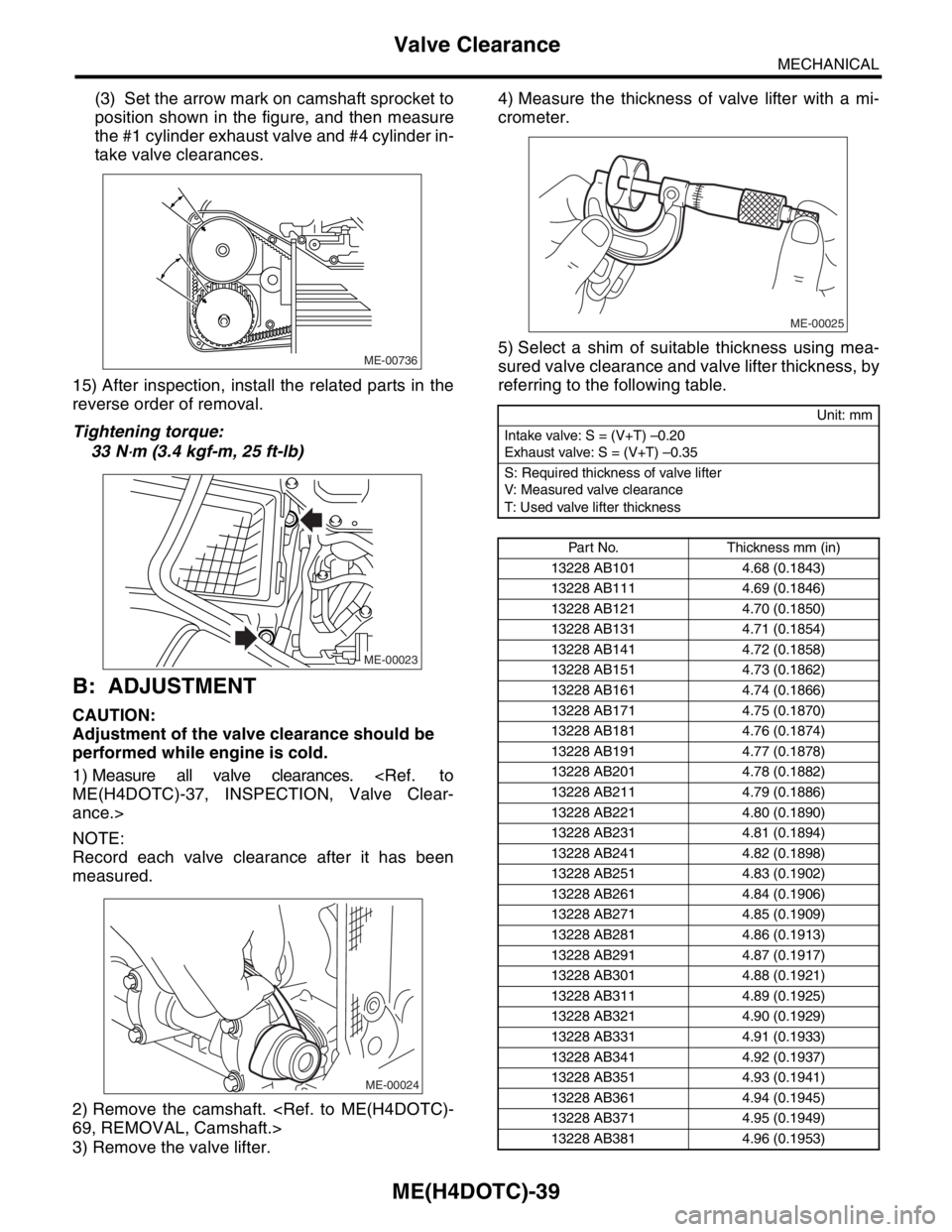
(3) Set the arrow mark on camshaft sprocket to
position shown in the figure, and then measure
the #1 cylinder exhaust valve and #4 cylinder in-
take valve clearances.
15) After inspection, install the related parts in the
reverse order of removal.
Tightening torque:
33 N
⋅m (3.4 kgf-m, 25 ft-lb)
B: ADJUSTMENT
CAUTION:
Adjustment of the valve clearance should be
performed while engine is cold.
1) Measure all valve clearances.
ance.>
NOTE:
Record each valve clearance after it has been
measured.
2) Remove the camshaft.
3) Remove the valve lifter.4) Measure the thickness of valve lifter with a mi-
crometer.
5) Select a shim of suitable thickness using mea-
sured valve clearance and valve lifter thickness, by
referring to the following table.
ME-00736
ME-00023
ME-00024
Unit: mm
Intake valve: S = (V+T) –0.20
Exhaust valve: S = (V+T) –0.35
S: Required thickness of valve lifter
V: Measured valve clearance
T: Used valve lifter thickness
Part No. Thickness mm (in)
13228 AB101 4.68 (0.1843)
13228 AB111 4.69 (0.1846)
13228 AB121 4.70 (0.1850)
13228 AB131 4.71 (0.1854)
13228 AB141 4.72 (0.1858)
13228 AB151 4.73 (0.1862)
13228 AB161 4.74 (0.1866)
13228 AB171 4.75 (0.1870)
13228 AB181 4.76 (0.1874)
13228 AB191 4.77 (0.1878)
13228 AB201 4.78 (0.1882)
13228 AB211 4.79 (0.1886)
13228 AB221 4.80 (0.1890)
13228 AB231 4.81 (0.1894)
13228 AB241 4.82 (0.1898)
13228 AB251 4.83 (0.1902)
13228 AB261 4.84 (0.1906)
13228 AB271 4.85 (0.1909)
13228 AB281 4.86 (0.1913)
13228 AB291 4.87 (0.1917)
13228 AB301 4.88 (0.1921)
13228 AB311 4.89 (0.1925)
13228 AB321 4.90 (0.1929)
13228 AB331 4.91 (0.1933)
13228 AB341 4.92 (0.1937)
13228 AB351 4.93 (0.1941)
13228 AB361 4.94 (0.1945)
13228 AB371 4.95 (0.1949)
13228 AB381 4.96 (0.1953)
ME-00025
Page 1496 of 2870

ME(H4DOTC)-40
MECHANICAL
Valve Clearance
6) Inspect all valves for clearance again at this
stage. If the valve clearance is not correct, repeat
the procedure over again from the first step.
7) After inspection, install the related parts in the
reverse order of removal.
13228 AB391 4.97 (0.1957)
13228 AB401 4.98 (0.1961)
13228 AB411 4.99 (0.1965)
13228 AB421 5.00 (0.1969)
13228 AB431 5.01 (0.1972)
13228 AB441 5.02 (0.1976)
13228 AB451 5.03 (0.1980)
13228 AB461 5.04 (0.1984)
13228 AB471 5.05 (0.1988)
13228 AB481 5.06 (0.1992)
13228 AB491 5.07 (0.1996)
13228 AB501 5.08 (0.2000)
13228 AB511 5.09 (0.2004)
13228 AB521 5.10 (0.2008)
13228 AB531 5.11 (0.2012)
13228 AB541 5.12 (0.2016)
13228 AB551 5.13 (0.2020)
13228 AB561 5.14 (0.2024)
13228 AB571 5.15 (0.2028)
13228 AB581 5.16 (0.2031)
13228 AB591 5.17 (0.2035)
13228 AB601 5.18 (0.2039)
13228 AB611 5.19 (0.2043)
13228 AB621 5.20 (0.2047)
13228 AB631 5.21 (0.2051)
13228 AB641 5.22 (0.2055)
13228 AB651 5.23 (0.2059)
13228 AB661 5.24 (0.2063)
13228 AB671 5.25 (0.2067)
13228 AB681 5.26 (0.2071)
13228 AB691 5.27 (0.2075)
13228 AB701 4.38 (0.1724)
13228 AB711 4.40 (0.1732)
13228 AB721 4.42 (0.1740)
13228 AB731 4.44 (0.1748)
13228 AB741 4.46 (0.1756)
13228 AB751 4.48 (0.1764)
13228 AB761 4.50 (0.1771)
13228 AB771 4.52 (0.1780)
13228 AB781 4.54 (0.1787)
13228 AB791 4.56 (0.1795)
13228 AB801 4.58 (0.1803)
13228 AB811 4.60 (0.1811)
13228 AB821 4.62 (0.1819)
13228 AB831 4.64 (0.1827)
13228 AB841 4.66 (0.1835)
13228 AB851 5.29 (0.2083)
13228 AB861 5.31 (0.2091)
13228 AB871 5.33 (0.2098)
13228 AB881 5.35 (0.2106)
13228 AB891 5.37 (0.2114)Part No. Thickness mm (in)13228 AB901 5.39 (0.2122)
13228 AB911 5.41 (0.2123)
13228 AB921 5.43 (0.2138)
13228 AB931 5.45 (0.2146)
13228 AB941 5.47 (0.2154)
13228 AB951 5.49 (0.2161)
13228 AB961 5.51 (0.2169)
13228 AB971 5.53 (0.2177)
13228 AB981 5.55 (0.2185)
13228 AB991 5.57 (0.2193)
13228 AC001 5.59 (0.2201)
13228 AC011 5.61 (0.2209)
13228 AC021 5.63 (0.2217)
13228 AC031 5.65 (0.2224)Part No. Thickness mm (in)
Page 1497 of 2870
FUJI HEAVY INDUSTRIES LTD. G8080GE3
2004 FORESTER SERVICE MANUAL QUICK REFERENCE INDEX
ENGINE SECTION 2
This service manual has been prepared
to provide SUBARU service personnel
with the necessary information and data
for the correct maintenance and repair
of SUBARU vehicles.
This manual includes the procedures
for maintenance, disassembling, reas-
sembling, inspection and adjustment of
components and diagnostics for guid-
ance of experienced mechanics.
Please peruse and utilize this manual
fully to ensure complete repair work for
satisfying our customers by keeping
their vehicle in optimum condition.
When replacement of parts during
repair work is needed, be sure to use
SUBARU genuine parts.
All information, illustration and specifi-
cations contained in this manual are
based on the latest product information
available at the time of publication
approval.FUEL INJECTION (FUEL SYSTEM) FU(H4DOTC)
EMISSION CONTROL
(AUX. EMISSION CONTROL DEVICE)EC(H4DOTC)
INTAKE (INDUCTION) IN(H4DOTC)
MECHANICAL ME(H4DOTC)
EXHAUST EX(H4DOTC)
COOLING CO(H4DOTC)
LUBRICATION LU(H4DOTC)
SPEED CONTROL SYSTEM SP(H4DOTC)
IGNITION IG(H4DOTC)
STARTING/CHARGING SYSTEM SC(H4DOTC)
ENGINE (DIAGNOSTIC) EN(H4DOTC)
Page 1498 of 2870

MECHANICAL
ME(H4DOTC)
Page
1. General Description ....................................................................................2
2. Compression .............................................................................................31
3. Idle Speed .................................................................................................32
4. Ignition Timing ...........................................................................................33
5. Intake Manifold Vacuum............................................................................34
6. Engine Oil Pressure ..................................................................................35
7. Fuel Pressure ............................................................................................36
8. Valve Clearance ........................................................................................37
9. Engine Assembly ......................................................................................41
10. Engine Mounting .......................................................................................50
11. Preparation for Overhaul ...........................................................................51
12. V-belt .........................................................................................................52
13. Crank Pulley ..............................................................................................55
14. Timing Belt Cover......................................................................................57
15. Timing Belt Assembly................................................................................58
16. Cam Sprocket ...........................................................................................67
17. Crank Sprocket .........................................................................................68
18. Camshaft ...................................................................................................69
19. Cylinder Head Assembly ...........................................................................76
20. Cylinder Block ...........................................................................................84
21. Intake and Exhaust Valve .......................................................................115
22. Piston ......................................................................................................116
23. Connecting Rod ......................................................................................117
24. Crankshaft ...............................................................................................118
25. Engine Trouble in General ......................................................................119
26. Engine Noise ...........................................................................................124
Page 1499 of 2870
ME(H4DOTC)-41
MECHANICAL
Engine Assembly
9. Engine Assembly
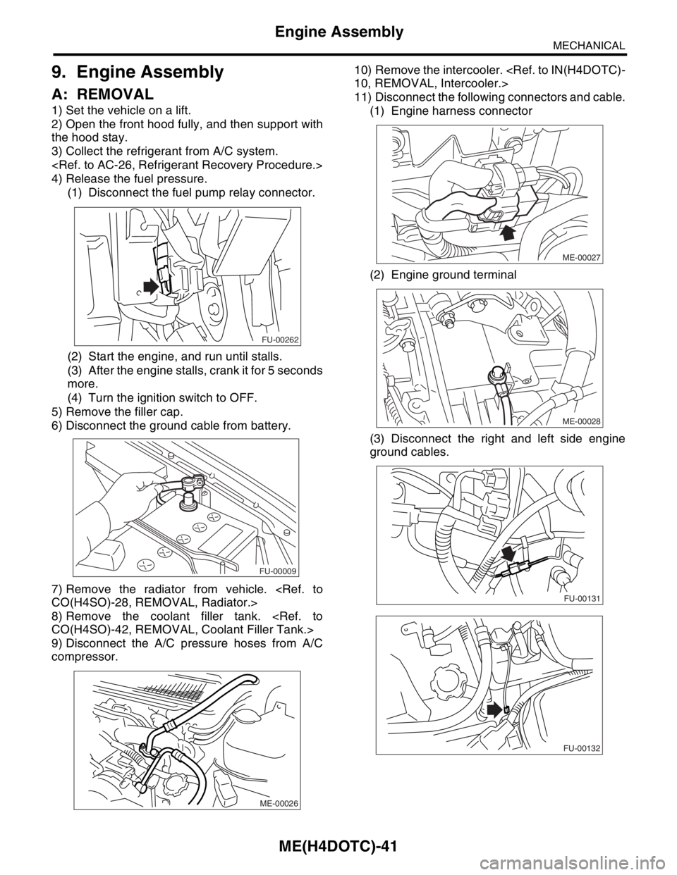
A: REMOVAL
1) Set the vehicle on a lift.
2) Open the front hood fully, and then support with
the hood stay.
3) Collect the refrigerant from A/C system.
4) Release the fuel pressure.
(1) Disconnect the fuel pump relay connector.
(2) Start the engine, and run until stalls.
(3) After the engine stalls, crank it for 5 seconds
more.
(4) Turn the ignition switch to OFF.
5) Remove the filler cap.
6) Disconnect the ground cable from battery.
7) Remove the radiator from vehicle.
8) Remove the coolant filler tank.
9) Disconnect the A/C pressure hoses from A/C
compressor.10) Remove the intercooler.
11) Disconnect the following connectors and cable.
(1) Engine harness connector
(2) Engine ground terminal
(3) Disconnect the right and left side engine
ground cables.
FU-00262
FU-00009
ME-00026
ME-00027
ME-00028
FU-00131
FU-00132
Page 1500 of 2870
ME(H4DOTC)-42
MECHANICAL
Engine Assembly
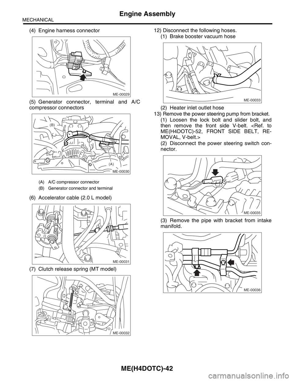
(4) Engine harness connector
(5) Generator connector, terminal and A/C
compressor connectors
(6) Accelerator cable (2.0 L model)
(7) Clutch release spring (MT model)12) Disconnect the following hoses.
(1) Brake booster vacuum hose
(2) Heater inlet outlet hose
13) Remove the power steering pump from bracket.
(1) Loosen the lock bolt and slider bolt, and
then remove the front side V-belt.
MOVAL, V-belt.>
(2) Disconnect the power steering switch con-
nector.
(3) Remove the pipe with bracket from intake
manifold.
(A) A/C compressor connector
(B) Generator connector and terminal
ME-00029
ME-00030
(A) (B)
ME-00031
ME-00032
ME-00033
ME-00035
ME-00036