SUBARU FORESTER 2004 Service Repair Manual
Manufacturer: SUBARU, Model Year: 2004, Model line: FORESTER, Model: SUBARU FORESTER 2004Pages: 2870, PDF Size: 38.67 MB
Page 1521 of 2870
ME(H4DOTC)-63
MECHANICAL
Timing Belt Assembly
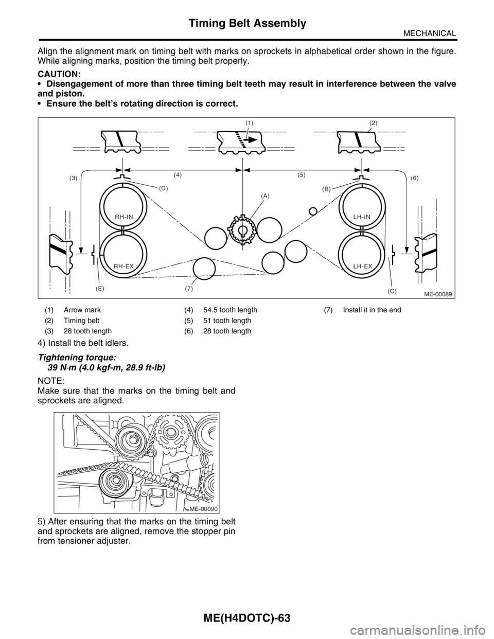
Align the alignment mark on timing belt with marks on sprockets in alphabetical order shown in the figure.
While aligning marks, position the timing belt properly.
CAUTION:
Disengagement of more than three timing belt teeth may result in interference between the valve
and piston.
Ensure the belt’s rotating direction is correct.
4) Install the belt idlers.
Tightening torque:
39 N
⋅m (4.0 kgf-m, 28.9 ft-lb)
NOTE:
Make sure that the marks on the timing belt and
sprockets are aligned.
5) After ensuring that the marks on the timing belt
and sprockets are aligned, remove the stopper pin
from tensioner adjuster.
(1) Arrow mark (4) 54.5 tooth length (7) Install it in the end
(2) Timing belt (5) 51 tooth length
(3) 28 tooth length (6) 28 tooth length
ME-00089 (1) (2)
(5)
(6) (4)
(D)
(A)
(C) (B)
(E) (3)
RH-IN
RH-EXLH-EX LH-IN
(7)
ME-00090
Page 1522 of 2870
ME(H4DOTC)-64
MECHANICAL
Timing Belt Assembly
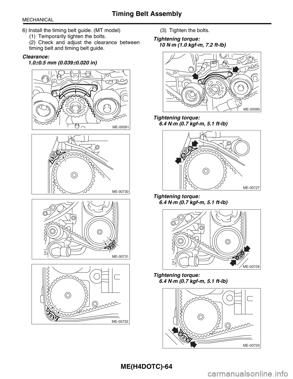
6) Install the timing belt guide. (MT model)
(1) Temporarily tighten the bolts.
(2) Check and adjust the clearance between
timing belt and timing belt guide.
Clearance:
1.0
±0.5 mm (0.039±0.020 in)(3) Tighten the bolts.
Tightening torque:
10 N
⋅m (1.0 kgf-m, 7.2 ft-lb)
Tightening torque:
6.4 N
⋅m (0.7 kgf-m, 5.1 ft-lb)
Tightening torque:
6.4 N
⋅m (0.7 kgf-m, 5.1 ft-lb)
Tightening torque:
6.4 N
⋅m (0.7 kgf-m, 5.1 ft-lb)
ME-00091
ME-00730
ME-00731
ME-00732
ME-00095
ME-00727
ME-00728
ME-00729
Page 1523 of 2870

ME(H4DOTC)-65
MECHANICAL
Timing Belt Assembly
7) Install the timing belt cover.
Cover.>
8) Install the crank pulley.
9) Install the V-belt.
C: INSPECTION
1. TIMING BELT
1) Check the timing belt teeth for breaks, cracks,
and wear. If any fault is found, replace the belt.
2) Check the condition of back side of belt; if any
crack is found, replace the belt.
NOTE:
Be careful not to let oil, grease or coolant contact
the belt. Remove quickly and thoroughly if this hap-
pens.
Do not bend the belt sharply.
Bending radius: h
60 mm (2.36 in) or more
2. AUTOMATIC BELT TENSION ADJUST-
ER
1) Visually check the oil seals for leaks, and rod
ends for abnormal wear or scratches. If necessary,
replace the automatic belt tension adjuster assem-
bly.
NOTE:
Slight traces of oil at rod’s oil seal does not indicate
a problem.
2) Check that the adjuster rod does not move when
a pressure of 294 N (30 kgf, 66 lb) is applied to it.
This is to check adjuster rod stiffness.
3) If the adjuster rod is not stiff and moves freely
when applying 294 N (30 kgf, 66 lb), check it using
the following procedures:
(1) Slowly press the adjuster rod down to the
end surface of the cylinder. Repeat this motion 2
or 3 times.
(2) With the adjuster rod moved all the way up,
apply a pressure of 294 N (30 kgf, 66 lb) to it.
Check the adjuster rod stiffness.(3) If the adjuster rod is not stiff and moves
down, replace the automatic belt tension adjust-
er assembly with a new one.
NOTE:
Always use a vertical type pressing tool to move
the adjuster rod down.
Do not use a lateral type vise.
Push the adjuster rod vertically.
Press-in the push adjuster rod gradually taking
more than 3 minutes.
Do not allow press pressure to exceed 9,807 N
(1,000 kgf, 2,205 lb).
Press the adjuster rod as far as the end surface
of the cylinder. Do not press the adjuster rod into
the cylinder. Doing so may damage the cylinder.
4) Measure the extension of rod beyond the body.
If it is not within specifications, replace with a new
one.
Rod extension: H
6.2
±0.5 mm (0.244±0.020 in)
3. BELT TENSION PULLEY
1) Check the mating surfaces of timing belt and
contact point of adjuster rod for abnormal wear or
scratches. Replace the belt tension pulley if faulty.
2) Check the belt tension pulley for smooth rota-
tion. Replace if noise or excessive play is noted.
3) Check the belt tension pulley for grease leakage.
4. BELT IDLER
1) Check the belt idler for smooth rotation. Replace
if noise or excessive play is noted.
2) Check the outer contacting surfaces of idler pul-
ley for abnormal wear and scratches.
3) Check the belt idler for grease leakage.
ME-00099
h
ME-00100
H
Page 1524 of 2870
ME(H4DOTC)-66
MECHANICAL
Cam Sprocket
16.Cam Sprocket
A: REMOVAL
1) Remove the V-belt.
2) Remove the crank pulley.
3) Remove the timing belt cover.
4) Remove the timing belt assembly.
bly.>
5) Remove the camshaft position sensor. (2.0 L
model)
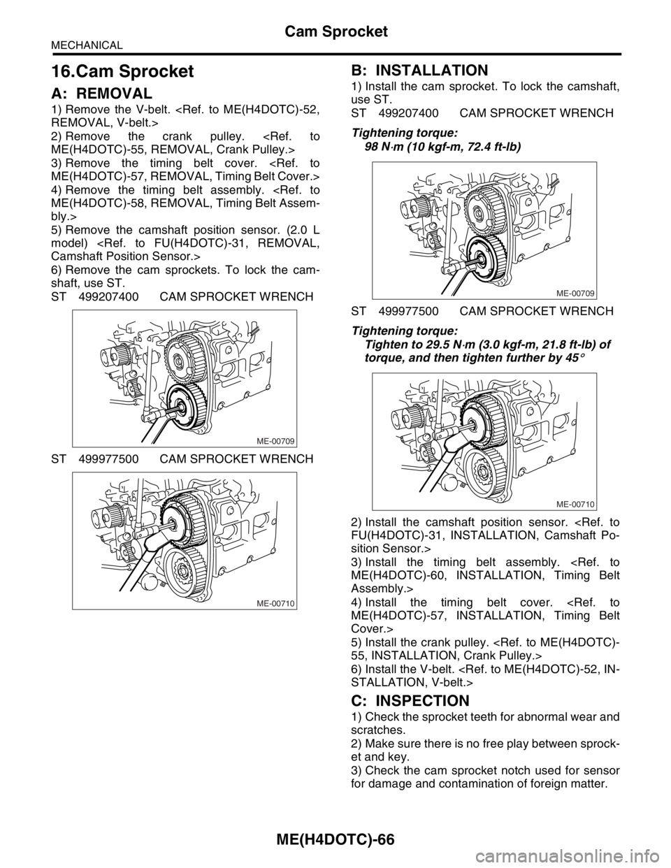
6) Remove the cam sprockets. To lock the cam-
shaft, use ST.
ST 499207400 CAM SPROCKET WRENCH
ST 499977500 CAM SPROCKET WRENCH
B: INSTALLATION
1) Install the cam sprocket. To lock the camshaft,
use ST.
ST 499207400 CAM SPROCKET WRENCH
Tightening torque:
98 N
⋅m (10 kgf-m, 72.4 ft-lb)
ST 499977500 CAM SPROCKET WRENCH
Tightening torque:
Tighten to 29.5 N
⋅m (3.0 kgf-m, 21.8 ft-lb) of
torque, and then tighten further by 45
°
2) Install the camshaft position sensor.
sition Sensor.>
3) Install the timing belt assembly.
Assembly.>
4) Install the timing belt cover.
Cover.>
5) Install the crank pulley.
6) Install the V-belt.
C: INSPECTION
1) Check the sprocket teeth for abnormal wear and
scratches.
2) Make sure there is no free play between sprock-
et and key.
3) Check the cam sprocket notch used for sensor
for damage and contamination of foreign matter.
ME-00709
ME-00710
ME-00709
ME-00710
Page 1525 of 2870
ME(H4DOTC)-67
MECHANICAL
Crank Sprocket
17.Crank Sprocket
A: REMOVAL
1) Remove the V-belt.
2) Remove the crank pulley.
3) Remove the timing belt cover.
4) Remove the timing belt assembly.
bly.>
5) Remove the cam sprocket.
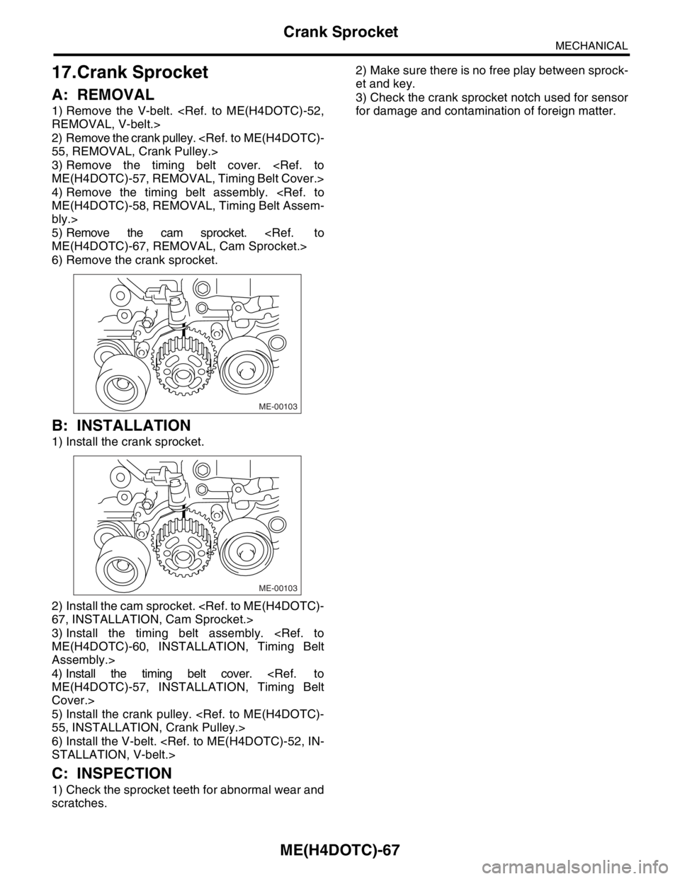
6) Remove the crank sprocket.
B: INSTALLATION
1) Install the crank sprocket.
2) Install the cam sprocket.
3) Install the timing belt assembly.
Assembly.>
4) Install the timing belt cover.
Cover.>
5) Install the crank pulley.
6) Install the V-belt.
C: INSPECTION
1) Check the sprocket teeth for abnormal wear and
scratches.2) Make sure there is no free play between sprock-
et and key.
3) Check the crank sprocket notch used for sensor
for damage and contamination of foreign matter.
ME-00103
ME-00103
Page 1526 of 2870
ME(H4DOTC)-68
MECHANICAL
Camshaft
18.Camshaft
A: REMOVAL
1) Remove the V-belt.
2) Remove the crank pulley.
3) Remove the timing belt cover.
4) Remove the timing belt assembly.
bly.>
5) Remove the cam sprocket.
6) Remove the crank sprocket.
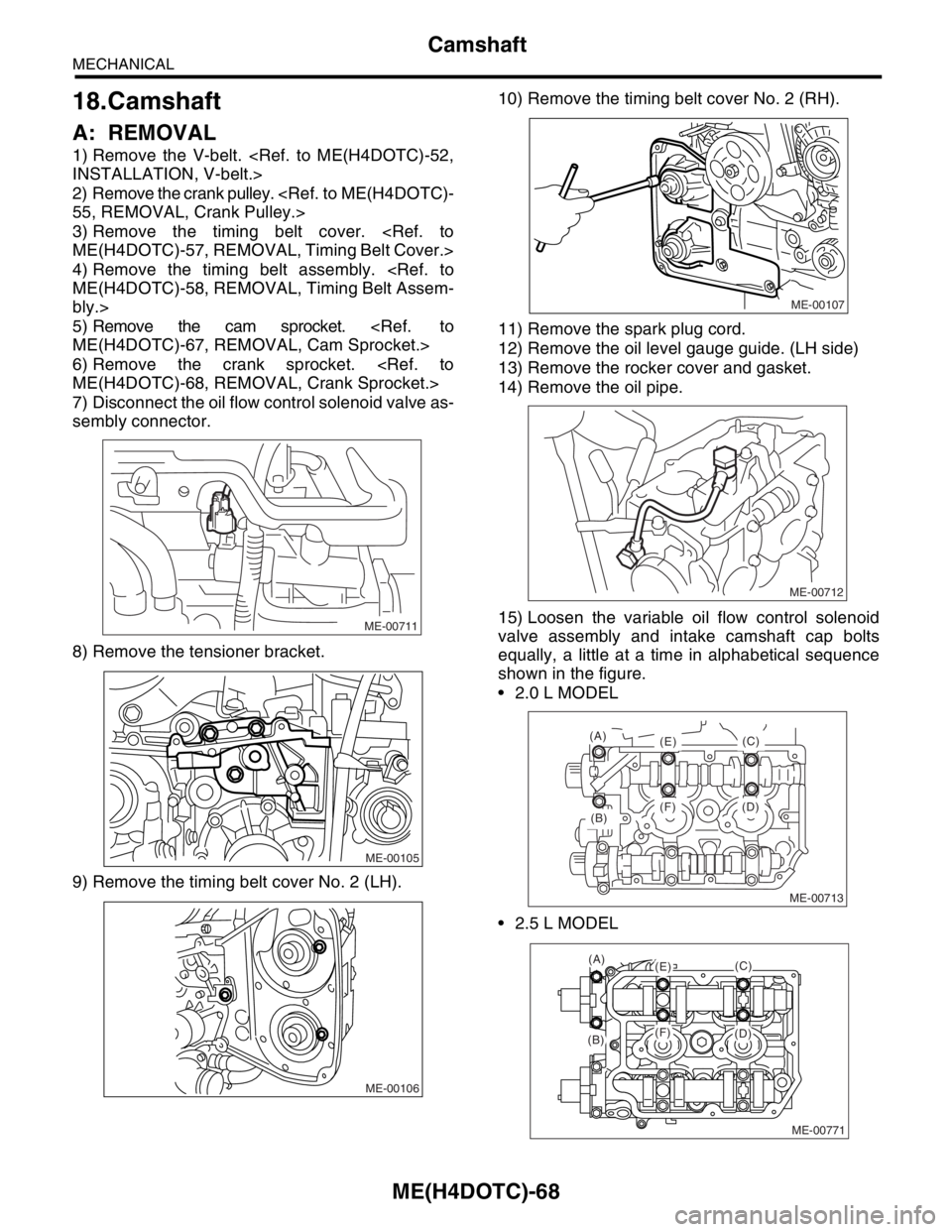
7) Disconnect the oil flow control solenoid valve as-
sembly connector.
8) Remove the tensioner bracket.
9) Remove the timing belt cover No. 2 (LH).10) Remove the timing belt cover No. 2 (RH).
11) Remove the spark plug cord.
12) Remove the oil level gauge guide. (LH side)
13) Remove the rocker cover and gasket.
14) Remove the oil pipe.
15) Loosen the variable oil flow control solenoid
valve assembly and intake camshaft cap bolts
equally, a little at a time in alphabetical sequence
shown in the figure.
2.0 L MODEL
2.5 L MODEL
ME-00711
ME-00105
ME-00106
ME-00107
ME-00712
ME-00713
(B)
(A)
(E)
(F) (D)(C)
ME-00771
(A)(E)
(F)(B)(D)
(C)
Page 1527 of 2870
ME(H4DOTC)-69
MECHANICAL
Camshaft
16) Remove the oil flow control solenoid valve as-
sembly, intake camshaft cap, and camshaft.
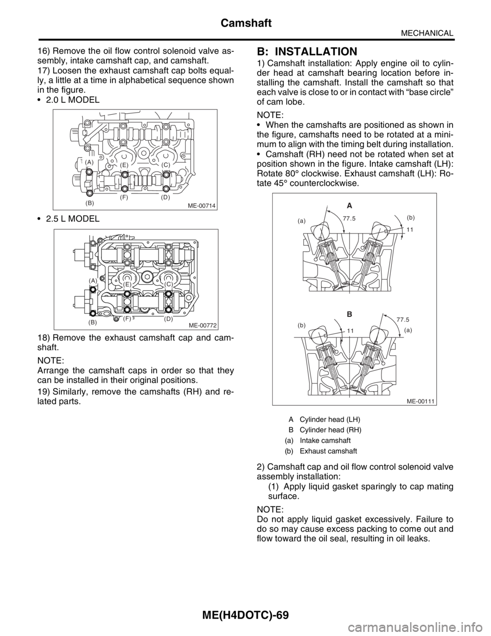
17) Loosen the exhaust camshaft cap bolts equal-
ly, a little at a time in alphabetical sequence shown
in the figure.
2.0 L MODEL
2.5 L MODEL
18) Remove the exhaust camshaft cap and cam-
shaft.
NOTE:
Arrange the camshaft caps in order so that they
can be installed in their original positions.
19) Similarly, remove the camshafts (RH) and re-
lated parts.B: INSTALLATION
1) Camshaft installation: Apply engine oil to cylin-
der head at camshaft bearing location before in-
stalling the camshaft. Install the camshaft so that
each valve is close to or in contact with “base circle”
of cam lobe.
NOTE:
When the camshafts are positioned as shown in
the figure, camshafts need to be rotated at a mini-
mum to align with the timing belt during installation.
Camshaft (RH) need not be rotated when set at
position shown in the figure. Intake camshaft (LH):
Rotate 80° clockwise. Exhaust camshaft (LH): Ro-
tate 45° counterclockwise.
2) Camshaft cap and oil flow control solenoid valve
assembly installation:
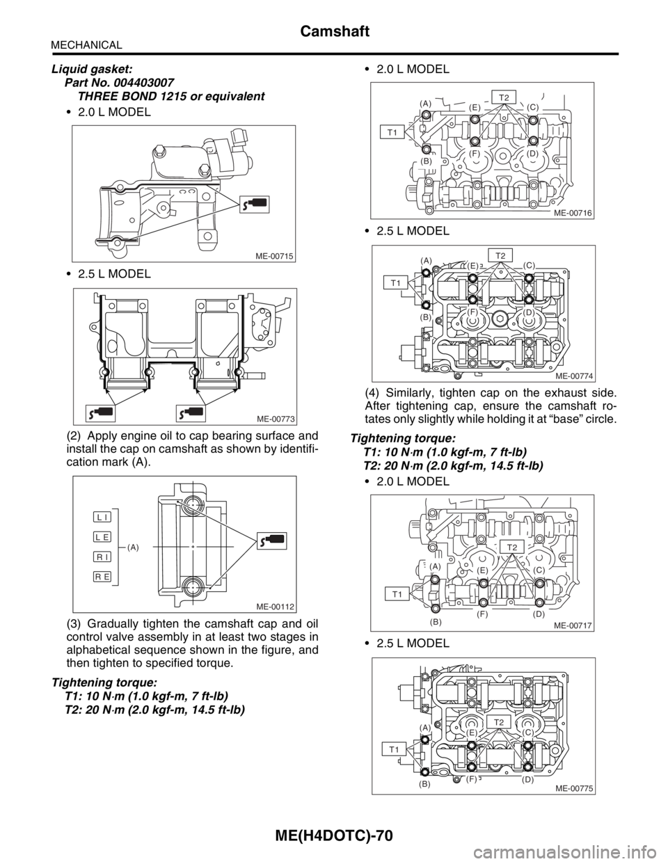
(1) Apply liquid gasket sparingly to cap mating
surface.
NOTE:
Do not apply liquid gasket excessively. Failure to
do so may cause excess packing to come out and
flow toward the oil seal, resulting in oil leaks.
ME-00714(B)
(A)
(E)
(F) (D)(C)
ME-00772
(A)(E)
(F)(B)(D)
(C)
A Cylinder head (LH)
B Cylinder head (RH)
(a) Intake camshaft
(b) Exhaust camshaft
ME-00111
1111
77.5 77.5
(a)
(b)
(a)(b)
A
B
Page 1528 of 2870
ME(H4DOTC)-70
MECHANICAL
Camshaft
Liquid gasket:
Part No. 004403007
THREE BOND 1215 or equivalent
2.0 L MODEL
2.5 L MODEL
(2) Apply engine oil to cap bearing surface and
install the cap on camshaft as shown by identifi-
cation mark (A).
(3) Gradually tighten the camshaft cap and oil
control valve assembly in at least two stages in
alphabetical sequence shown in the figure, and
then tighten to specified torque.
Tightening torque:
T1: 10 N
⋅m (1.0 kgf-m, 7 ft-lb)
T2: 20 N
⋅m (2.0 kgf-m, 14.5 ft-lb) 2.0 L MODEL
2.5 L MODEL
(4) Similarly, tighten cap on the exhaust side.
After tightening cap, ensure the camshaft ro-
tates only slightly while holding it at “base” circle.
Tightening torque:
T1: 10 N
⋅m (1.0 kgf-m, 7 ft-lb)
T2: 20 N
⋅m (2.0 kgf-m, 14.5 ft-lb)
2.0 L MODEL
2.5 L MODEL
ME-00715
ME-00773
ME-00112
L E
R E
R I
L I
(A)
(B)
(A)
(E)
(F) (D)(C)
T1
ME-00716
T2
ME-00774
(A)(E)
(F)(B)(D)
(C)T2
T1
ME-00717(B)
(A)
(E)
(F) (D)(C)
T2
T1
ME-00775
(A)(E)
(F)(B)(D)
(C)T2
T1
Page 1529 of 2870
ME(H4DOTC)-71
MECHANICAL
Camshaft
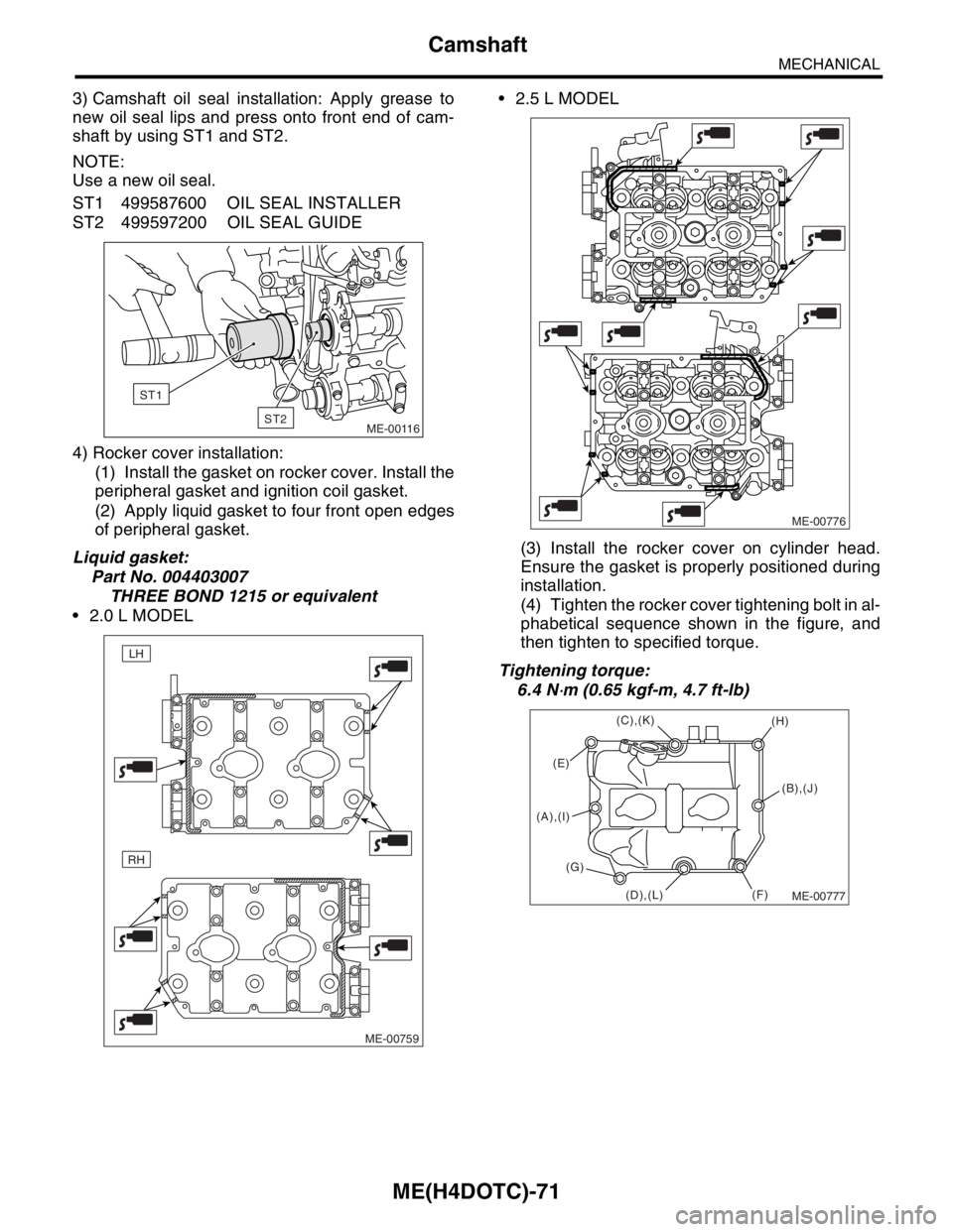
3) Camshaft oil seal installation: Apply grease to
new oil seal lips and press onto front end of cam-
shaft by using ST1 and ST2.
NOTE:
Use a new oil seal.
ST1 499587600 OIL SEAL INSTALLER
ST2 499597200 OIL SEAL GUIDE
4) Rocker cover installation:
(1) Install the gasket on rocker cover. Install the
peripheral gasket and ignition coil gasket.
(2) Apply liquid gasket to four front open edges
of peripheral gasket.
Liquid gasket:
Part No. 004403007
THREE BOND 1215 or equivalent
2.0 L MODEL 2.5 L MODEL
(3) Install the rocker cover on cylinder head.
Ensure the gasket is properly positioned during
installation.
(4) Tighten the rocker cover tightening bolt in al-
phabetical sequence shown in the figure, and
then tighten to specified torque.
Tightening torque:
6.4 N
⋅m (0.65 kgf-m, 4.7 ft-lb)
ME-00116
ST1
ST2
ME-00759
RH
LH
ME-00776
ME-00777
(E)
(F)(H)
(G)
(D),(L) (A),(I)(C),(K)
(B),(J)
Page 1530 of 2870
ME(H4DOTC)-72
MECHANICAL
Camshaft
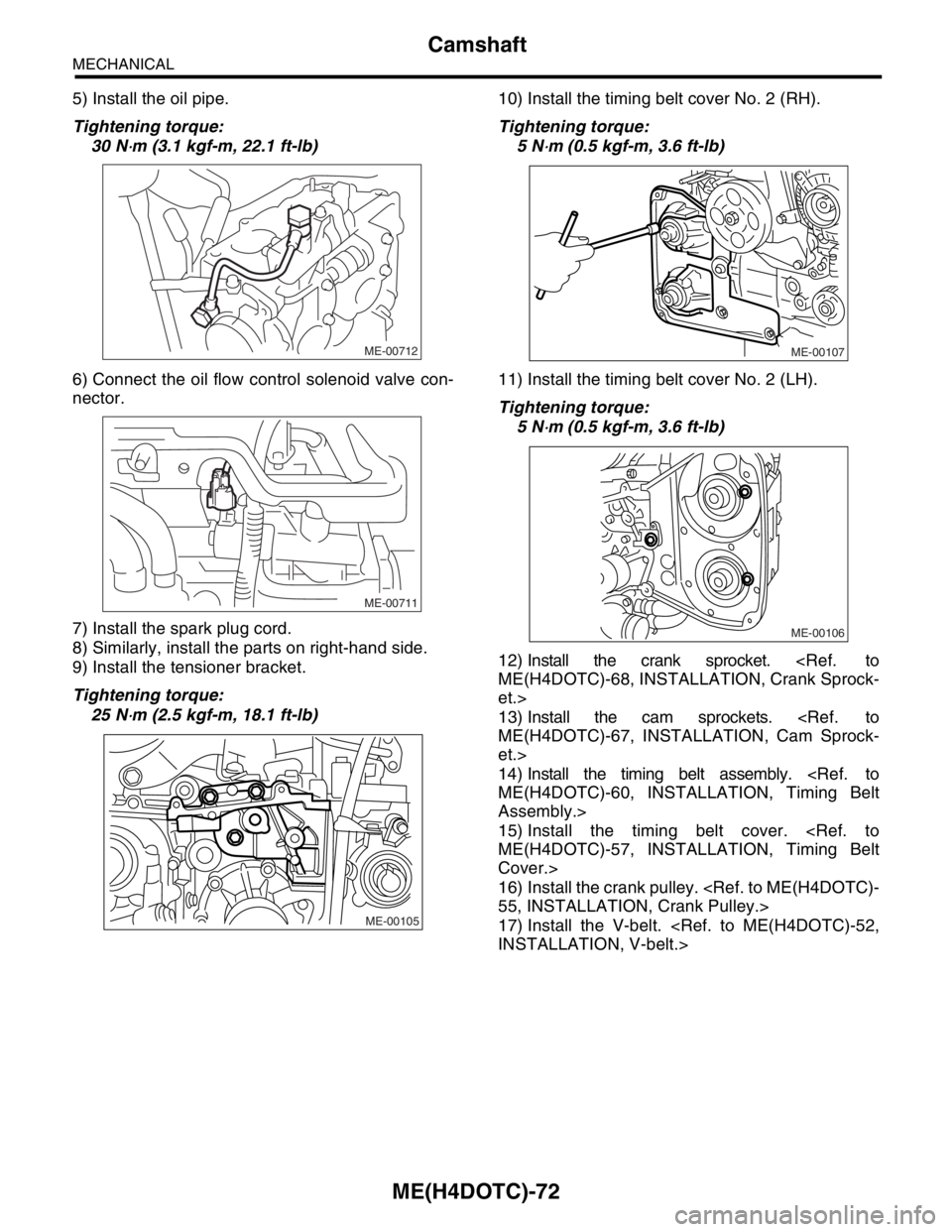
5) Install the oil pipe.
Tightening torque:
30 N
⋅m (3.1 kgf-m, 22.1 ft-lb)
6) Connect the oil flow control solenoid valve con-
nector.
7) Install the spark plug cord.
8) Similarly, install the parts on right-hand side.
9) Install the tensioner bracket.
Tightening torque:
25 N
⋅m (2.5 kgf-m, 18.1 ft-lb)10) Install the timing belt cover No. 2 (RH).
Tightening torque:
5 N
⋅m (0.5 kgf-m, 3.6 ft-lb)
11) Install the timing belt cover No. 2 (LH).
Tightening torque:
5 N
⋅m (0.5 kgf-m, 3.6 ft-lb)
12) Install the crank sprocket.
et.>
13) Install the cam sprockets.
et.>
14) Install the timing belt assembly.
Assembly.>
15) Install the timing belt cover.
Cover.>
16) Install the crank pulley.
17) Install the V-belt.
ME-00712
ME-00711
ME-00105
ME-00107
ME-00106