SUBARU FORESTER 2004 Service Repair Manual
FORESTER 2004
SUBARU
SUBARU
https://www.carmanualsonline.info/img/17/57426/w960_57426-0.png
SUBARU FORESTER 2004 Service Repair Manual
Trending: horn, display, navigation system, rear turn signal, overheating, ESP inoperative, radiator cap
Page 1911 of 2870
EN(H4DOTC)-278
ENGINE (DIAGNOSTIC)
Diagnostic Procedure with Diagnostic Trouble Code (DTC)
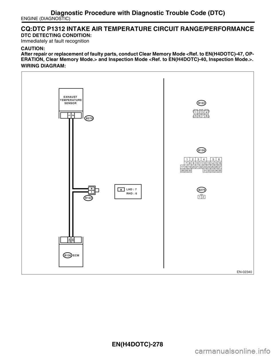
CQ:DTC P1312 INTAKE AIR TEMPERATURE CIRCUIT RANGE/PERFORMANCE
DTC DETECTING CONDITION:
Immediately at fault recognition
CAUTION:
After repair or replacement of faulty parts, conduct Clear Memory Mode
ERATION, Clear Memory Mode.> and Inspection Mode .
WIRING DIAGRAM:
EN-02340
B122
1*
B136 ECM
35 24
B279 EXHAUST
TEMPERATURE
SENSOR1
2
B279
12
B136
LHD : 7
RHD : 6*
B122
12345678
56
782 1
94 310
24 22 23 2511 12 13
1415
26 27
2816
17 18 19 20 21
33 34 29
32 30
31 35
Page 1912 of 2870
EN(H4DOTC)-279
ENGINE (DIAGNOSTIC)
Diagnostic Procedure with Diagnostic Trouble Code (DTC)
Step Check Yes No
1 CHECK ANY OTHER DTC ON DISPLAY.Is any other DTC displayed? Inspect the rele-
vant DTC using
“List of Diagnostic
Trouble Code
(DTC)”.
EN(H4DOTC)-74,
List of Diagnostic
Trouble Code
(DTC).>
N
OTE:
In this case, it is
not necessary to
inspect DTC
P1312.Replace the
exhaust tempera-
ture sensor.
to FU(H4DOTC)-
49, Exhaust Tem-
perature Sensor.>
Page 1913 of 2870
EN(H4DOTC)-280
ENGINE (DIAGNOSTIC)
Diagnostic Procedure with Diagnostic Trouble Code (DTC)
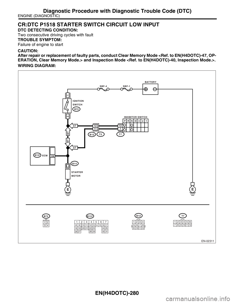
CR:DTC P1518 STARTER SWITCH CIRCUIT LOW INPUT
DTC DETECTING CONDITION:
Two consecutive driving cycles with fault
TROUBLE SYMPTOM:
Failure of engine to start
CAUTION:
After repair or replacement of faulty parts, conduct Clear Memory Mode
ERATION, Clear Memory Mode.> and Inspection Mode .
WIRING DIAGRAM:
EN-02311
BATTERY
INHIBITOR SWITCH
IGNITION
SWITCH
STARTER
MOTOR
SBF-4SBF-1
B72
B72
B14
B137
ECM
EE
1
3
D8
3412
B137
T3B12MT
AT
AT
MT
1112712
PR
N
D3
21
T7
B12
123
8
9
10
4
11
1256
7
T7
123
8910411 1256
7567
82 1
94 310
22 23 11 12 13 14 15
24 25
2616 17
18 19 20 21
27 28 29 30 31
Page 1914 of 2870
EN(H4DOTC)-281
ENGINE (DIAGNOSTIC)
Diagnostic Procedure with Diagnostic Trouble Code (DTC)
Step Check Yes No
1 CHECK OPERATION OF STARTER MOTOR.Does the starter motor operate
when ignition switch to
START?Repair the har-
ness and connec-
tor.
N
OTE:
In this case repair
the following:
Open or ground
short circuit in har-
ness between
ECM and starter
motor connector.
Poor contact in
ECM connector.Check starter
motor circuit.
to EN(H4DOTC)-
60, STARTER
MOTOR CIR-
CUIT, Diagnostics
for Engine Start-
ing Failure.>
Page 1915 of 2870
EN(H4DOTC)-282
ENGINE (DIAGNOSTIC)
Diagnostic Procedure with Diagnostic Trouble Code (DTC)
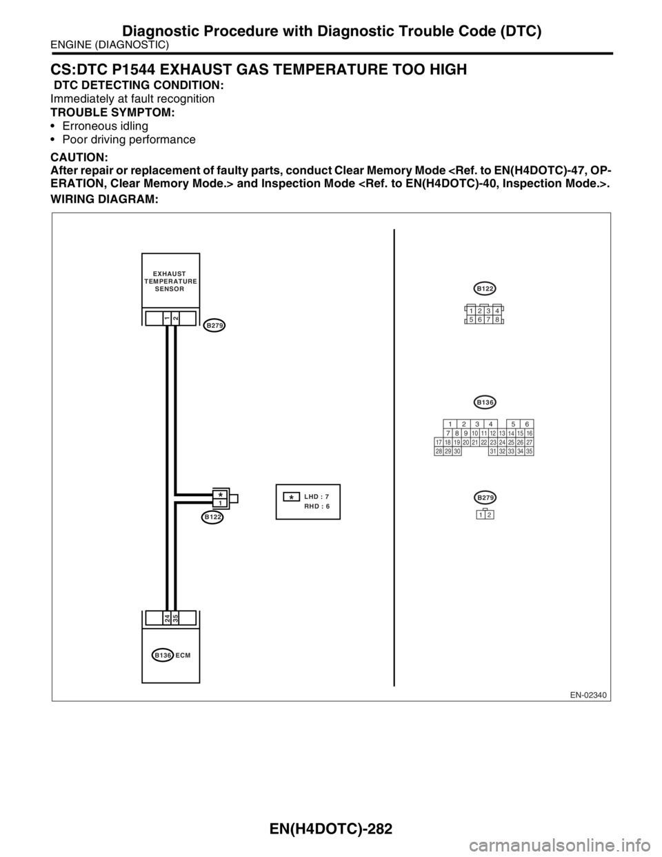
CS:DTC P1544 EXHAUST GAS TEMPERATURE TOO HIGH
DTC DETECTING CONDITION:
Immediately at fault recognition
TROUBLE SYMPTOM:
Erroneous idling
Poor driving performance
CAUTION:
After repair or replacement of faulty parts, conduct Clear Memory Mode
ERATION, Clear Memory Mode.> and Inspection Mode .
WIRING DIAGRAM:
EN-02340
B122
1*
B136 ECM
35 24
B279 EXHAUST
TEMPERATURE
SENSOR1
2
B279
12
B136
LHD : 7
RHD : 6*
B122
12345678
56
782 1
94 310
24 22 23 2511 12 13
1415
26 27
2816
17 18 19 20 21
33 34 29
32 30
31 35
Page 1916 of 2870
EN(H4DOTC)-283
ENGINE (DIAGNOSTIC)
Diagnostic Procedure with Diagnostic Trouble Code (DTC)
Step Check Yes No
1 CHECK ANY OTHER DTC ON DISPLAY.Is any other DTC displayed? Inspect the rele-
vant DTC using
“List of Diagnostic
Trouble Code
(DTC)”.
EN(H4DOTC)-74,
List of Diagnostic
Trouble Code
(DTC).>
N
OTE:
In this case, it is
not necessary to
inspect DTC
P1544.Go to step 2.
2 CHECK EXHAUST SYSTEM.
Check exhaust system parts.
NOTE:
Check the following items:
Loose installation of exhaust manifold
Cracks or hole of exhaust manifold
Loose installation of front oxygen (A/F) sen-
sorIs there a fault in exhaust sys-
tem?Repair or replace
failure, then
replace the precat-
alytic converter.Contact the SUB-
ARU dealer.
NOTE:
Inspection by DTM
is required, be-
cause probable
cause is deteriora-
tion of multiple
parts.
Page 1917 of 2870
EN(H4DOTC)-284
ENGINE (DIAGNOSTIC)
Diagnostic Procedure with Diagnostic Trouble Code (DTC)
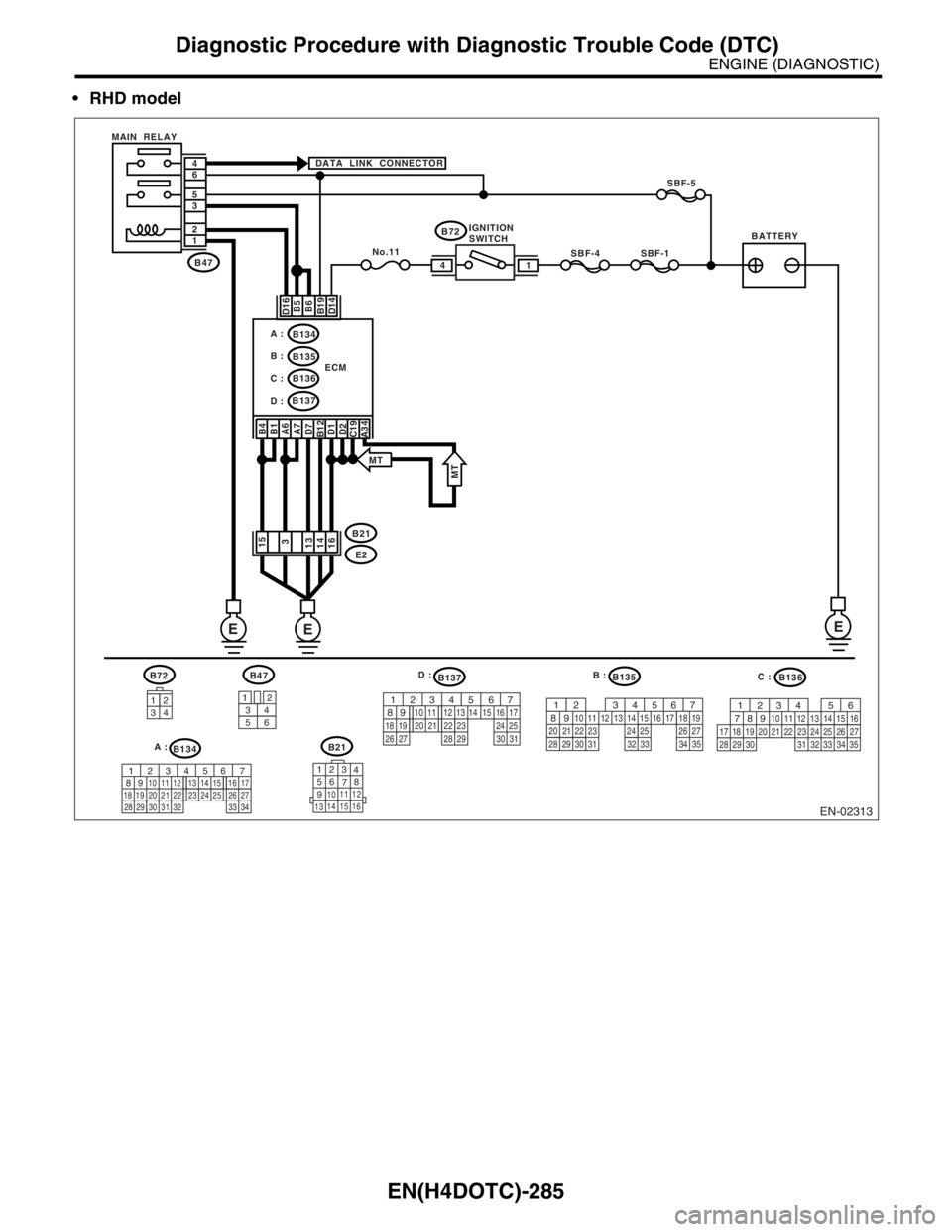
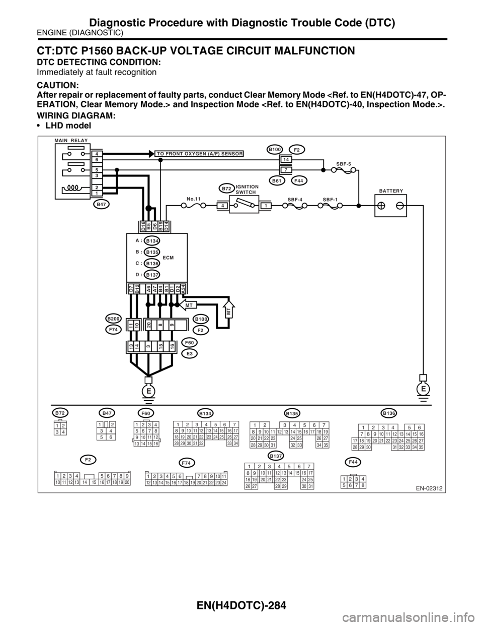
CT:DTC P1560 BACK-UP VOLTAGE CIRCUIT MALFUNCTION
DTC DETECTING CONDITION:
Immediately at fault recognition
CAUTION:
After repair or replacement of faulty parts, conduct Clear Memory Mode
ERATION, Clear Memory Mode.> and Inspection Mode .
WIRING DIAGRAM:
LHD model
EN-02312
F74
B72
34
12
BATTERYIGNITION
SWITCH MAIN RELAY
SBF-4SBF-1
SBF-5
B72 TO FRONT OXYGEN (A/F) SENSOR
D16 D7
B12
A6
A7
B4
B1
D1
D2
A34B5
D6
B19
D14
No.11
B61F44
B47
B100
F2
E3 F60 1 2 3 5 6 4
ECM
EE
14
B134
B137 B135 A :
B :
C :B136
D :
14
7
3412
56
123
4
56
78
9
1011 12
1314 15 16
F60B47
B137
F2
B100F2
11
10
20
8
9 13
14
3
15
16
B135
F44
567
82 1
94 310
24 22 23 2511 12 13 14 15
26 27
2816 17 18 19
20 21
29 30 31 32 33 34 35
12345678
34
12 8910 11
12 13 14 15 16 17 18 19 20 21 22 23 2456 71234 5678910 11 12 13 14 15 16 17 18 19 20
567
82 1
94 310
22 23 11 12 13 14 15
24 25
2616 17
18 19 20 21
27 28 29 30 31
F74 B200
MT
MT
B134
56 7
82 1
94 310
24 22 23 25 11 12 13 14 15
26 27
2816 17
18 19 20 21
33 34 29
32 30 31
B136
56
782 1
94 310
24 22 23 2511 12 13
1415
26 27
2816
17 18 19 20 21
33 34 29
32 30
31 35
Page 1918 of 2870
EN(H4DOTC)-285
ENGINE (DIAGNOSTIC)
Diagnostic Procedure with Diagnostic Trouble Code (DTC)
RHD model
B72B136
34
12
BATTERYIGNITION
SWITCH MAIN RELAY
SBF-4SBF-1
SBF-5
B72 DATA LINK CONNECTOR
D16 B4
B1
A6
A7
D7
B12
D1
D2
C19B5
B6
B19
D14
No.11B47
E2 B21 1 2 3 5 6 4
ECM
14
B134
B135
B136 A :
B :
C :
B137
D :
15
3
16 14 13
3412
56
123
4
56
78
9
1011 12
1314 15 16
B134B21
B47B135B137
EN-02313
E
E E
567
82 1
94 310
24 22 23 2511 12 13 14 15
26 27
2816 17 18 19
20 21
29 30 31 32 33 34 35
567
82 1
94 310
22 23 11 12 13 14 15
24 25
2616 17
18 19 20 21
27 28 29 30 31
A34
MTMT
56
782 1
94 310
24 22 23 2511 12 13
1415
26 27
2816
17 18 19 20 21
33 34 29
32 30
31 35
56 7
82 1
94 310
24 22 23 25 11 12 13 14 15
26 27
2816 17
18 19 20 21
33 34 29
32 30 31
D :
B :
C :
A :
Page 1919 of 2870

EN(H4DOTC)-286
ENGINE (DIAGNOSTIC)
Diagnostic Procedure with Diagnostic Trouble Code (DTC)
Step Check Yes No
1 CHECK INPUT SIGNAL FROM ECM.
1) Turn the ignition switch to OFF.
2) Measure the voltage between ECM and
chassis ground.
Connector & terminal
(B135) No. 19 (+) — Chassis ground (
−):Is the voltage more than 10 V? Repair the poor
contact in ECM
connector.Go to step 2.
2 CHECK HARNESS BETWEEN ECM AND
MAIN FUSE BOX CONNECTOR.
1) Disconnect the connector from ECM.
2) Measure the resistance of harness
between ECM and chassis ground.
Connector & terminal
(B135) No. 19 — Chassis ground:Is the resistance less than 10
Ω?Repair ground
short circuit in har-
ness between
ECM connector
and battery termi-
nal.Go to step 3.
3 CHECK FUSE SBF-5.Is the fuse blown out? Replace the fuse. Repair the har-
ness and connec-
tor.
N
OTE:
In this case repair
the following:
Open circuit in
harness between
ECM and battery
Poor contact in
ECM connector.
Poor contact in
battery terminal
Page 1920 of 2870
EN(H4DOTC)-287
ENGINE (DIAGNOSTIC)
Diagnostic Procedure with Diagnostic Trouble Code (DTC)
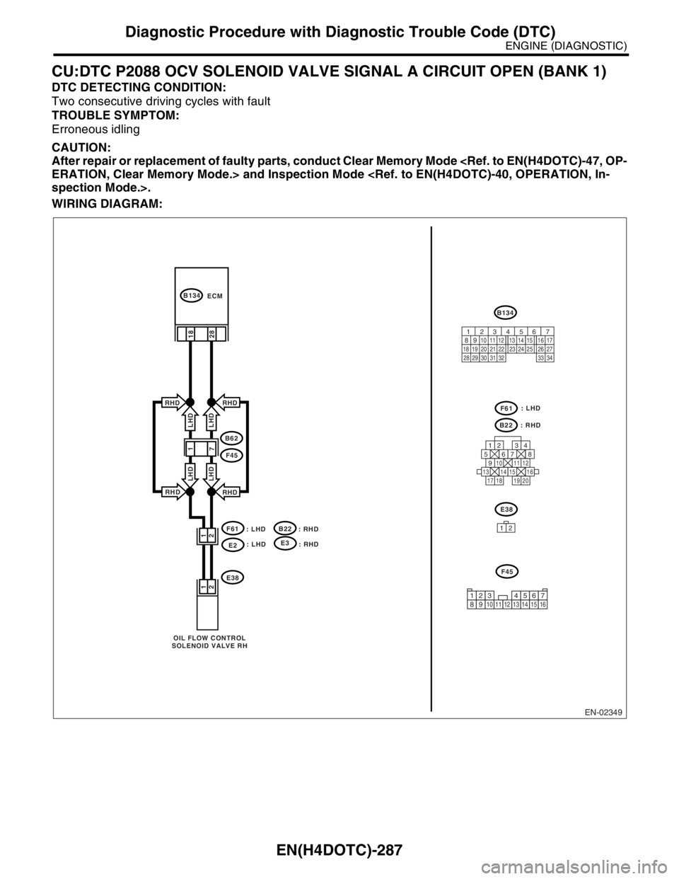
CU:DTC P2088 OCV SOLENOID VALVE SIGNAL A CIRCUIT OPEN (BANK 1)
DTC DETECTING CONDITION:
Two consecutive driving cycles with fault
TROUBLE SYMPTOM:
Erroneous idling
CAUTION:
After repair or replacement of faulty parts, conduct Clear Memory Mode
ERATION, Clear Memory Mode.> and Inspection Mode
spection Mode.>.
WIRING DIAGRAM:
EN-02349
F61
: LHD
E2
B134
B134
E38
OIL FLOW CONTROL
SOLENOID VALVE RHECM
28 2 1
2
1
B62
F45
RHD
RHD
LHD LHD
RHD
RHD
LHD LHD
: LHD
: RHD
B22
E38
F61
12
F45
B22
: RHD
18
125678
131415169101112
34
17181920
56 7
82 1
94 310
24 22 23 25 11 12 13 14 15
26 27
2816 17
18 19 20 21
33 34 29
32 30 31
12345678910111213141516
: LHDE3
: RHD
1
7
Trending: door lock, octane, relay, roof rack, clock setting, air bleeding, inflation pressure
