SUBARU FORESTER 2004 Service Repair Manual
Manufacturer: SUBARU, Model Year: 2004, Model line: FORESTER, Model: SUBARU FORESTER 2004Pages: 2870, PDF Size: 38.67 MB
Page 1881 of 2870
EN(H4DOTC)-248
ENGINE (DIAGNOSTIC)
Diagnostic Procedure with Diagnostic Trouble Code (DTC)
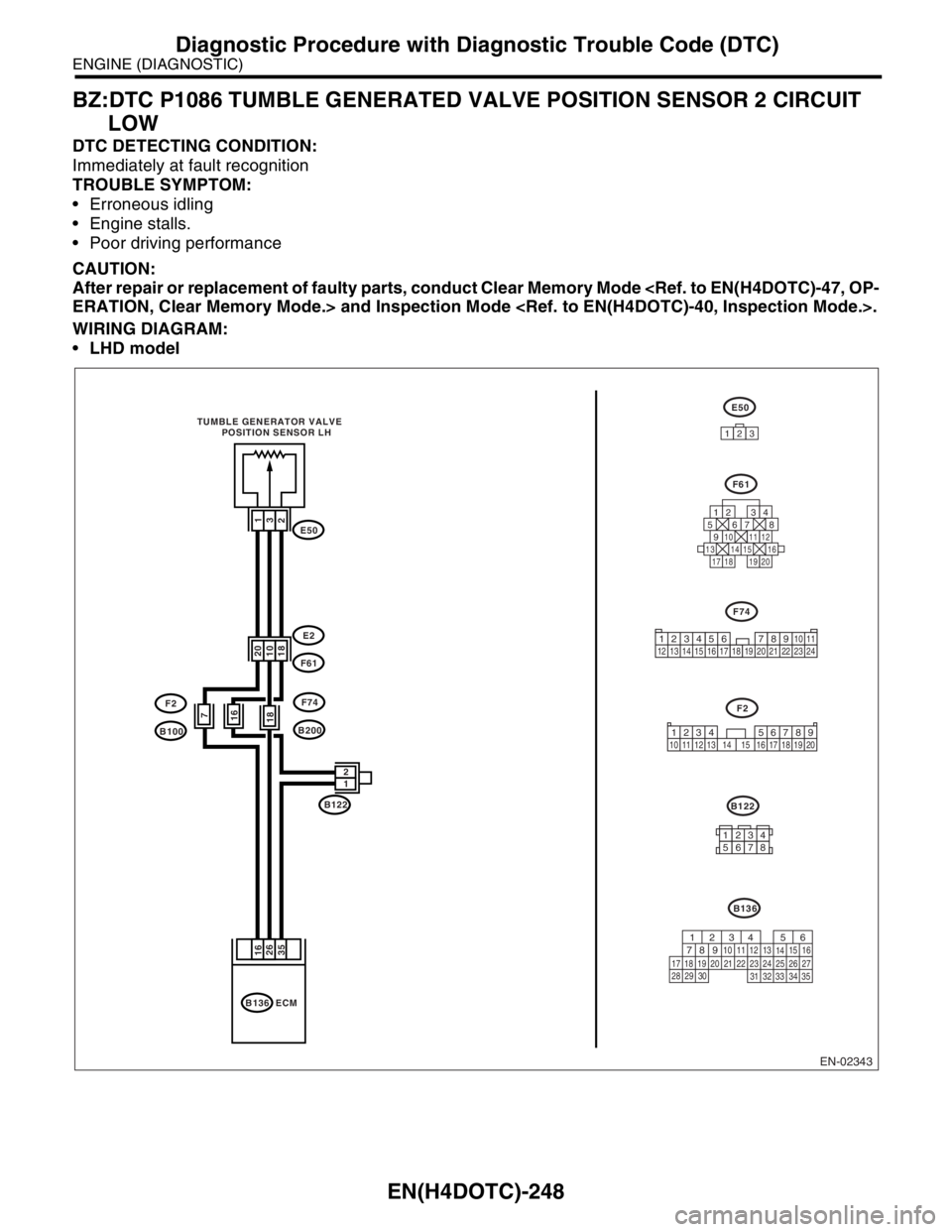
BZ:DTC P1086 TUMBLE GENERATED VALVE POSITION SENSOR 2 CIRCUIT
LOW
DTC DETECTING CONDITION:
Immediately at fault recognition
TROUBLE SYMPTOM:
Erroneous idling
Engine stalls.
Poor driving performance
CAUTION:
After repair or replacement of faulty parts, conduct Clear Memory Mode
WIRING DIAGRAM:
LHD model
EN-02343
E2
E50
F61
F74
B200
F2
B100
B122 TUMBLE GENERATOR VALVE
POSITION SENSOR LH
1
32
20
1018
1 2
B136 ECM
16
35 26
B136
E50
123
F61
F74
F2
125678
131415169101112
34
17181920
B122
34
12 8910 11
12 13 14 15 16 17 18 19 20 21 22 23 2456 7
1234 5678910 11 12 13 14 15 16 17 18 19 20
12345678
56
782 1
94 310
24 22 23 2511 12 13
1415
26 27
2816
17 18 19 20 21
33 34 29
32 30
31 35
187
16
Page 1882 of 2870
EN(H4DOTC)-249
ENGINE (DIAGNOSTIC)
Diagnostic Procedure with Diagnostic Trouble Code (DTC)
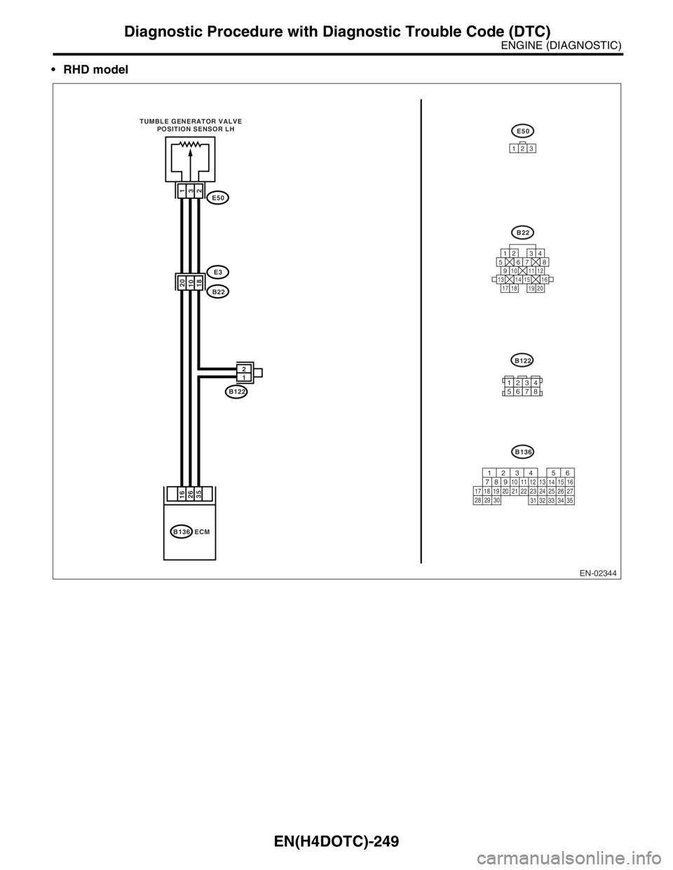
RHD model
EN-02344
E3
E50
B22
B122
1
32
20
1018
1 2
B136 ECM
16
35 26
B136
E50
123
B22
125678
131415169101112
34
17181920
B122 TUMBLE GENERATOR VALVE
POSITION SENSOR LH
56
782 1
94 310
24 22 23 2511 12 13
1415
26 27
2816
17 18 19 20 21
33 34 29
32 30
31 35
12345678
Page 1883 of 2870

EN(H4DOTC)-250
ENGINE (DIAGNOSTIC)
Diagnostic Procedure with Diagnostic Trouble Code (DTC)
Step Check Yes No
1 CHECK CURRENT DATA.
1) Start the engine.
2) Read the data of throttle position sensor
signal using Subaru Select Monitor or OBD-II
general scan tool.
N
OTE:
Subaru Select Monitor
For detailed operation procedure, refer to
“READ CURRENT DATA SHOWN ON DIS-
PLAY FOR ENGINE”.
OBD-II general scan tool
For detailed operation procedures, refer to the
OBD-II General Scan Tool Operation Manual.Is the voltage less than 0.1 V? Go to step 2.Even if the mal-
function indicator
light illuminates,
the circuit has
returned to a nor-
mal condition at
this time.A tempo-
rary poor contact
of the connector
may be the cause.
N
OTE:
In this case repair
the following:
Poor contact in
throttle position
sensor connector
Poor contact in
ECM connector.
Poor contact in
coupling connector
2 CHECK INPUT SIGNAL FROM ECM.
Measure the voltage between ECM connector
and chassis ground while tumble generator
valve is fully closed.
Connector & terminal
(B136) No. 16 (+) — Chassis ground (
−):Is the voltage more than 4.5 V? Go to step 4.Go to step 3.
3 CHECK INPUT SIGNAL FROM ECM.
Measure the voltage between ECM connector
and chassis ground.
Connector & terminal
(B136) No. 16 (+) — Chassis ground (
−):Does the voltage change by
shaking the harness and con-
nector of ECM while monitor-
ing the value with voltage
meter?Repair the poor
contact in ECM
connector.Contact the SUB-
ARU dealer.
N
OTE:
Inspection by DTM
is required, be-
cause probable
cause is deteriora-
tion of multiple
parts.
4 CHECK INPUT SIGNAL FROM ECM.
Measure the voltage between ECM connector
and chassis ground.
Connector & terminal
(B136) No. 26 (+) — Chassis ground (
−):Is the voltage less than 0.1 V? Go to step 6.Go to step 5.
5 CHECK INPUT SIGNAL FOR ECM (WITH
SUBARU SELECT MONITOR).
Measure the voltage between ECM connector
and chassis ground.Does the voltage change by
shaking the harness and con-
nector of ECM while monitor-
ing the value with Subaru
Select Monitor?Repair the poor
contact in ECM
connector.Go to step 6.
Page 1884 of 2870

EN(H4DOTC)-251
ENGINE (DIAGNOSTIC)
Diagnostic Procedure with Diagnostic Trouble Code (DTC)
6 CHECK HARNESS BETWEEN ECM AND
TUMBLE GENERATOR VALVE POSITION
SENSOR CONNECTOR.
1) Turn the ignition switch to OFF.
2) Disconnect the connector from tumble gen-
erator valve position sensor.
3) Turn the ignition switch to ON.
4) Measure the voltage between tumble gen-
erator valve position sensor connector and
engine ground.
Connector & terminal
(E50) No. 1 (+) — Engine ground (
−):Is the voltage more than 4.5 V? Go to step 7.Repair the har-
ness and connec-
tor.
N
OTE:
In this case repair
the following:
Open circuit in
harness between
tumble generator
valve position sen-
sor and ECM con-
nector
Poor contact in
tumble generator
valve position sen-
sor connector
Poor contact in
ECM connector.
Poor contact in
coupling connector
Poor contact in
joint connector
7 CHECK HARNESS BETWEEN ECM AND
TUMBLE GENERATOR VALVE POSITION
SENSOR CONNECTOR.
1) Turn the ignition switch to OFF.
2) Measure the resistance of harness
between ECM connector and tumble generator
valve position sensor connector.
Connector & terminal
(B136) No. 26 — (E50) No. 3:Is the resistance less than 1
Ω?Go to step 8.Repair the har-
ness and connec-
tor.
NOTE:
In this case repair
the following:
Open circuit in
harness between
tumble generator
valve position sen-
sor and ECM con-
nector
Poor contact in
ECM connector.
Poor contact in
tumble generator
valve position sen-
sor connector
Poor contact in
coupling connector
8 CHECK HARNESS BETWEEN ECM AND
TUMBLE GENERATOR VALVE POSITION
SENSOR CONNECTOR.
Measure the resistance of harness between
tumble generator valve position sensor con-
nector and engine ground.
Connector & terminal
(E50) No. 3 — Engine ground:Is the resistance more than 1
MΩ?Go to step 9.Repair ground
short circuit in har-
ness between tum-
ble generator valve
position sensor
and ECM connec-
tor.
9 CHECK POOR CONTACT.
Repair poor contact in tumble generator valve
position sensor connector.Is there poor contact in tumble
generator valve position sen-
sor connector?Repair the poor
contact in tumble
generator valve
position sensor
connector.Replace the tum-
ble generator valve
assembly.
Tu m b l e G e n e r a t o r
Valve Assembly.> Step Check Yes No
Page 1885 of 2870
EN(H4DOTC)-252
ENGINE (DIAGNOSTIC)
Diagnostic Procedure with Diagnostic Trouble Code (DTC)
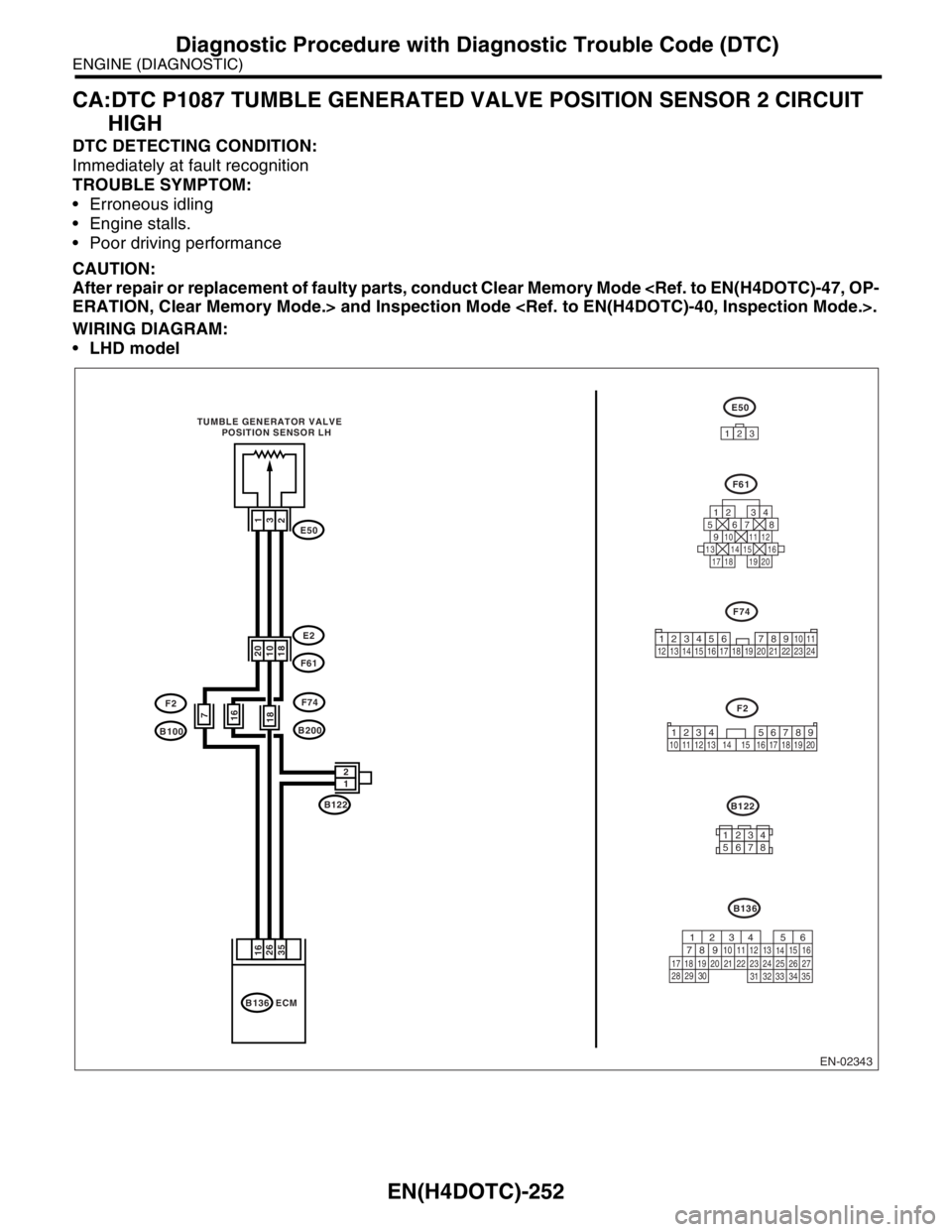
CA:DTC P1087 TUMBLE GENERATED VALVE POSITION SENSOR 2 CIRCUIT
HIGH
DTC DETECTING CONDITION:
Immediately at fault recognition
TROUBLE SYMPTOM:
Erroneous idling
Engine stalls.
Poor driving performance
CAUTION:
After repair or replacement of faulty parts, conduct Clear Memory Mode
WIRING DIAGRAM:
LHD model
EN-02343
E2
E50
F61
F74
B200
F2
B100
B122 TUMBLE GENERATOR VALVE
POSITION SENSOR LH
1
32
20
1018
1 2
B136 ECM
16
35 26
B136
E50
123
F61
F74
F2
125678
131415169101112
34
17181920
B122
34
12 8910 11
12 13 14 15 16 17 18 19 20 21 22 23 2456 7
1234 5678910 11 12 13 14 15 16 17 18 19 20
12345678
56
782 1
94 310
24 22 23 2511 12 13
1415
26 27
2816
17 18 19 20 21
33 34 29
32 30
31 35
187
16
Page 1886 of 2870
EN(H4DOTC)-253
ENGINE (DIAGNOSTIC)
Diagnostic Procedure with Diagnostic Trouble Code (DTC)
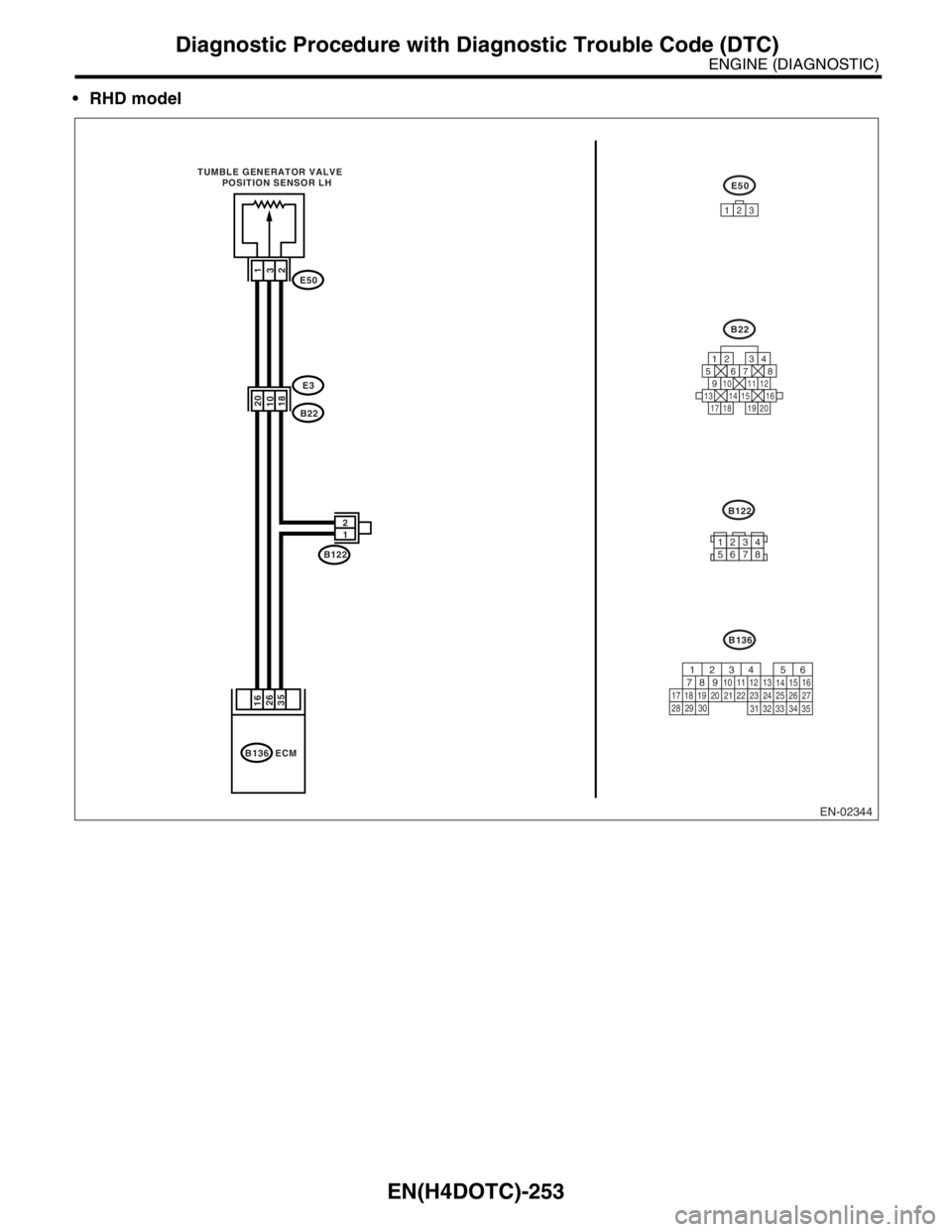
RHD model
EN-02344
E3
E50
B22
B122
1
32
20
1018
1 2
B136 ECM
16
35 26
B136
E50
123
B22
125678
131415169101112
34
17181920
B122 TUMBLE GENERATOR VALVE
POSITION SENSOR LH
56
782 1
94 310
24 22 23 2511 12 13
1415
26 27
2816
17 18 19 20 21
33 34 29
32 30
31 35
12345678
Page 1887 of 2870

EN(H4DOTC)-254
ENGINE (DIAGNOSTIC)
Diagnostic Procedure with Diagnostic Trouble Code (DTC)
Step Check Yes No
1 CHECK CURRENT DATA.
1) Start the engine.
2) Read the data of throttle position sensor
signal using Subaru Select Monitor or OBD-II
general scan tool.
N
OTE:
Subaru Select Monitor
For detailed operation procedure, refer to
“READ CURRENT DATA SHOWN ON DIS-
PLAY FOR ENGINE”.
OBD-II general scan tool
For detailed operation procedures, refer to the
OBD-II General Scan Tool Operation Manual.Is the voltage more than 4.9 V? Go to step 2.Even if the mal-
function indicator
light illuminates,
the circuit has
returned to a nor-
mal condition at
this time.A tempo-
rary poor contact
of the connector
may be the cause.
N
OTE:
In this case repair
the following:
Poor contact in
tumble generator
valve position sen-
sor connector
Poor contact in
ECM connector.
Poor contact in
coupling connector
2 CHECK HARNESS BETWEEN TUMBLE
GENERATOR VALVE POSITION SENSOR
AND ECM CONNECTOR.
1) Turn the ignition switch to OFF.
2) Disconnect the connectors from throttle
position sensor.
3) Measure the resistance of harness
between throttle position sensor connector and
engine ground.
Connector & terminal
(E50) No. 2 — Engine ground:Is the resistance less than 5
Ω?Go to step 3.Repair the har-
ness and connec-
tor.
N
OTE:
In this case repair
the following:
Open circuit in
harness between
tumble generator
valve position sen-
sor and ECM con-
nector
Poor contact in
coupling connector
Poor contact in
joint connector
3 CHECK HARNESS BETWEEN THROTTLE
POSITION SENSOR AND ECM CONNEC-
TOR.
1) Turn the ignition switch to ON.
2) Measure the voltage between throttle posi-
tion sensor connector and engine ground.
Connector & terminal
(E50) No. 3 (+) — Engine ground (
−):Is the voltage more than 4.9 V? Repair battery
short circuit in har-
ness between tum-
ble generator valve
position sensor
and ECM connec-
tor.After repair,
replace the ECM.
Engine Control
Module (ECM).>Replace the tum-
ble generator valve
assembly.
Tu m b l e G e n e r a t o r
Valve Assembly.>
Page 1888 of 2870
EN(H4DOTC)-255
ENGINE (DIAGNOSTIC)
Diagnostic Procedure with Diagnostic Trouble Code (DTC)
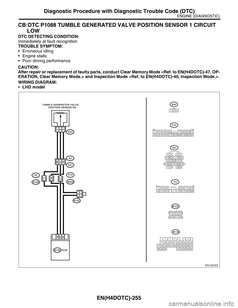
CB:DTC P1088 TUMBLE GENERATED VALVE POSITION SENSOR 1 CIRCUIT
LOW
DTC DETECTING CONDITION:
Immediately at fault recognition
TROUBLE SYMPTOM:
Erroneous idling
Engine stalls.
Poor driving performance
CAUTION:
After repair or replacement of faulty parts, conduct Clear Memory Mode
WIRING DIAGRAM:
LHD model
EN-02345
E54
F74
123
F61
125678
131415169101112
34
17181920
E2
E54
F61
F74
B200
F2
B100
B122 TUMBLE GENERATOR VALVE
POSITION SENSOR RH
1
32
20
918
1 2
B136 ECM
16
35 27
177
16
B136
F2
B122
1234 5678910 11 12 13 14 15 16 17 18 19 20
12345678
56
782 1
94 310
24 22 23 2511 12 13
1415
26 27
2816
17 18 19 20 21
33 34 29
32 30
31 35
34
12 8910 11
12 13 14 15 16 17 18 19 20 21 22 23 2456 7
Page 1889 of 2870
EN(H4DOTC)-256
ENGINE (DIAGNOSTIC)
Diagnostic Procedure with Diagnostic Trouble Code (DTC)
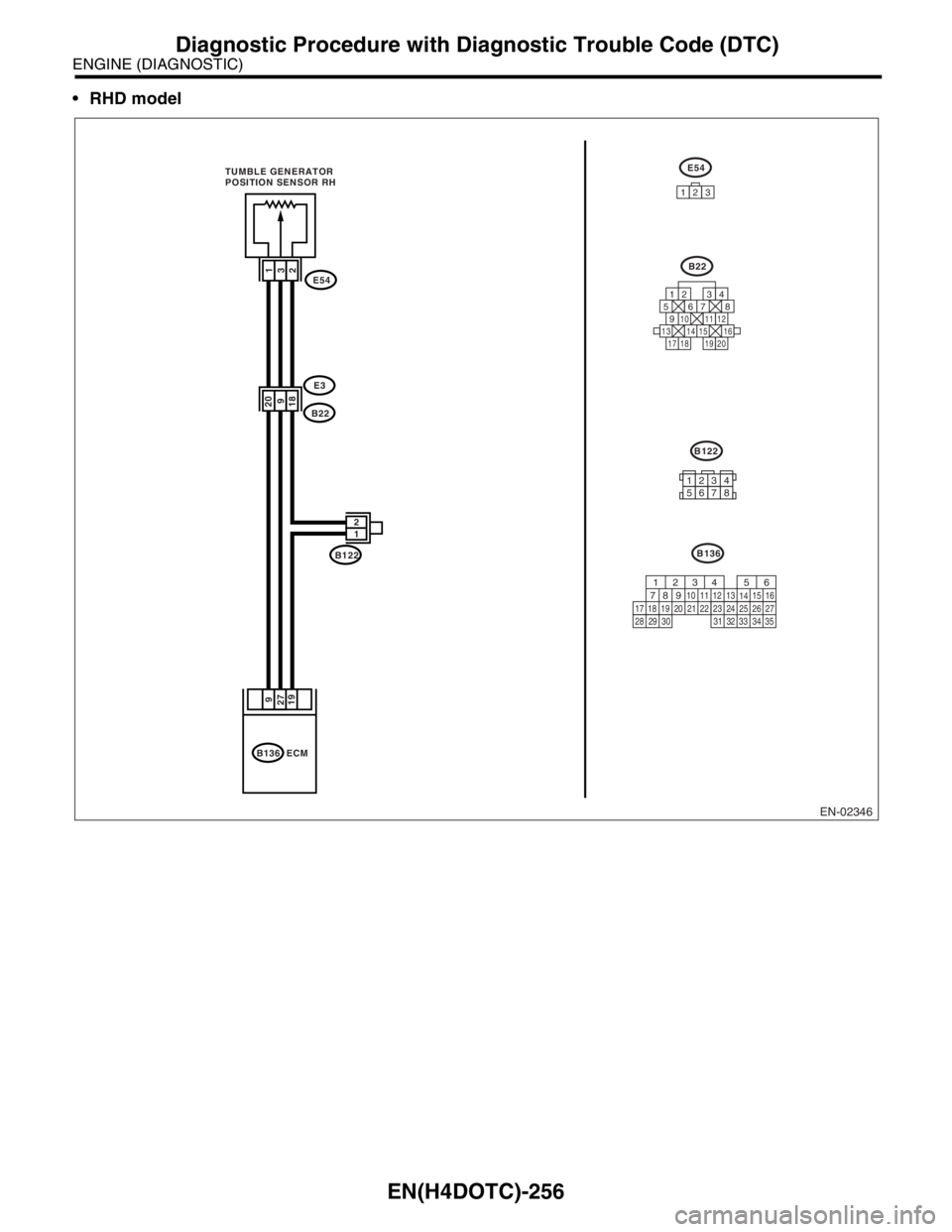
RHD model
EN-02346
E3
E54
B22
B122 TUMBLE GENERATOR
POSITION SENSOR RH
1
32
20
918
1 2
B136 ECM
9
19 27
E54
123
B22
125678
131415169101112
34
17181920
B136
B122
12345678
56
782 1
94 310
24 22 23 2511 12 13
1415
26 27
2816
17 18 19 20 21
33 34 29
32 30
31 35
Page 1890 of 2870

EN(H4DOTC)-257
ENGINE (DIAGNOSTIC)
Diagnostic Procedure with Diagnostic Trouble Code (DTC)
Step Check Yes No
1 CHECK CURRENT DATA.
1) Start the engine.
2) Read the data of tumble generator valve
position sensor signal using Subaru Select
Monitor or OBD-II general scan tool.
N
OTE:
Subaru Select Monitor
For detailed operation procedure, refer to
“READ CURRENT DATA SHOWN ON DIS-
PLAY FOR ENGINE”.
OBD-II general scan tool
For detailed operation procedures, refer to the
OBD-II General Scan Tool Operation Manual.Is the voltage less than 0.1 V? Go to step 2.Even if the mal-
function indicator
light illuminates,
the circuit has
returned to a nor-
mal condition at
this time.A tempo-
rary poor contact
of the connector
may be the cause.
N
OTE:
In this case repair
the following:
Poor contact in
tumble generator
valve position sen-
sor connector
Poor contact in
ECM connector.
Poor contact in
coupling connector
2 CHECK INPUT SIGNAL FROM ECM.
Measure the voltage between ECM connector
and chassis ground while throttle valve is fully
closed.
Connector & terminal
(B136) No. 16 (+) — Chassis ground (
−):Is the voltage more than 4.5 V? Go to step 4.Go to step 3.
3 CHECK INPUT SIGNAL FROM ECM.
Measure the voltage between ECM connector
and chassis ground.
Connector & terminal
(B136) No. 16 (+) — Chassis ground (
−):Does the voltage change by
shaking the harness and con-
nector of ECM while monitor-
ing the value with voltage
meter?Repair the poor
contact in ECM
connector.Contact the SUB-
ARU dealer.
N
OTE:
Inspection by DTM
is required, be-
cause probable
cause is deteriora-
tion of multiple
parts.
4 CHECK INPUT SIGNAL FROM ECM.
Measure the voltage between ECM connector
and chassis ground.
Connector & terminal
(B136) No. 27 (+) — Chassis ground (
−):Is the voltage less than 0.1 V? Go to step 6.Go to step 5.
5 CHECK INPUT SIGNAL FOR ECM (WITH
SUBARU SELECT MONITOR).
Measure the voltage between ECM connector
and chassis ground.Does the voltage change by
shaking the harness and con-
nector of ECM while monitor-
ing the value with Subaru
Select Monitor?Repair the poor
contact in ECM
connector.Go to step 6.