SUBARU FORESTER 2004 Service Repair Manual
Manufacturer: SUBARU, Model Year: 2004, Model line: FORESTER, Model: SUBARU FORESTER 2004Pages: 2870, PDF Size: 38.67 MB
Page 2311 of 2870

CS-26
CONTROL SYSTEM
General Diagnostic Table
8. General Diagnostic Table
A: INSPECTION
Symptom Possible cause Remedy
Select lever Starter does not run. Adjust the select cable and inhibitor switch, or
inspect the circuit.
Back-up light does not light up. Adjust the select cable and inhibitor switch, or
inspect the circuit.
Page 2312 of 2870
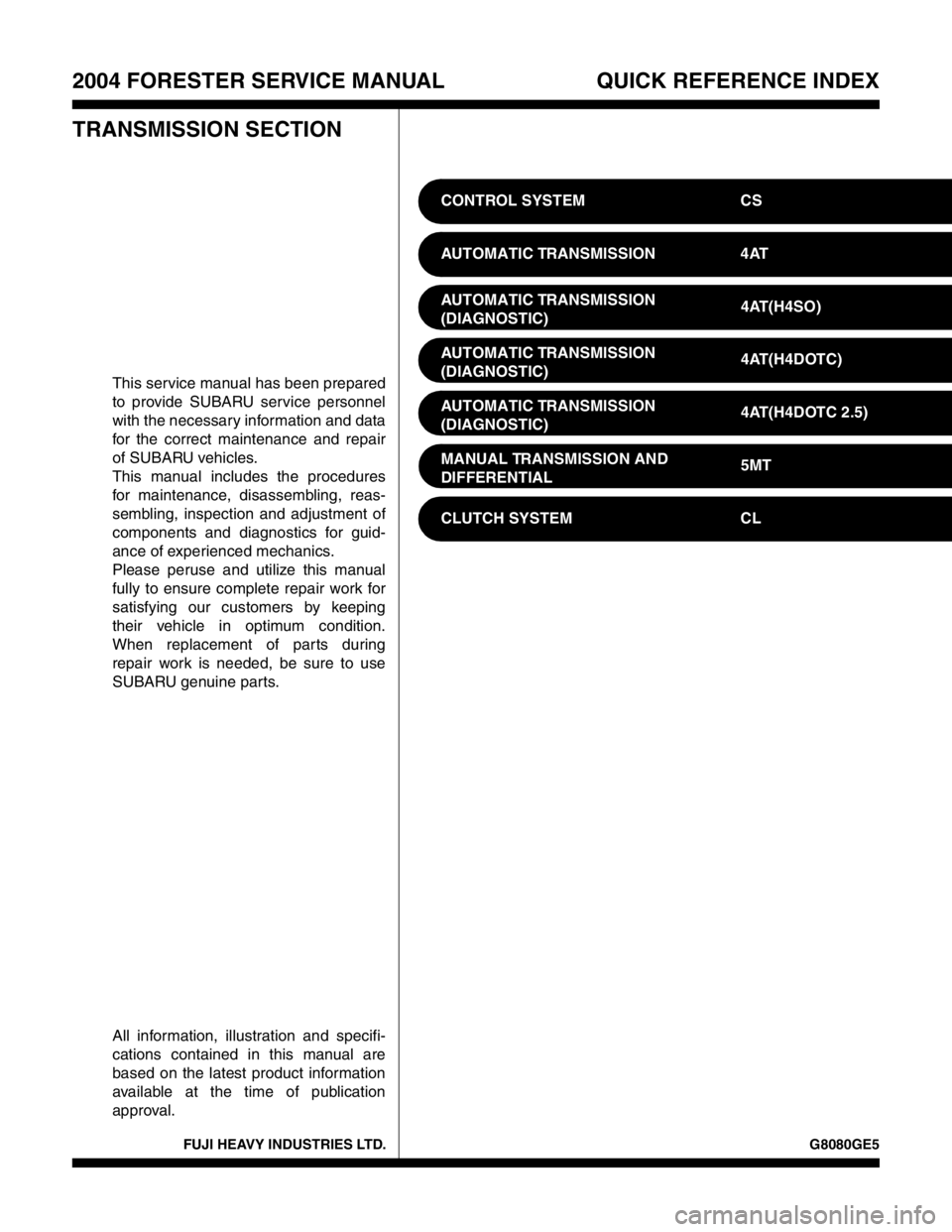
FUJI HEAVY INDUSTRIES LTD. G8080GE5
2004 FORESTER SERVICE MANUAL QUICK REFERENCE INDEX
TRANSMISSION SECTION
This service manual has been prepared
to provide SUBARU service personnel
with the necessary information and data
for the correct maintenance and repair
of SUBARU vehicles.
This manual includes the procedures
for maintenance, disassembling, reas-
sembling, inspection and adjustment of
components and diagnostics for guid-
ance of experienced mechanics.
Please peruse and utilize this manual
fully to ensure complete repair work for
satisfying our customers by keeping
their vehicle in optimum condition.
When replacement of parts during
repair work is needed, be sure to use
SUBARU genuine parts.
All information, illustration and specifi-
cations contained in this manual are
based on the latest product information
available at the time of publication
approval.CONTROL SYSTEM CS
AUTOMATIC TRANSMISSION 4AT
AUTOMATIC TRANSMISSION
(DIAGNOSTIC)4AT(H4SO)
AUTOMATIC TRANSMISSION
(DIAGNOSTIC)4AT(H4DOTC)
AUTOMATIC TRANSMISSION
(DIAGNOSTIC)4AT(H4DOTC 2.5)
MANUAL TRANSMISSION AND
DIFFERENTIAL5MT
CLUTCH SYSTEM CL
Page 2313 of 2870

AUTOMATIC TRANSMISSION
4AT
Page
1. General Description ....................................................................................2
2. Automatic Transmission Fluid ...................................................................30
3. Differential Gear Oil...................................................................................31
4. Road Test..................................................................................................32
5. Stall Test ...................................................................................................33
6. Time Lag Test ...........................................................................................35
7. Line Pressure Test ....................................................................................36
8. Transfer Clutch Pressure Test ..................................................................38
9. Automatic Transmission Assembly ...........................................................39
10. Transmission Mounting System ................................................................47
11. Extension Case Oil Seal ...........................................................................49
12. Differential Side Retainer Oil Seal.............................................................50
13. Inhibitor Switch ..........................................................................................51
14. Front Vehicle Speed Sensor .....................................................................55
15. Rear Vehicle Speed Sensor ......................................................................59
16. Torque Converter Turbine Speed Sensor .................................................60
17. Control Valve Body ...................................................................................61
18. Air Bleeding of Control Valve ....................................................................70
19.
Shift Solenoids, Duty Solenoids and ATF Temperature Sensor.........................71
20. Transfer Duty Solenoid and Valve Body ...................................................73
21. ATF Filter ..................................................................................................76
22. Transmission Control Module (TCM) ........................................................77
23. Dropping Resistor .....................................................................................78
24. ATF Cooler Pipe and Hose .......................................................................79
25. ATF Cooler (With Warmer Function).........................................................84
26. Air Breather Hose......................................................................................87
27. Oil Charger Pipe........................................................................................88
28. Torque Converter Clutch Assembly ..........................................................89
29. Extension Case .........................................................................................90
30. Transfer Clutch..........................................................................................92
31. Reduction Driven Gear..............................................................................97
32. Reduction Drive Gear................................................................................99
33. Parking Pawl ...........................................................................................101
34. Torque Converter Clutch Case ...............................................................102
35. Oil Pump Housing ...................................................................................105
36. Drive Pinion Shaft Assembly ...................................................................111
37. Front Differential......................................................................................117
38. AT Main Case .........................................................................................123
39. Transmission Control Device ..................................................................142
Page 2314 of 2870

4AT-2
AUTOMATIC TRANSMISSION
General Description
1. General Description
A: SPECIFICATION
1. TORQUE CONVERTER CLUTCH
2. OIL PUMP
3. TRANSMISSION CONTROL ELEMENT
4. TRANSMISSION GEAR RATIO5. PLANETARY GEAR AND PLATE
Model2.0 L
Non-
turbo2.5 L
Non-
turbo2.0 L
Tu r b o2.5 L
Tu r b o
Ty p eSymmetric, 3 element, single stage, 2 phase
torque converter
Stall torque
ratio2.0 —
2.21.9 —
2.11.85 —
2.152.05 —
2.35
Nominal
diameter246 mm (9.69 in)
Stall speed
(at sea level)2,000 —
2,500
rpm2,100 —
2,600
rpm2,600 —
3,300
rpm2,700 —
3,200
rpm
One-way
clutchSprague type one-way clutch
Type Pracoid constant-displacement pump
Driving method Driven by engine
Number of teethInner rotor 9
Outer rotor 10
Ty p e4-forward, 1-reverse, double-row plan-
etary gears
Multi-plate clutch 3 sets
Multi-plate brake 2 sets
One-way clutch
(sprague type)1 sets
Gear ratio
1st 2.785
2nd 1.545
3rd 1.000
4th 0.694
Rev 2.272
Model2.0 L Non-
turbo2.5 L Non-
turboTu r b o
Tooth num-
ber of front
sun gear33
Front pinion
number of
teeth21
Front inter-
nal gear
number of
teeth75
Tooth num-
ber of rear
sun gear42
Rear pinion
number of
teeth17
Tooth num-
ber of rear
internal gear75
Drive &
driven plate
number of
high clutch45
Drive &
driven plate
number of
low clutch467
Drive &
driven plate
number of
reverse
clutch2
Drive &
driven plate
number of 2-
4 brake34
Drive &
driven plate
number of
low &
reverse
brake467
Page 2315 of 2870

4AT-3
AUTOMATIC TRANSMISSION
General Description
6. SELECTOR POSITION
7. HYDRAULIC CONTROL AND LUBRICA-
TION
8. COOLING AND HARNESS9. TRANSFER
P (Park)Transmission in neutral, output member immov-
able, and engine start possible
R
(Reverse)Transmission in reverse
N (Neu-
tral)Transmission in neutral and engine start possi-
ble
D (Drive)Automatic gear change 1st
←
→ 2nd ←
→ 3rd ←
→
4th
3 (3rd)Automatic gear change 1st
←
→ 2nd ←
→ 3rd ←
4th
2 (2nd)Automatic gear change 1st
←
→ 2nd ← 3rd ←
4th
1 (1st)1st gear locked (Deceleration possible 1st ←
2nd ← 3rd ← 4th)
Control
methodWire cable type
Ty p eElectronic/hydraulic control
[Four forward speed
changes by electrical signals
of vehicle speed and accel-
erator (throttle) opening]
FluidDEXRON III type automatic
transmission fluid
Fluid capac-
ity2.0 L Non-
turbo model8.4 — 8.72 (8.9 — 9.2 US
qt, 7.4 — 7.7 Imp qt)
Except for
2.0 L Non-
turbo model9.3 — 9.62 (9.8 — 10.1 US
qt, 8.2 — 8.4 Imp qt)
Lubrication systemForced feed lubrication with
oil pump
OilAutomatic transmission fluid
(above mentioned)
Cooling SystemLiquid-cooled cooler incorpo-
rated in radiator
Inhibitor switch 12 poles
Transmission harness 20 poles
Model2.0 L Non-
turbo2.5 L Non-
turboTu r b o
Transfer
typeMulti-plate transfer (MPT)
Drive &
driven plate
number of
transfer
clutch456
Control
methodElectronic, hydraulic type
LubricantThe same Automatic transmission fluid used
in automatic transmission
Reduction
gear ratio1.000 (53/53)
Page 2316 of 2870
4AT-4
AUTOMATIC TRANSMISSION
General Description
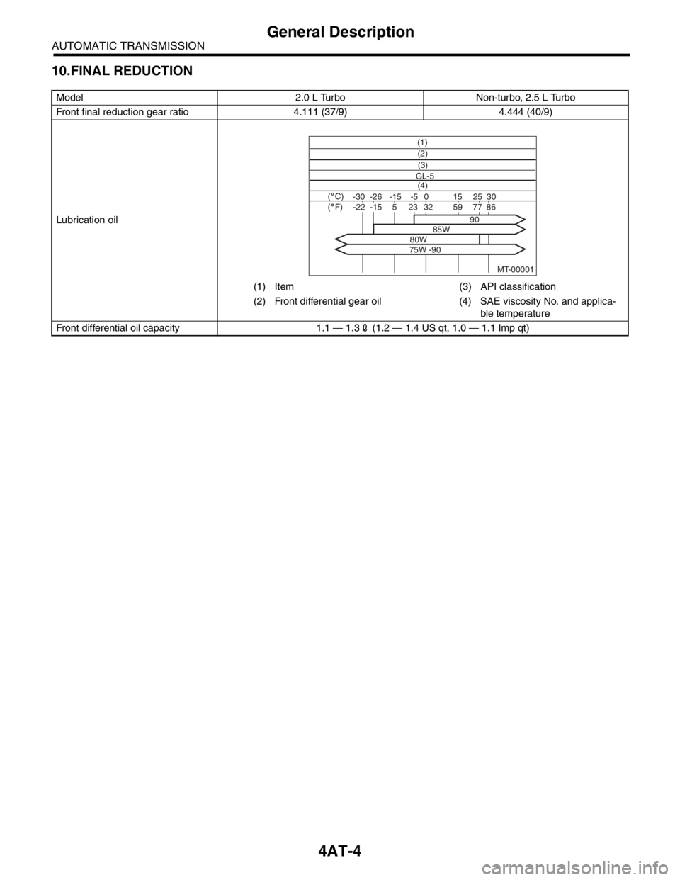
10.FINAL REDUCTION
Model 2.0 L Turbo Non-turbo, 2.5 L Turbo
Front final reduction gear ratio 4.111 (37/9) 4.444 (40/9)
Lubrication oil
(1) Item (3) API classification
(2) Front differential gear oil (4) SAE viscosity No. and applica-
ble temperature
Front differential oil capacity 1.1 — 1.32 (1.2 — 1.4 US qt, 1.0 — 1.1 Imp qt)
MT-00001
(1)
(4) GL-5(3) (2)
( C)( F)-30 -26 -15 15
90
85W
80W
75W -9025 30 -5 0-22-1523328659775
Page 2317 of 2870
4AT-5
AUTOMATIC TRANSMISSION
General Description
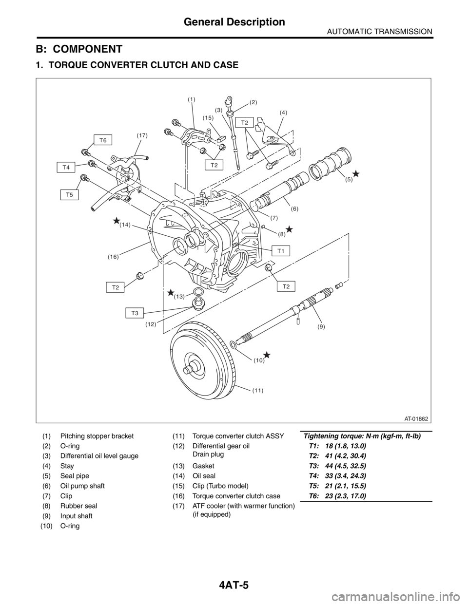
B: COMPONENT
1. TORQUE CONVERTER CLUTCH AND CASE
(1) Pitching stopper bracket (11) Torque converter clutch ASSYTightening torque: N⋅m (kgf-m, ft-lb)
(2) O-ring (12) Differential gear oil
Drain plugT1: 18 (1.8, 13.0)
(3) Differential oil level gaugeT2: 41 (4.2, 30.4)
(4) Stay (13) GasketT3: 44 (4.5, 32.5)
(5) Seal pipe (14) Oil sealT4: 33 (3.4, 24.3)
(6) Oil pump shaft (15) Clip (Turbo model)T5: 21 (2.1, 15.5)
(7) Clip (16) Torque converter clutch caseT6: 23 (2.3, 17.0)
(8) Rubber seal (17) ATF cooler (with warmer function)
(if equipped)
(9) Input shaft
(10) O-ring
AT-01862
T2
T2
T2T2
T3
T1
(8)
(11) (1)
(2)
(3)
(4)
(7)(5)
(6)
(10)(9)
(14)
(16)
(12)
(13)
(15)
T5 T4T6(17)
Page 2318 of 2870
4AT-6
AUTOMATIC TRANSMISSION
General Description
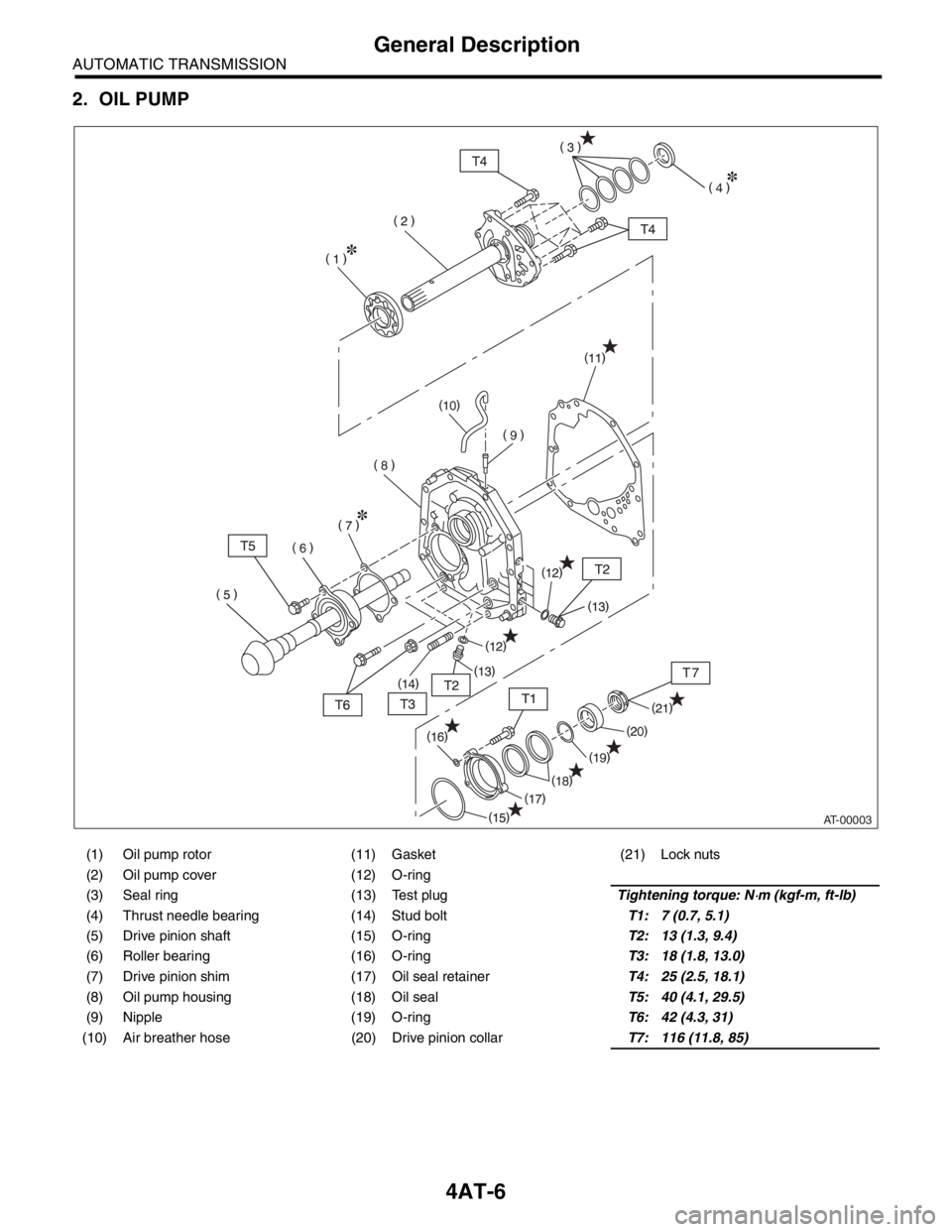
2. OIL PUMP
(1) Oil pump rotor (11) Gasket (21) Lock nuts
(2) Oil pump cover (12) O-ring
(3) Seal ring (13) Test plugTightening torque: N
⋅m (kgf-m, ft-lb)
(4) Thrust needle bearing (14) Stud boltT1: 7 (0.7, 5.1)
(5) Drive pinion shaft (15) O-ringT2: 13 (1.3, 9.4)
(6) Roller bearing (16) O-ringT3: 18 (1.8, 13.0)
(7) Drive pinion shim (17) Oil seal retainerT4: 25 (2.5, 18.1)
(8) Oil pump housing (18) Oil sealT5: 40 (4.1, 29.5)
(9) Nipple (19) O-ringT6: 42 (4.3, 31)
(10) Air breather hose (20) Drive pinion collarT7: 116 (11.8, 85)
AT-00003
Page 2319 of 2870
4AT-7
AUTOMATIC TRANSMISSION
General Description
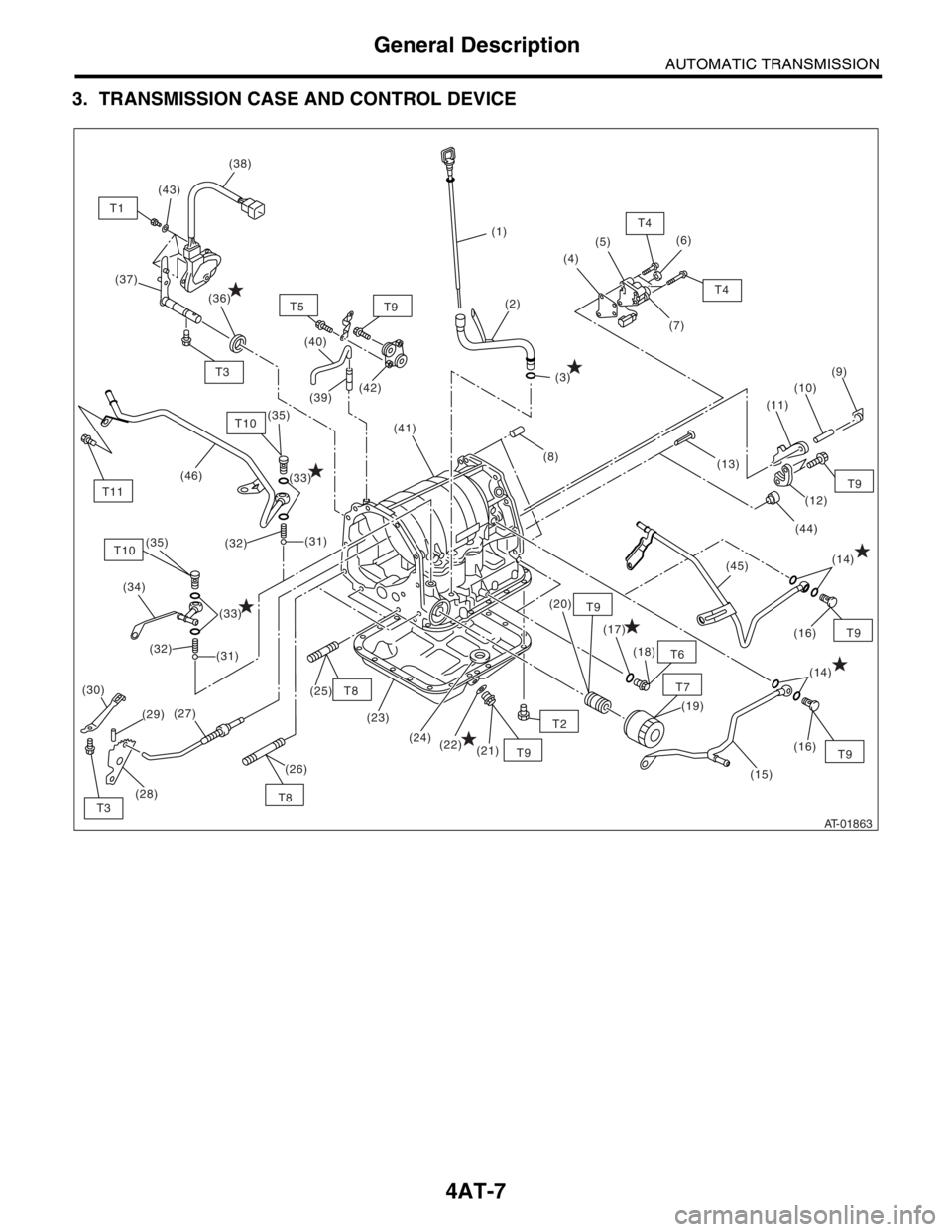
3. TRANSMISSION CASE AND CONTROL DEVICE
AT-01863
(1)
(2)
(3)(4)(5)(6)
(7)
(8)
(14)
(16) (17)
(18)
(19) (20)
(21) (22) (24) (23) (25)
(29) (34)(40)
(14)
(16)(9)
(10)
(11)
(12)
(44) (13)
(45)
(30)
(27)
(28)(26)
(15)
(32)
(31)
(33)
(33) (36) (37)
(35)(39)(42)
(41) (38)
(43)
T1
T4
T4
T6
T7 T9
T2
T9 T8
T9T9T9
T3T8T9 T5
T10T3
(32)(31)
(46)
(35)T10
T11
Page 2320 of 2870

4AT-8
AUTOMATIC TRANSMISSION
General Description
(1) ATF level gauge (19) Oil filter (41) Transmission case
(2) ATF charger pipe (20) Oil filter stud bolt (42) Plate ASSY
(3) O-ring (21) Drain plug (ATF) (43) Washer
(4) Transfer valve plate (22) Gasket (44) Bushing (turbo model)
(Non-turbo model) (23) Oil pan (45) ATF cooler inlet pipe (model with
ATF cooler (with warmer func-
tion)) (5) Transfer valve ASSY (24) Magnet
(Non-turbo model) (25) Stud bolt (Short)
(6) Transfer clutch seal
(Non-turbo model)(26) Stud bolt (Long) (46) ATF cooler outlet pipe (model
with ATF cooler (with warmer
function)) (27) Parking rod
(7) Transfer duty solenoid (non-turbo
model)(28) Manual plate
(29) Spring pin
(8) Straight pin (30) Detention springTightening torque: N
⋅m (kgf-m, ft-lb)
(9) Return spring (31) BallT1: 3.4 (0.35, 2.6)
(10) Shaft (32) SpringT2: 5 (0.5, 3.6)
(11) Parking pawl (33) GasketT3: 6 (0.6, 4.4)
(12) Parking support (34) ATF cooler outlet pipe (model
without ATF cooler (with warmer
function))T4: 8 (0.8, 6)
(13) Inlet filter (Non-turbo model)T5: 12 (1.2, 8.7)
(14) GasketT6: 13 (1.3, 10)
(15) ATF cooler inlet pipe (model with-
out ATF cooler (with warmer func-
tion))(35) Union screwT7: 14 (1.4, 10)
(36) Oil sealT8: 18 (1.8, 13)
(37) Range select leverT9: 25 (2.5, 18.1)
(16) Union screw (38) Inhibitor switch ASSYT10: 45 (4.6, 33.2)
(17) O-ring (39) NippleT11: 21 (2.1, 15.5)
(18) Test plug (40) Air breather hose