SUBARU FORESTER 2004 Service Repair Manual
Manufacturer: SUBARU, Model Year: 2004, Model line: FORESTER, Model: SUBARU FORESTER 2004Pages: 2870, PDF Size: 38.67 MB
Page 2741 of 2870
5MT-29
MANUAL TRANSMISSION AND DIFFERENTIAL
General Description
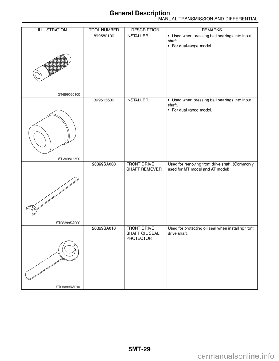
899580100 INSTALLER Used when pressing ball bearings into input
shaft.
For dual-range model.
399513600 INSTALLER Used when pressing ball bearings into input
shaft.
For dual-range model.
28399SA000 FRONT DRIVE
SHAFT REMOVERUsed for removing front drive shaft. (Commonly
used for MT model and AT model)
28399SA010 FRONT DRIVE
SHAFT OIL SEAL
PROTECTORUsed for protecting oil seal when installing front
drive shaft. ILLUSTRATION TOOL NUMBER DESCRIPTION REMARKS
ST-899580100
ST-399513600
ST28399SA000
ST28399SA010
Page 2742 of 2870

5MT-30
MANUAL TRANSMISSION AND DIFFERENTIAL
General Description
2. GENERAL TOOL
18675AA000 DIFFERENTIAL
SIDE OIL SEAL
INSTALLERUsed for installing differential side retainer oil
seal.
TOOL NAME REMARKS
Circuit tester Used for measuring resistance, voltage and ampere.ILLUSTRATION TOOL NUMBER DESCRIPTION REMARKS
ST18675AA000
Page 2743 of 2870
5MT-31
MANUAL TRANSMISSION AND DIFFERENTIAL
Transmission Gear Oil
2. Transmission Gear Oil
A: INSPECTION
1) Park the vehicle on a level surface.
2) Turn the ignition switch to OFF, and wait until the
engine cools.
3) Remove the oil level gauge and wipe it clean.
4) Reinsert the level gauge all the way. Be sure that
the level gauge is correctly inserted and in the
proper direction.
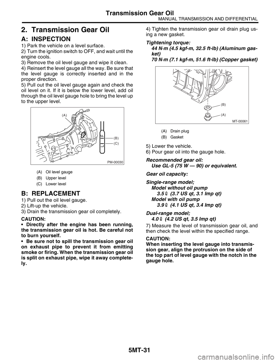
5) Pull out the oil level gauge again and check the
oil level on it. If it is below the lower level, add oil
through the oil level gauge hole to bring the level up
to the upper level.
B: REPLACEMENT
1) Pull out the oil level gauge.
2) Lift-up the vehicle.
3) Drain the transmission gear oil completely.
CAUTION:
Directly after the engine has been running,
the transmission gear oil is hot. Be careful not
to burn yourself.
Be sure not to spill the transmission gear oil
on exhaust pipe to prevent it from emitting
smoke or firing. When the transmission gear oil
is split on exhaust pipe, wipe it away complete-
ly.4) Tighten the transmission gear oil drain plug us-
ing a new gasket.
Tightening torque:
44 N·m (4.5 kgf-m, 32.5 ft-lb) (Aluminum gas-
ket)
70 N·m (7.1 kgf-m, 51.6 ft-lb) (Copper gasket)
5) Lower the vehicle.
6) Pour gear oil into the gauge hole.
Recommended gear oil:
Use GL-5 (75 W — 90) or equivalent.
Gear oil capacity:
Single-range model;
Model without oil pump
3.52 (3.7 US qt, 3.1 Imp qt)
Model with oil pump
3.92 (4.1 US qt, 3.4 Imp qt)
Dual-range model;
4.02 (4.2 US qt, 3.5 Imp qt)
7) Measure the level of transmission gear oil, and
then check the level within the specified range.
CAUTION:
When inserting the level gauge into transmis-
sion gear, align the protrusion on the side of
the top part of level gauge with the notch in the
gauge hole.
(A) Oil level gauge
(B) Upper level
(C) Lower level
PM-00030
(B)
(C) (A)
(A) Drain plug
(B) Gasket
MT-00061
(A) (B)
Page 2744 of 2870
5MT-32
MANUAL TRANSMISSION AND DIFFERENTIAL
Manual Transmission Assembly
3. Manual Transmission As-
sembly
A: REMOVAL
1) Set the vehicle on a lift.
2) Disconnect the ground cable from battery.
3) Drain the transmission gear oil completely.
Oil.>
4) Open the front hood fully, and support with stay.
5) Remove the air intake duct and air cleaner case.
(Non-turbo model)
6) Remove the air cleaner case stay. (Non-turbo
model)
7) Remove the intercooler. (Turbo model)
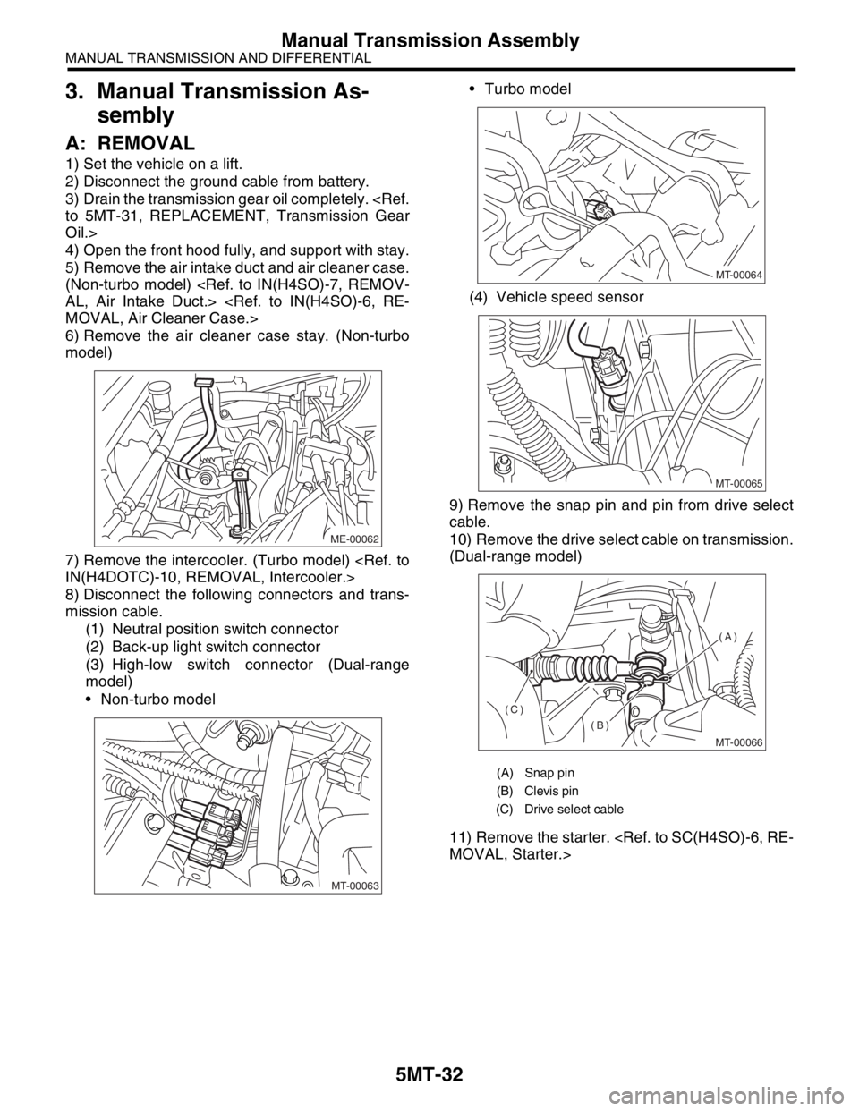
8) Disconnect the following connectors and trans-
mission cable.
(1) Neutral position switch connector
(2) Back-up light switch connector
(3) High-low switch connector (Dual-range
model)
Non-turbo model Turbo model
(4) Vehicle speed sensor
9) Remove the snap pin and pin from drive select
cable.
10) Remove the drive select cable on transmission.
(Dual-range model)
11) Remove the starter.
ME-00062
MT-00063
(A) Snap pin
(B) Clevis pin
(C) Drive select cable
MT-00064
MT-00065
MT-00066
(A)
(B)
(C)
Page 2745 of 2870
5MT-33
MANUAL TRANSMISSION AND DIFFERENTIAL
Manual Transmission Assembly
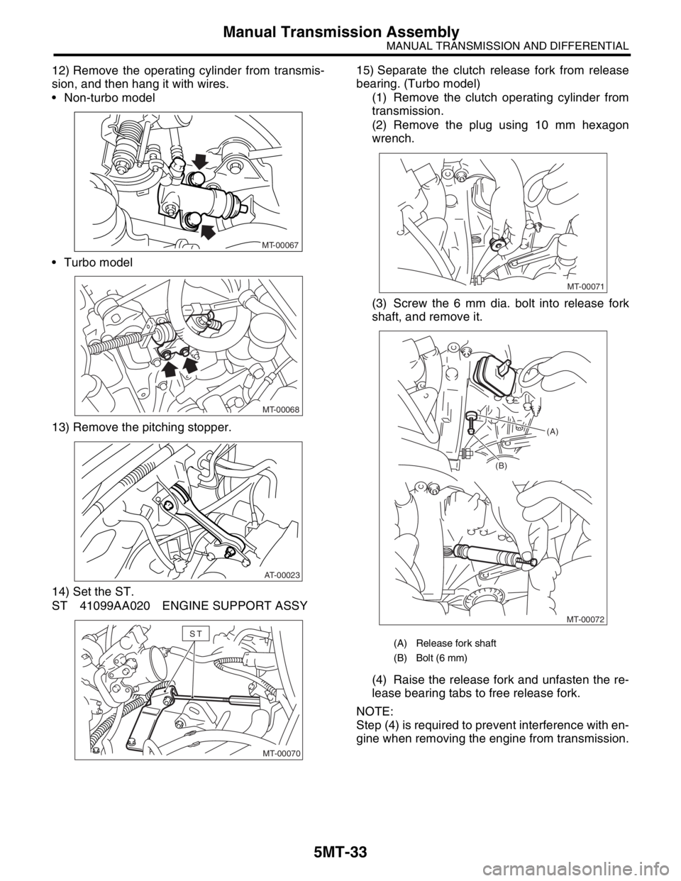
12) Remove the operating cylinder from transmis-
sion, and then hang it with wires.
Non-turbo model
Turbo model
13) Remove the pitching stopper.
14) Set the ST.
ST 41099AA020 ENGINE SUPPORT ASSY15) Separate the clutch release fork from release
bearing. (Turbo model)
(1) Remove the clutch operating cylinder from
transmission.
(2) Remove the plug using 10 mm hexagon
wrench.
(3) Screw the 6 mm dia. bolt into release fork
shaft, and remove it.
(4) Raise the release fork and unfasten the re-
lease bearing tabs to free release fork.
NOTE:
Step (4) is required to prevent interference with en-
gine when removing the engine from transmission.
MT-00067
MT-00068
AT-00023
MT-00070
ST(A) Release fork shaft
(B) Bolt (6 mm)
MT-00071
MT-00072 (B)(A)
Page 2746 of 2870
5MT-34
MANUAL TRANSMISSION AND DIFFERENTIAL
Manual Transmission Assembly
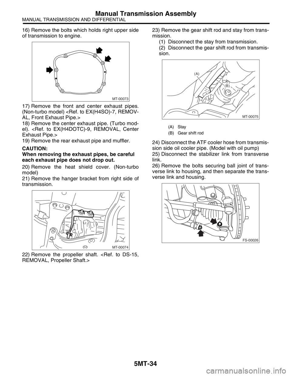
16) Remove the bolts which holds right upper side
of transmission to engine.
17) Remove the front and center exhaust pipes.
(Non-turbo model)
18) Remove the center exhaust pipe. (Turbo mod-
el).
19) Remove the rear exhaust pipe and muffler.
CAUTION:
When removing the exhaust pipes, be careful
each exhaust pipe does not drop out.
20) Remove the heat shield cover. (Non-turbo
model)
21) Remove the hanger bracket from right side of
transmission.
22) Remove the propeller shaft.
mission.
(1) Disconnect the stay from transmission.
(2) Disconnect the gear shift rod from transmis-
sion.
24) Disconnect the ATF cooler hose from transmis-
sion side oil cooler pipe. (Model with oil pump)
25) Disconnect the stabilizer link from transverse
link.
26) Remove the bolts securing ball joint of trans-
verse link to housing, and then separate the trans-
verse link and housing.
MT-00073
MT-00074
(A) Stay
(B) Gear shift rod
MT-00075
(A)
(B)
(B)
FS-00026
Page 2747 of 2870
5MT-35
MANUAL TRANSMISSION AND DIFFERENTIAL
Manual Transmission Assembly
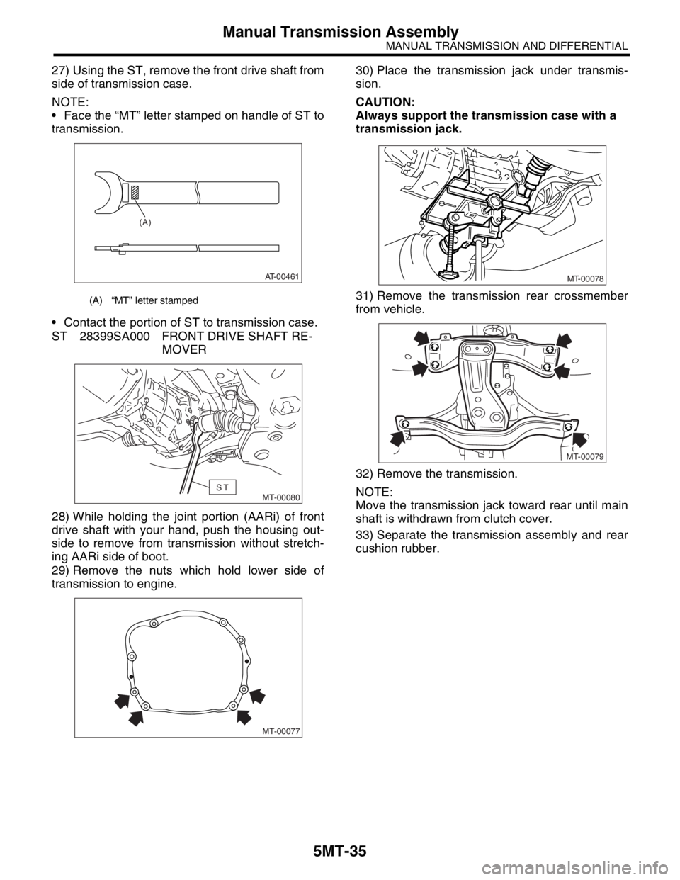
27) Using the ST, remove the front drive shaft from
side of transmission case.
NOTE:
Face the “MT” letter stamped on handle of ST to
transmission.
Contact the portion of ST to transmission case.
ST 28399SA000 FRONT DRIVE SHAFT RE-
MOVER
28) While holding the joint portion (AARi) of front
drive shaft with your hand, push the housing out-
side to remove from transmission without stretch-
ing AARi side of boot.
29) Remove the nuts which hold lower side of
transmission to engine.30) Place the transmission jack under transmis-
sion.
CAUTION:
Always support the transmission case with a
transmission jack.
31) Remove the transmission rear crossmember
from vehicle.
32) Remove the transmission.
NOTE:
Move the transmission jack toward rear until main
shaft is withdrawn from clutch cover.
33) Separate the transmission assembly and rear
cushion rubber.
(A) “MT” letter stamped
AT-00461
(A)
MT-00080ST
MT-00077
MT-00078
MT-00079
Page 2748 of 2870
5MT-36
MANUAL TRANSMISSION AND DIFFERENTIAL
Manual Transmission Assembly
B: INSTALLATION
1) Replace the differential side retainer oil seal with
a new one.
NOTE:
When pulling out the front drive shaft, always re-
place the differential side retainer oil seal.
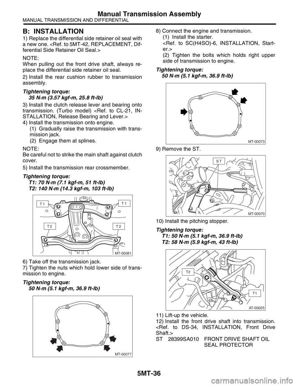
2) Install the rear cushion rubber to transmission
assembly.
Tightening torque:
35 N·m (3.57 kgf-m, 25.8 ft-lb)
3) Install the clutch release lever and bearing onto
transmission. (Turbo model)
4) Install the transmission onto engine.
(1) Gradually raise the transmission with trans-
mission jack.
(2) Engage them at splines.
NOTE:
Be careful not to strike the main shaft against clutch
cover.
5) Install the transmission rear crossmember.
Tightening torque:
T1: 70 N·m (7.1 kgf-m, 51 ft-lb)
T2: 140 N·m (14.3 kgf-m, 103 ft-lb)
6) Take off the transmission jack.
7) Tighten the nuts which hold lower side of trans-
mission to engine.
Tightening torque:
50 N·m (5.1 kgf-m, 36.9 ft-lb)8) Connect the engine and transmission.
(1) Install the starter.
(2) Tighten the bolts which holds right upper
side of transmission to engine.
Tightening torque:
50 N·m (5.1 kgf-m, 36.9 ft-lb)
9) Remove the ST.
10) Install the pitching stopper.
Tightening torque:
T1: 50 N·m (5.1 kgf-m, 36.9 ft-lb)
T2: 58 N·m (5.9 kgf-m, 43 ft-lb)
11) Lift-up the vehicle.
12) Install the front drive shaft into transmission.
ST 28399SA010 FRONT DRIVE SHAFT OIL
SEAL PROTECTOR
MT-00081
T2T2
T1T1
MT-00077
MT-00073
MT-00070
ST
AT-00025
T1
T2
Page 2749 of 2870
5MT-37
MANUAL TRANSMISSION AND DIFFERENTIAL
Manual Transmission Assembly
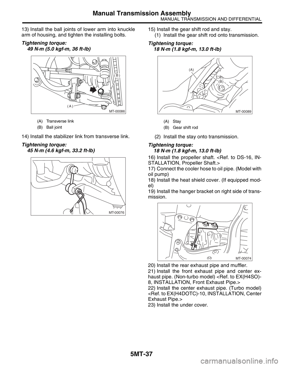
13) Install the ball joints of lower arm into knuckle
arm of housing, and tighten the installing bolts.
Tightening torque:
49 N·m (5.0 kgf-m, 36 ft-lb)
14) Install the stabilizer link from transverse link.
Tightening torque:
45 N·m (4.6 kgf-m, 33.2 ft-lb)15) Install the gear shift rod and stay.
(1) Install the gear shift rod onto transmission.
Tightening torque:
18 N·m (1.8 kgf-m, 13.0 ft-lb)
(2) Install the stay onto transmission.
Tightening torque:
18 N·m (1.8 kgf-m, 13.0 ft-lb)
16) Install the propeller shaft.
17) Connect the cooler hose to oil pipe. (Model with
oil pump)
18) Install the heat shield cover. (If equipped mod-
el)
19) Install the hanger bracket on right side of trans-
mission.
20) Install the rear exhaust pipe and muffler.
21) Install the front exhaust pipe and center ex-
haust pipe. (Non-turbo model)
22) Install the center exhaust pipe. (Turbo model)
23) Install the under cover.
(A) Transverse link
(B) Ball joint
MT-00086
(A)
(B)
MT-00076
(A) Stay
(B) Gear shift rod
MT-00089
(A)
(B)
(B)
MT-00074
Page 2750 of 2870
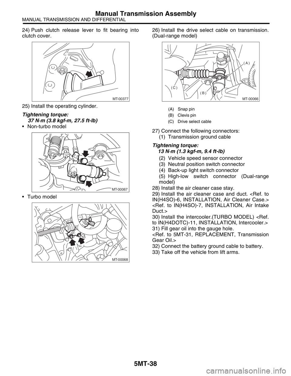
5MT-38
MANUAL TRANSMISSION AND DIFFERENTIAL
Manual Transmission Assembly
24) Push clutch release lever to fit bearing into
clutch cover.
25) Install the operating cylinder.
Tightening torque:
37 N·m (3.8 kgf-m, 27.5 ft-lb)
Non-turbo model
Turbo model26) Install the drive select cable on transmission.
(Dual-range model)
27) Connect the following connectors:
(1) Transmission ground cable
Tightening torque:
13 N·m (1.3 kgf-m, 9.4 ft-lb)
(2) Vehicle speed sensor connector
(3) Neutral position switch connector
(4) Back-up light switch connector
(5) High-low switch connector (Dual-range
model)
28) Install the air cleaner case stay.
29) Install the air cleaner case and duct.
30) Install the intercooler.(TURBO MODEL)
31) Fill gear oil into the gauge hole.
32) Connect the battery ground cable to battery.
33) Take off the vehicle from lift arms.
MT-00377
MT-00067
MT-00068
(A) Snap pin
(B) Clevis pin
(C) Drive select cable
MT-00066
(A)
(B)
(C)