SUBARU FORESTER 2004 Service Repair Manual
Manufacturer: SUBARU, Model Year: 2004, Model line: FORESTER, Model: SUBARU FORESTER 2004Pages: 2870, PDF Size: 38.67 MB
Page 2841 of 2870
CL-15
CLUTCH SYSTEM
General Description
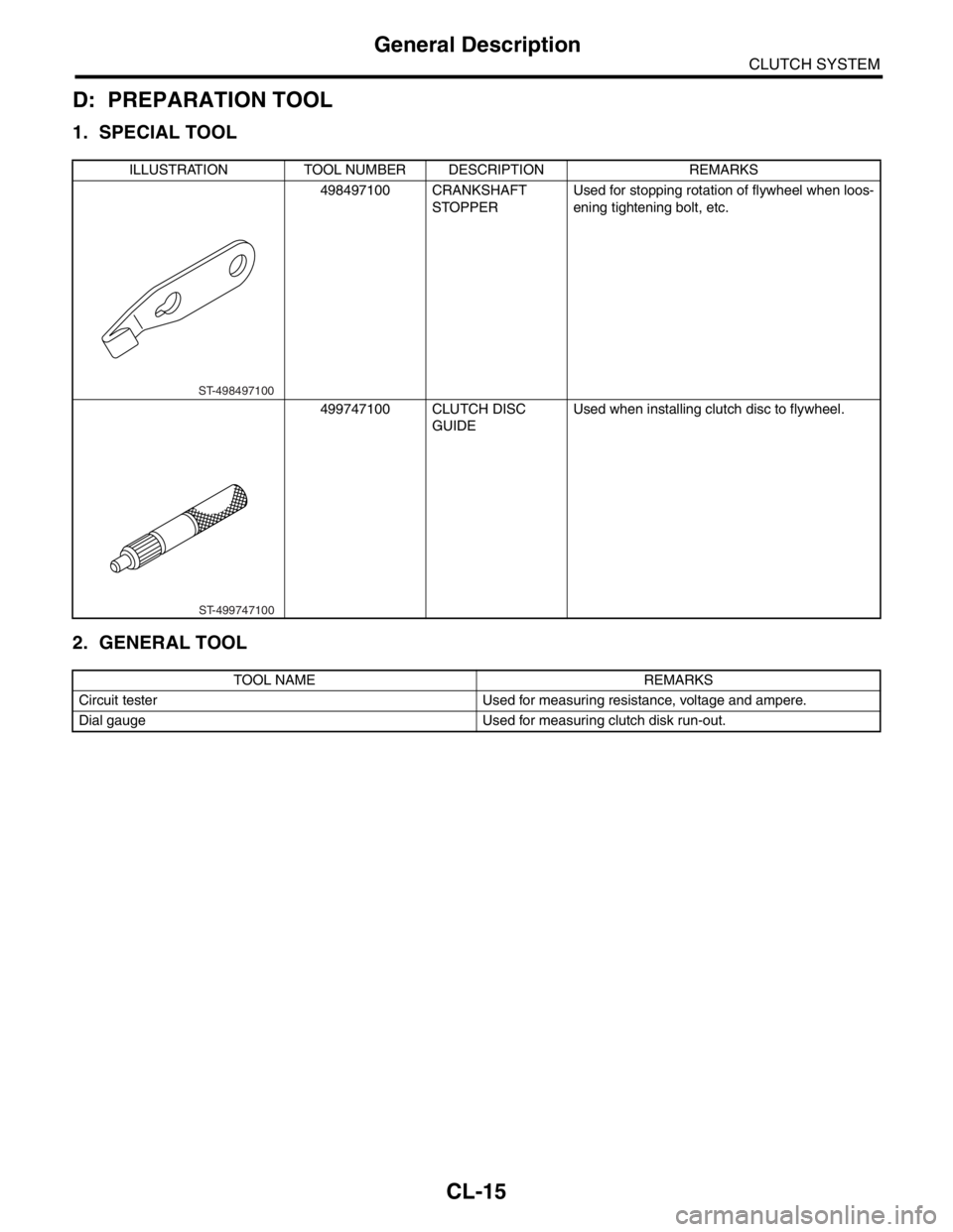
D: PREPARATION TOOL
1. SPECIAL TOOL
2. GENERAL TOOL
ILLUSTRATION TOOL NUMBER DESCRIPTION REMARKS
498497100 CRANKSHAFT
STOPPER Used for stopping rotation of flywheel when loos-
ening tightening bolt, etc.
499747100 CLUTCH DISC
GUIDEUsed when installing clutch disc to flywheel.
TOOL NAME REMARKS
Circuit tester Used for measuring resistance, voltage and ampere.
Dial gauge Used for measuring clutch disk run-out.
ST-498497100
ST-499747100
Page 2842 of 2870
CL-16
CLUTCH SYSTEM
Clutch Disc and Cover
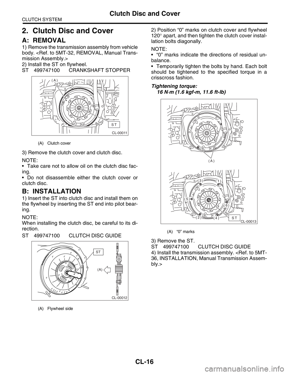
2. Clutch Disc and Cover
A: REMOVAL
1) Remove the transmission assembly from vehicle
body.
2) Install the ST on flywheel.
ST 499747100 CRANKSHAFT STOPPER
3) Remove the clutch cover and clutch disc.
NOTE:
Take care not to allow oil on the clutch disc fac-
ing.
Do not disassemble either the clutch cover or
clutch disc.
B: INSTALLATION
1) Insert the ST into clutch disc and install them on
the flywheel by inserting the ST end into pilot bear-
ing.
NOTE:
When installing the clutch disc, be careful to its di-
rection.
ST 499747100 CLUTCH DISC GUIDE2) Position “0” marks on clutch cover and flywheel
120° apart, and then tighten the clutch cover instal-
lation bolts diagonally.
NOTE:
“0” marks indicate the directions of residual un-
balance.
Temporarily tighten the bolts by hand. Each bolt
should be tightened to the specified torque in a
crisscross fashion.
Tightening torque:
16 N
⋅m (1.6 kgf-m, 11.6 ft-lb)
3) Remove the ST.
ST 499747100 CLUTCH DISC GUIDE
4) Install the transmission assembly.
bly.>
(A) Clutch cover
(A) Flywheel side
CL-00011
(A)
ST
CL-00012
(A)
ST
(A) “0” marks
CL-00013 (A)ST(2)
(5)
(3)(1)
(6)
(4)
Page 2843 of 2870
CL-17
CLUTCH SYSTEM
Clutch Disc and Cover
C: INSPECTION
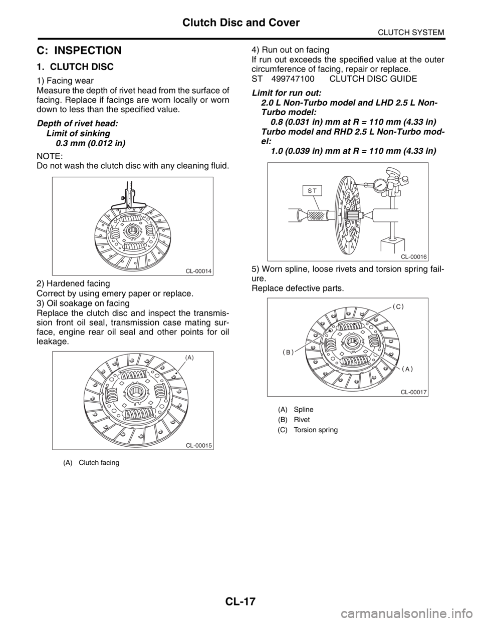
1. CLUTCH DISC
1) Facing wear
Measure the depth of rivet head from the surface of
facing. Replace if facings are worn locally or worn
down to less than the specified value.
Depth of rivet head:
Limit of sinking
0.3 mm (0.012 in)
NOTE:
Do not wash the clutch disc with any cleaning fluid.
2) Hardened facing
Correct by using emery paper or replace.
3) Oil soakage on facing
Replace the clutch disc and inspect the transmis-
sion front oil seal, transmission case mating sur-
face, engine rear oil seal and other points for oil
leakage.4) Run out on facing
If run out exceeds the specified value at the outer
circumference of facing, repair or replace.
ST 499747100 CLUTCH DISC GUIDE
Limit for run out:
2.0 L Non-Turbo model and LHD 2.5 L Non-
Turbo model:
0.8 (0.031 in) mm at R = 110 mm (4.33 in)
Turbo model and RHD 2.5 L Non-Turbo mod-
el:
1.0 (0.039 in) mm at R = 110 mm (4.33 in)
5) Worn spline, loose rivets and torsion spring fail-
ure.
Replace defective parts.
(A) Clutch facing
CL-00014
CL-00015
(A)
(A) Spline
(B) Rivet
(C) Torsion spring
CL-00016
ST
CL-00017
Page 2844 of 2870
CL-18
CLUTCH SYSTEM
Clutch Disc and Cover
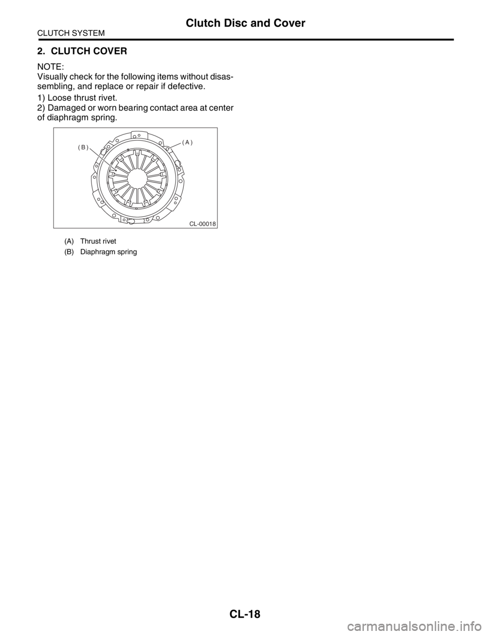
2. CLUTCH COVER
NOTE:
Visually check for the following items without disas-
sembling, and replace or repair if defective.
1) Loose thrust rivet.
2) Damaged or worn bearing contact area at center
of diaphragm spring.
(A) Thrust rivet
(B) Diaphragm spring
CL-00018
(A)
(B)
Page 2845 of 2870
CL-19
CLUTCH SYSTEM
Flywheel
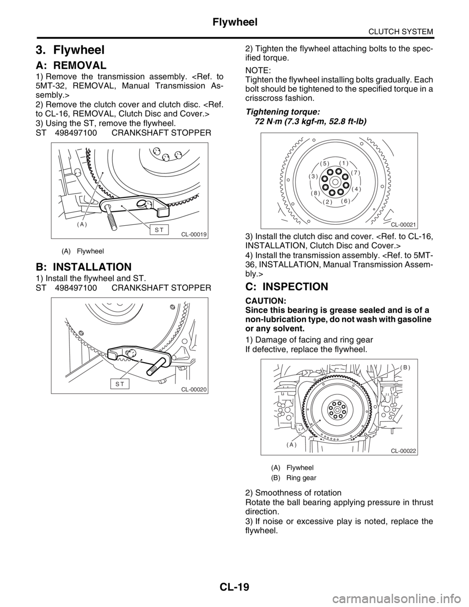
3. Flywheel
A: REMOVAL
1) Remove the transmission assembly.
sembly.>
2) Remove the clutch cover and clutch disc.
3) Using the ST, remove the flywheel.
ST 498497100 CRANKSHAFT STOPPER
B: INSTALLATION
1) Install the flywheel and ST.
ST 498497100 CRANKSHAFT STOPPER2) Tighten the flywheel attaching bolts to the spec-
ified torque.
NOTE:
Tighten the flywheel installing bolts gradually. Each
bolt should be tightened to the specified torque in a
crisscross fashion.
Tightening torque:
72 N
⋅m (7.3 kgf-m, 52.8 ft-lb)
3) Install the clutch disc and cover.
4) Install the transmission assembly.
bly.>
C: INSPECTION
CAUTION:
Since this bearing is grease sealed and is of a
non-lubrication type, do not wash with gasoline
or any solvent.
1) Damage of facing and ring gear
If defective, replace the flywheel.
2) Smoothness of rotation
Rotate the ball bearing applying pressure in thrust
direction.
3) If noise or excessive play is noted, replace the
flywheel.
(A) Flywheel
CL-00019ST (A)
CL-00020ST
(A) Flywheel
(B) Ring gear
CL-00021
(1)
(2)
(3)
(4)
(5)
(6)
(7)
(8)
CL-00022
(B)
(A)
Page 2846 of 2870
CL-20
CLUTCH SYSTEM
Release Bearing and Lever
4. Release Bearing and Lever
A: REMOVAL
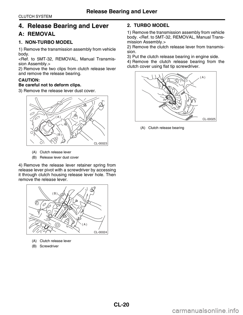
1. NON-TURBO MODEL
1) Remove the transmission assembly from vehicle
body.
2) Remove the two clips from clutch release lever
and remove the release bearing.
CAUTION:
Be careful not to deform clips.
3) Remove the release lever dust cover.
4) Remove the release lever retainer spring from
release lever pivot with a screwdriver by accessing
it through clutch housing release lever hole. Then
remove the release lever.
2. TURBO MODEL
1) Remove the transmission assembly from vehicle
body.
2) Remove the clutch release lever from transmis-
sion.
3) Put the clutch release bearing in engine side.
4) Remove the clutch release bearing from the
clutch cover using flat tip screwdriver.
(A) Clutch release lever
(B) Release lever dust cover
(A) Clutch release lever
(B) Screwdriver
CL-00023
(A)
(B)
CL-00024
(B)
(A)
(A) Clutch release bearing
CL-00025
(A)
Page 2847 of 2870
CL-21
CLUTCH SYSTEM
Release Bearing and Lever
B: INSTALLATION
1. NON-TURBO MODEL
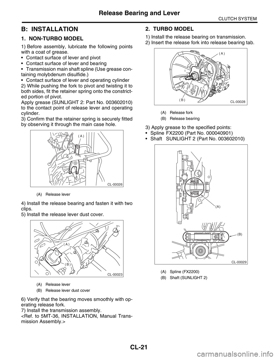
1) Before assembly, lubricate the following points
with a coat of grease.
Contact surface of lever and pivot
Contact surface of lever and bearing
Transmission main shaft spline (Use grease con-
taining molybdenum disulfide.)
Contact surface of lever and operating cylinder
2) While pushing the fork to pivot and twisting it to
both sides, fit the retainer spring onto the constrict-
ed portion of pivot.
Apply grease (SUNLIGHT 2: Part No. 003602010)
to the contact point of release lever and operating
cylinder.
3) Confirm that the retainer spring is securely fitted
by observing it through the main case hole.
4) Install the release bearing and fasten it with two
clips.
5) Install the release lever dust cover.
6) Verify that the bearing moves smoothly with op-
erating release fork.
7) Install the transmission assembly.
2. TURBO MODEL
1) Install the release bearing on transmission.
2) Insert the release fork into release bearing tab.
3) Apply grease to the specified points:
Spline FX2200 (Part No. 000040901)
Shaft SUNLIGHT 2 (Part No. 003602010)
(A) Release lever
(A) Release lever
(B) Release lever dust cover
CL-00026
(A)
CL-00023
(A)
(B)
(A) Release fork
(B) Release bearing
(A) Spline (FX2200)
(B) Shaft (SUNLIGHT 2)
CL-00028
(A)
(B)
CL-00029 (A)
(B)
Page 2848 of 2870
CL-22
CLUTCH SYSTEM
Release Bearing and Lever
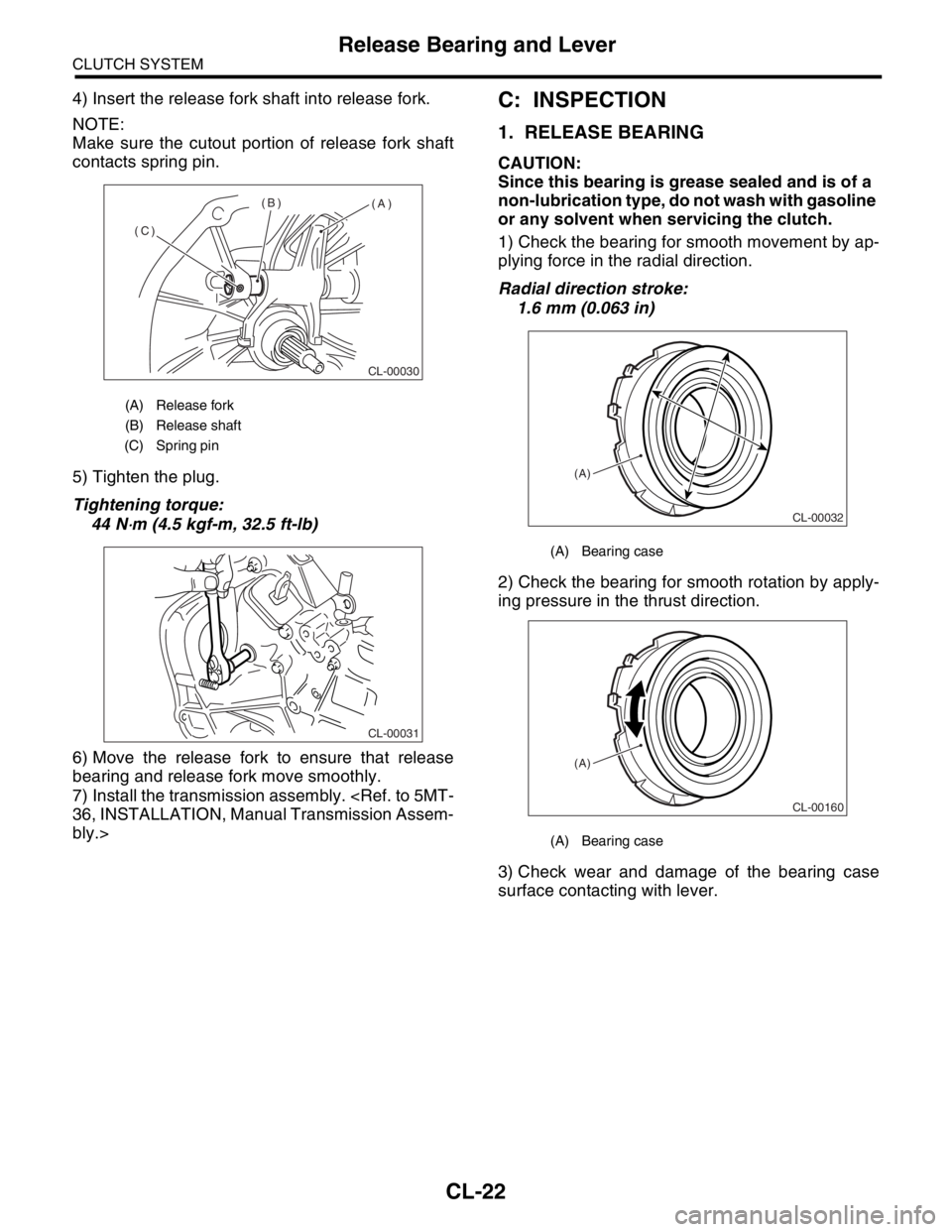
4) Insert the release fork shaft into release fork.
NOTE:
Make sure the cutout portion of release fork shaft
contacts spring pin.
5) Tighten the plug.
Tightening torque:
44 N
⋅m (4.5 kgf-m, 32.5 ft-lb)
6) Move the release fork to ensure that release
bearing and release fork move smoothly.
7) Install the transmission assembly.
bly.>
C: INSPECTION
1. RELEASE BEARING
CAUTION:
Since this bearing is grease sealed and is of a
non-lubrication type, do not wash with gasoline
or any solvent when servicing the clutch.
1) Check the bearing for smooth movement by ap-
plying force in the radial direction.
Radial direction stroke:
1.6 mm (0.063 in)
2) Check the bearing for smooth rotation by apply-
ing pressure in the thrust direction.
3) Check wear and damage of the bearing case
surface contacting with lever.
(A) Release fork
(B) Release shaft
(C) Spring pin
CL-00030
(A) (B)
(C)
CL-00031
(A) Bearing case
(A) Bearing case
CL-00032
(A)
CL-00160
(A)
Page 2849 of 2870
CL-23
CLUTCH SYSTEM
Release Bearing and Lever
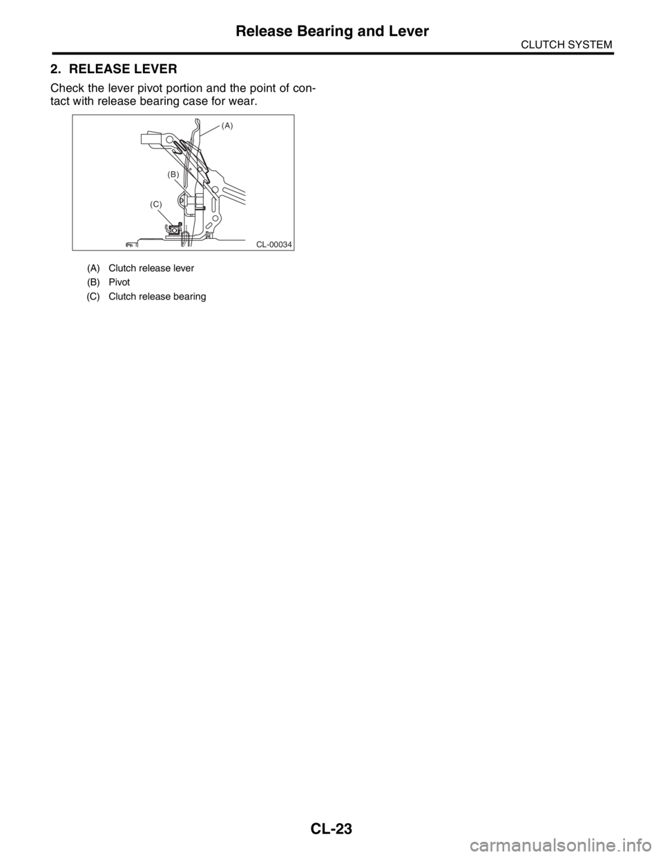
2. RELEASE LEVER
Check the lever pivot portion and the point of con-
tact with release bearing case for wear.
(A) Clutch release lever
(B) Pivot
(C) Clutch release bearing
CL-00034
(A)
(B)
(C)
Page 2850 of 2870
CL-24
CLUTCH SYSTEM
Operating Cylinder
5. Operating Cylinder
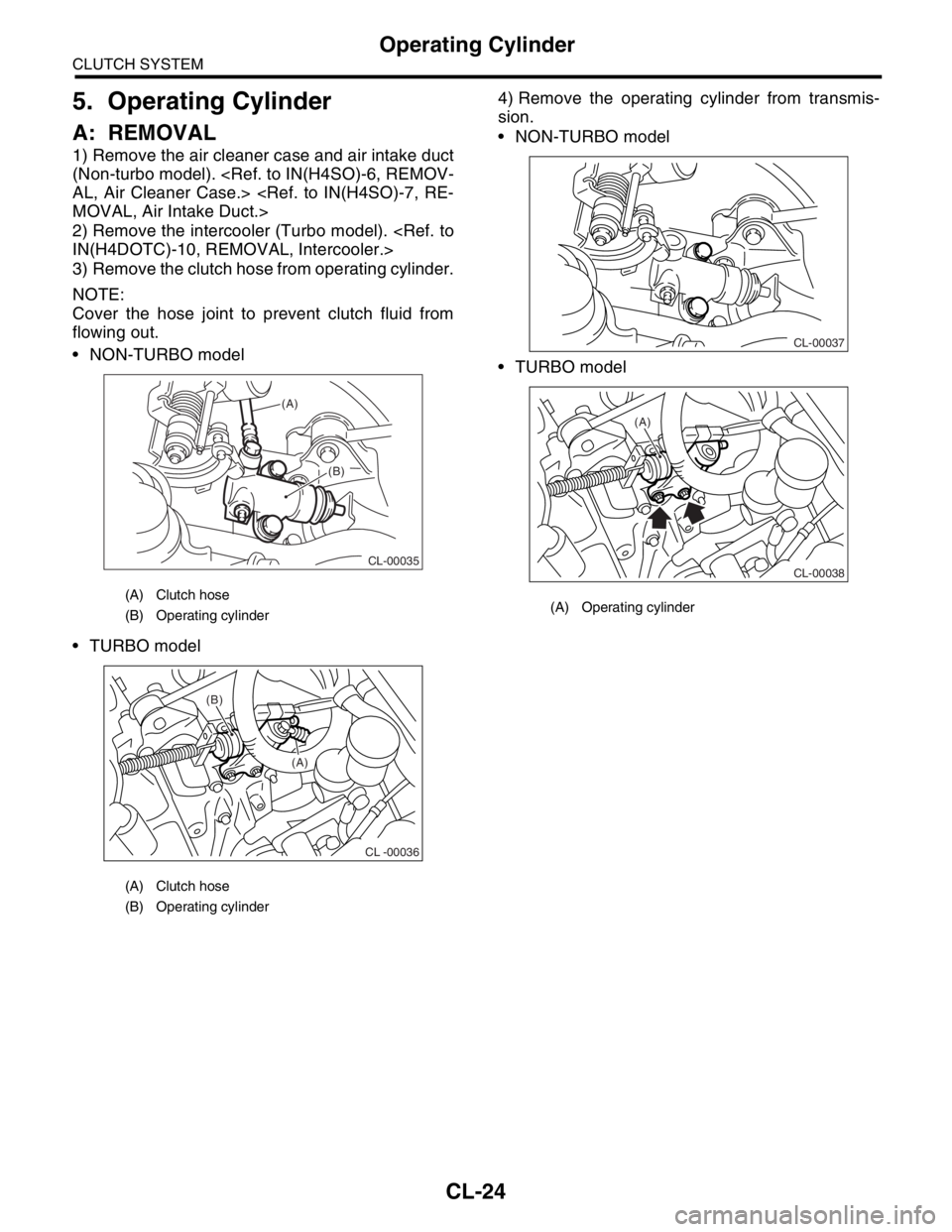
A: REMOVAL
1) Remove the air cleaner case and air intake duct
(Non-turbo model).
2) Remove the intercooler (Turbo model).
3) Remove the clutch hose from operating cylinder.
NOTE:
Cover the hose joint to prevent clutch fluid from
flowing out.
NON-TURBO model
TURBO model4) Remove the operating cylinder from transmis-
sion.
NON-TURBO model
TURBO model
(A) Clutch hose
(B) Operating cylinder
(A) Clutch hose
(B) Operating cylinder
CL-00035
(A)
(B)
CL -00036
(B)
(A)
(A) Operating cylinder
CL-00037
CL-00038
(A)