SUBARU LEGACY 1999 Service Repair Manual
Manufacturer: SUBARU, Model Year: 1999, Model line: LEGACY, Model: SUBARU LEGACY 1999Pages: 1456, PDF Size: 59.93 MB
Page 1151 of 1456
2. WAGON
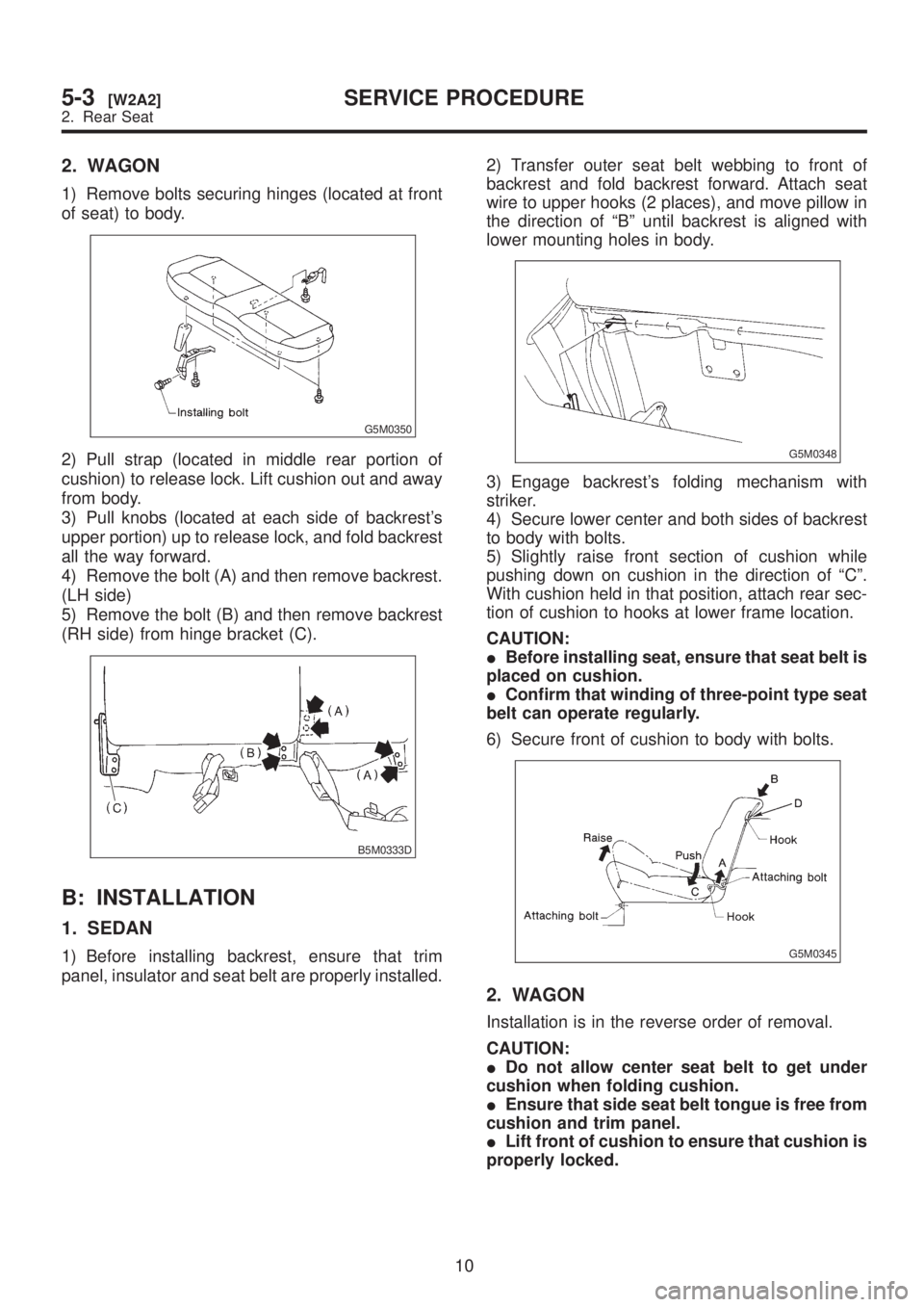
1) Remove bolts securing hinges (located at front
of seat) to body.
G5M0350
2) Pull strap (located in middle rear portion of
cushion) to release lock. Lift cushion out and away
from body.
3) Pull knobs (located at each side of backrest's
upper portion) up to release lock, and fold backrest
all the way forward.
4) Remove the bolt (A) and then remove backrest.
(LH side)
5) Remove the bolt (B) and then remove backrest
(RH side) from hinge bracket (C).
B5M0333D
B: INSTALLATION
1. SEDAN
1) Before installing backrest, ensure that trim
panel, insulator and seat belt are properly installed.2) Transfer outer seat belt webbing to front of
backrest and fold backrest forward. Attach seat
wire to upper hooks (2 places), and move pillow in
the direction of ªBº until backrest is aligned with
lower mounting holes in body.
G5M0348
3) Engage backrest's folding mechanism with
striker.
4) Secure lower center and both sides of backrest
to body with bolts.
5) Slightly raise front section of cushion while
pushing down on cushion in the direction of ªCº.
With cushion held in that position, attach rear sec-
tion of cushion to hooks at lower frame location.
CAUTION:
IBefore installing seat, ensure that seat belt is
placed on cushion.
IConfirm that winding of three-point type seat
belt can operate regularly.
6) Secure front of cushion to body with bolts.
G5M0345
2. WAGON
Installation is in the reverse order of removal.
CAUTION:
IDo not allow center seat belt to get under
cushion when folding cushion.
IEnsure that side seat belt tongue is free from
cushion and trim panel.
ILift front of cushion to ensure that cushion is
properly locked.
10
5-3[W2A2]SERVICE PROCEDURE
2. Rear Seat
Page 1152 of 1456
3. Front Seat Belt
A: REMOVAL AND INSTALLATION
1. OUTER BELT
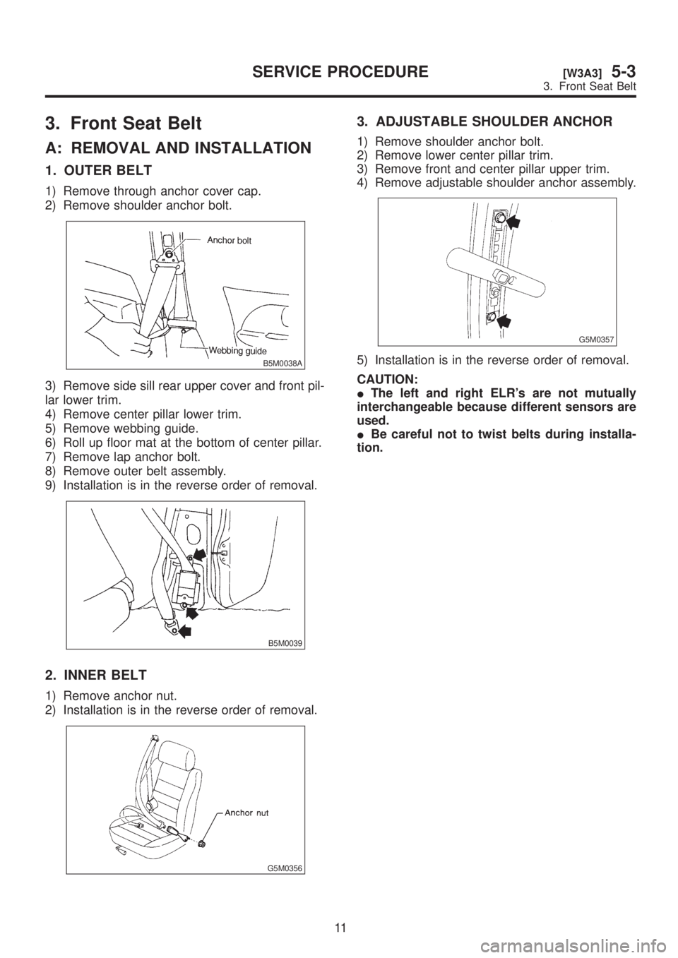
1) Remove through anchor cover cap.
2) Remove shoulder anchor bolt.
B5M0038A
3) Remove side sill rear upper cover and front pil-
lar lower trim.
4) Remove center pillar lower trim.
5) Remove webbing guide.
6) Roll up floor mat at the bottom of center pillar.
7) Remove lap anchor bolt.
8) Remove outer belt assembly.
9) Installation is in the reverse order of removal.
B5M0039
2. INNER BELT
1) Remove anchor nut.
2) Installation is in the reverse order of removal.
G5M0356
3. ADJUSTABLE SHOULDER ANCHOR
1) Remove shoulder anchor bolt.
2) Remove lower center pillar trim.
3) Remove front and center pillar upper trim.
4) Remove adjustable shoulder anchor assembly.
G5M0357
5) Installation is in the reverse order of removal.
CAUTION:
IThe left and right ELR's are not mutually
interchangeable because different sensors are
used.
IBe careful not to twist belts during installa-
tion.
11
[W3A3]5-3SERVICE PROCEDURE
3. Front Seat Belt
Page 1153 of 1456
4. Rear Seat Belt
A: REMOVAL AND INSTALLATION
1. SEDAN
1) Remove rear cushion from vehicle.
2) Remove rear backrest from vehicle.
3) Remove rear pillar upper trim.
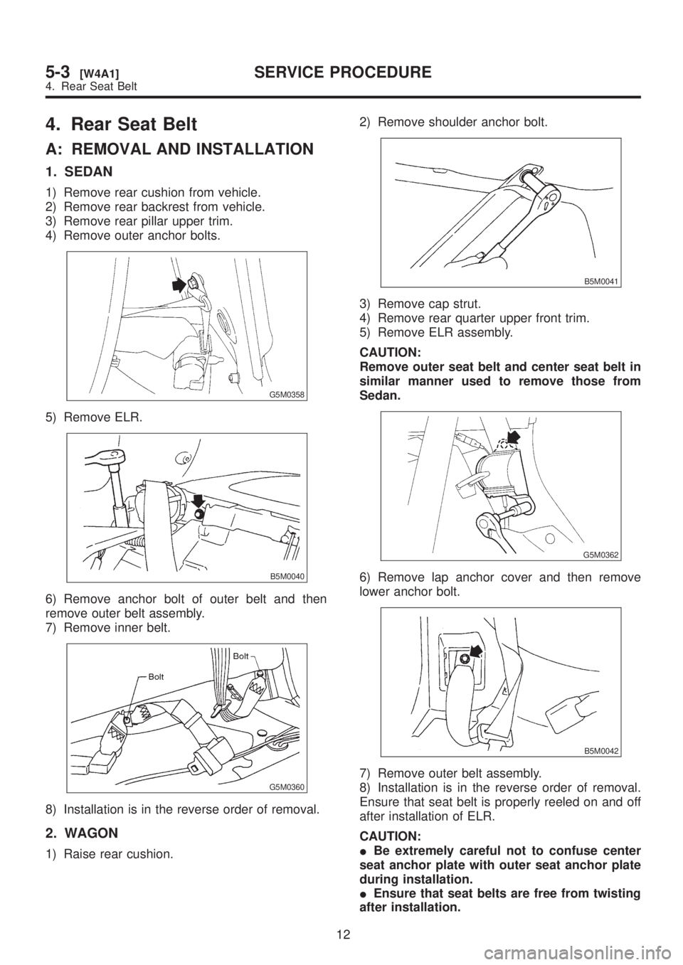
4) Remove outer anchor bolts.
G5M0358
5) Remove ELR.
B5M0040
6) Remove anchor bolt of outer belt and then
remove outer belt assembly.
7) Remove inner belt.
G5M0360
8) Installation is in the reverse order of removal.
2. WAGON
1) Raise rear cushion.2) Remove shoulder anchor bolt.
B5M0041
3) Remove cap strut.
4) Remove rear quarter upper front trim.
5) Remove ELR assembly.
CAUTION:
Remove outer seat belt and center seat belt in
similar manner used to remove those from
Sedan.
G5M0362
6) Remove lap anchor cover and then remove
lower anchor bolt.
B5M0042
7) Remove outer belt assembly.
8) Installation is in the reverse order of removal.
Ensure that seat belt is properly reeled on and off
after installation of ELR.
CAUTION:
IBe extremely careful not to confuse center
seat anchor plate with outer seat anchor plate
during installation.
IEnsure that seat belts are free from twisting
after installation.
12
5-3[W4A1]SERVICE PROCEDURE
4. Rear Seat Belt
Page 1154 of 1456
IEnsure that tongues, buckles and belts are
properly placed on seat.5. Inner Trim Panel
A: REMOVAL AND INSTALLATION
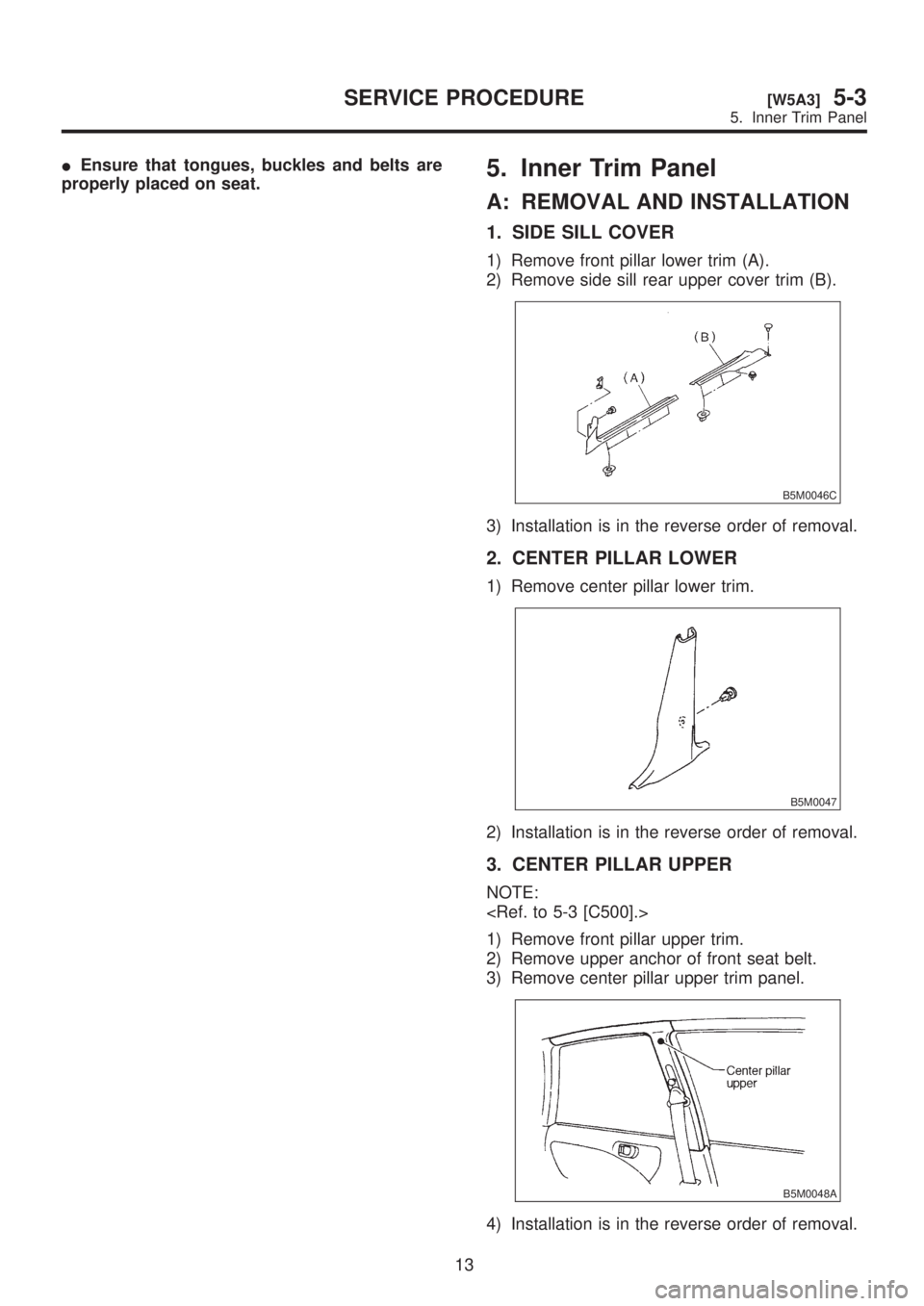
1. SIDE SILL COVER
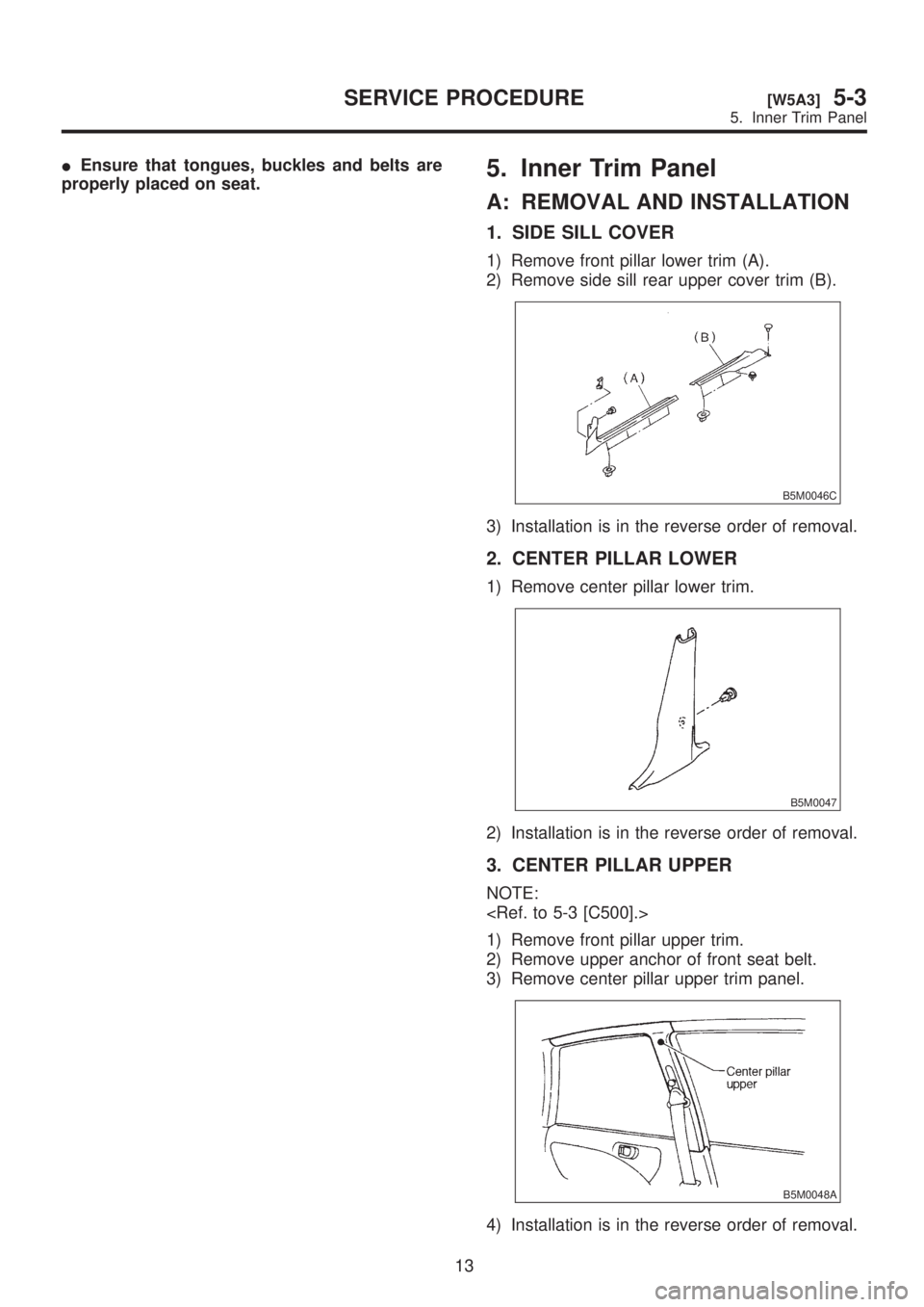
1) Remove front pillar lower trim (A).
2) Remove side sill rear upper cover trim (B).
B5M0046C
3) Installation is in the reverse order of removal.
2. CENTER PILLAR LOWER
1) Remove center pillar lower trim.
B5M0047
2) Installation is in the reverse order of removal.
3. CENTER PILLAR UPPER
NOTE:
1) Remove front pillar upper trim.
2) Remove upper anchor of front seat belt.
3) Remove center pillar upper trim panel.
B5M0048A
4) Installation is in the reverse order of removal.
13
[W5A3]5-3SERVICE PROCEDURE
5. Inner Trim Panel
Page 1155 of 1456
IEnsure that tongues, buckles and belts are
properly placed on seat.5. Inner Trim Panel
A: REMOVAL AND INSTALLATION
1. SIDE SILL COVER
1) Remove front pillar lower trim (A).
2) Remove side sill rear upper cover trim (B).
B5M0046C
3) Installation is in the reverse order of removal.
2. CENTER PILLAR LOWER
1) Remove center pillar lower trim.
B5M0047
2) Installation is in the reverse order of removal.
3. CENTER PILLAR UPPER
NOTE:
1) Remove front pillar upper trim.
2) Remove upper anchor of front seat belt.
3) Remove center pillar upper trim panel.
B5M0048A
4) Installation is in the reverse order of removal.
13
[W5A3]5-3SERVICE PROCEDURE
5. Inner Trim Panel
Page 1156 of 1456
CAUTION:
IThe left and right ELR's are not mutually
interchangeable because different sensors are
used.
IBe careful not to twist belts during installa-
tion.
4. FRONT PILLAR UPPER
NOTE:
1) Remove front pillar upper trim panel.
CAUTION:
Be sure to securely hook pawls of front pillar
upper trim panel on body flange.
G5M0363
2) Installation is in the reverse order of removal.
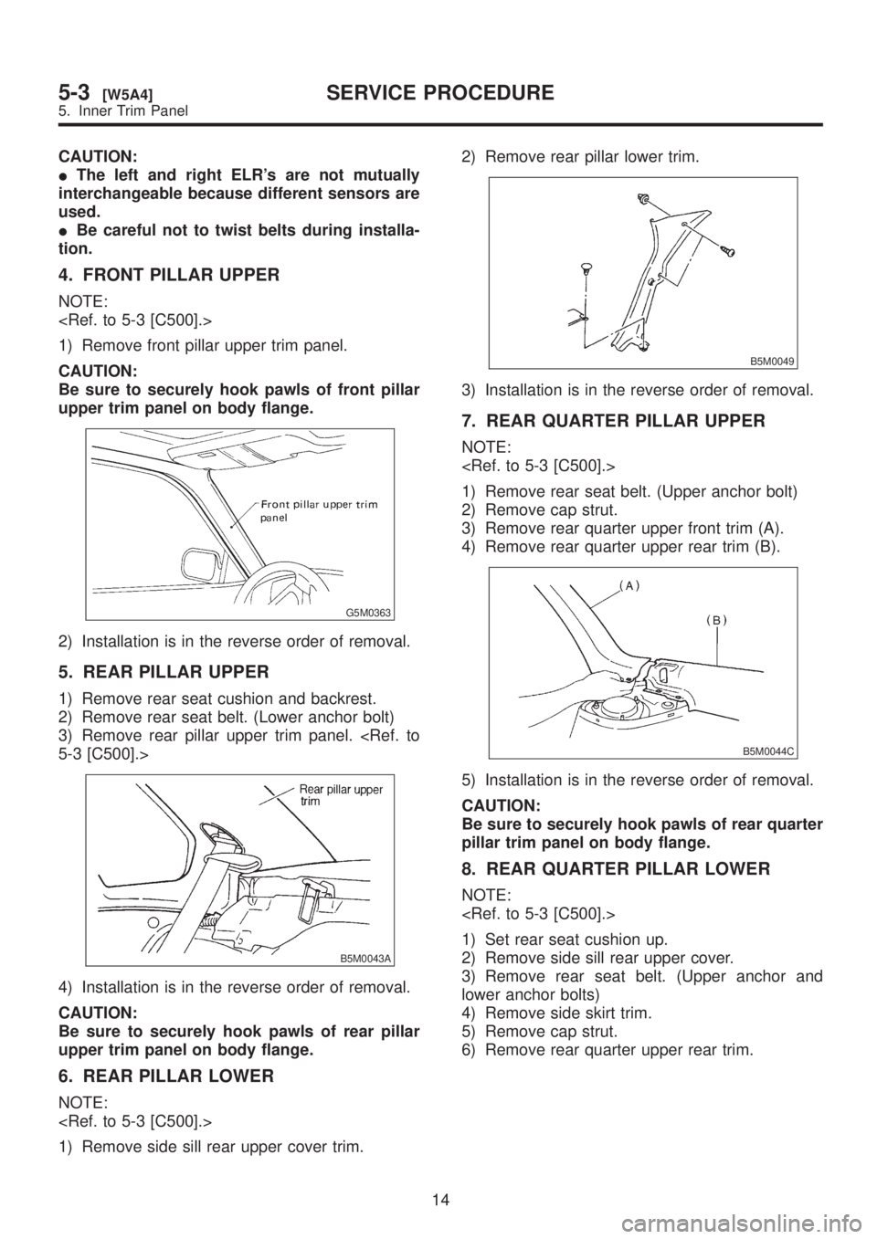
5. REAR PILLAR UPPER
1) Remove rear seat cushion and backrest.
2) Remove rear seat belt. (Lower anchor bolt)
3) Remove rear pillar upper trim panel.
B5M0043A
4) Installation is in the reverse order of removal.
CAUTION:
Be sure to securely hook pawls of rear pillar
upper trim panel on body flange.
6. REAR PILLAR LOWER
NOTE:
1) Remove side sill rear upper cover trim.2) Remove rear pillar lower trim.
B5M0049
3) Installation is in the reverse order of removal.
7. REAR QUARTER PILLAR UPPER
NOTE:
1) Remove rear seat belt. (Upper anchor bolt)
2) Remove cap strut.
3) Remove rear quarter upper front trim (A).
4) Remove rear quarter upper rear trim (B).
B5M0044C
5) Installation is in the reverse order of removal.
CAUTION:
Be sure to securely hook pawls of rear quarter
pillar trim panel on body flange.
8. REAR QUARTER PILLAR LOWER
NOTE:
1) Set rear seat cushion up.
2) Remove side sill rear upper cover.
3) Remove rear seat belt. (Upper anchor and
lower anchor bolts)
4) Remove side skirt trim.
5) Remove cap strut.
6) Remove rear quarter upper rear trim.
14
5-3[W5A4]SERVICE PROCEDURE
5. Inner Trim Panel
Page 1157 of 1456
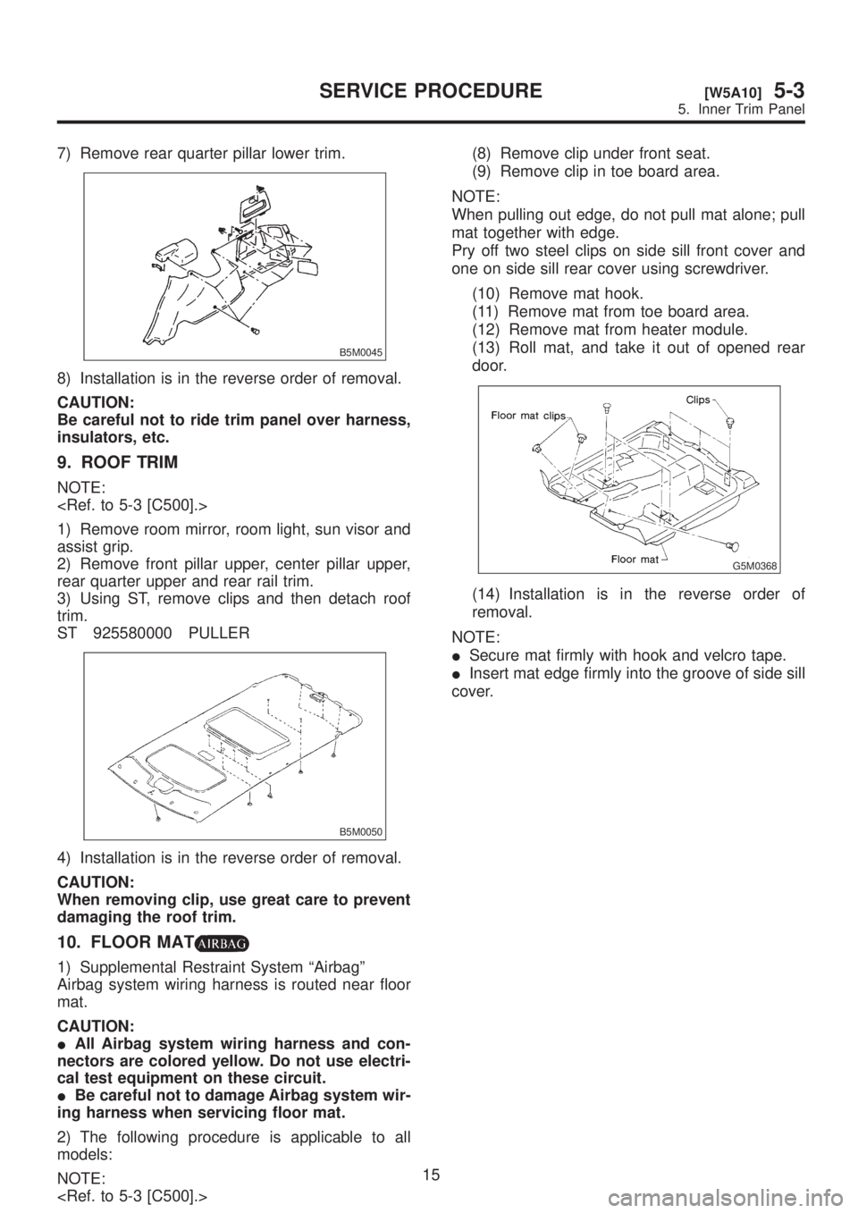
7) Remove rear quarter pillar lower trim.
B5M0045
8) Installation is in the reverse order of removal.
CAUTION:
Be careful not to ride trim panel over harness,
insulators, etc.
9. ROOF TRIM
NOTE:
1) Remove room mirror, room light, sun visor and
assist grip.
2) Remove front pillar upper, center pillar upper,
rear quarter upper and rear rail trim.
3) Using ST, remove clips and then detach roof
trim.
ST 925580000 PULLER
B5M0050
4) Installation is in the reverse order of removal.
CAUTION:
When removing clip, use great care to prevent
damaging the roof trim.
10. FLOOR MAT
1) Supplemental Restraint System ªAirbagº
Airbag system wiring harness is routed near floor
mat.
CAUTION:
IAll Airbag system wiring harness and con-
nectors are colored yellow. Do not use electri-
cal test equipment on these circuit.
IBe careful not to damage Airbag system wir-
ing harness when servicing floor mat.
2) The following procedure is applicable to all
models:
NOTE:
(9) Remove clip in toe board area.
NOTE:
When pulling out edge, do not pull mat alone; pull
mat together with edge.
Pry off two steel clips on side sill front cover and
one on side sill rear cover using screwdriver.
(10) Remove mat hook.
(11) Remove mat from toe board area.
(12) Remove mat from heater module.
(13) Roll mat, and take it out of opened rear
door.
G5M0368
(14) Installation is in the reverse order of
removal.
NOTE:
ISecure mat firmly with hook and velcro tape.
IInsert mat edge firmly into the groove of side sill
cover.
15
[W5A10]5-3SERVICE PROCEDURE
5. Inner Trim Panel
Page 1158 of 1456
MEMO:
16
5-3SERVICE PROCEDURE
Page 1159 of 1456
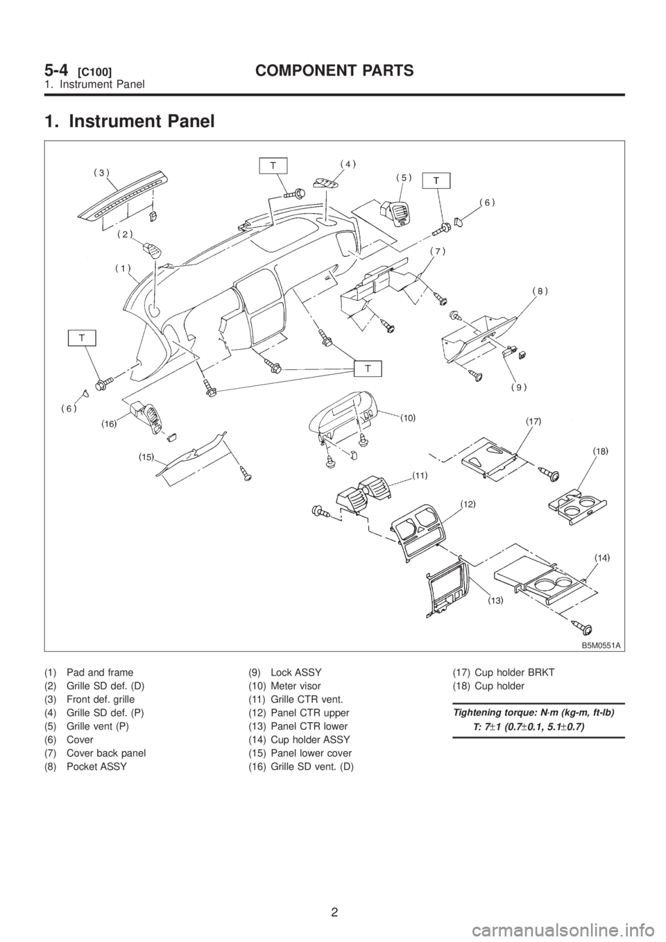
1. Instrument Panel
B5M0551A
(1) Pad and frame
(2) Grille SD def. (D)
(3) Front def. grille
(4) Grille SD def. (P)
(5) Grille vent (P)
(6) Cover
(7) Cover back panel
(8) Pocket ASSY(9) Lock ASSY
(10) Meter visor
(11) Grille CTR vent.
(12) Panel CTR upper
(13) Panel CTR lower
(14) Cup holder ASSY
(15) Panel lower cover
(16) Grille SD vent. (D)(17) Cup holder BRKT
(18) Cup holder
Tightening torque: N´m (kg-m, ft-lb)
T:
7±1 (0.7±0.1, 5.1±0.7)
2
5-4[C100]COMPONENT PARTS
1. Instrument Panel
Page 1160 of 1456
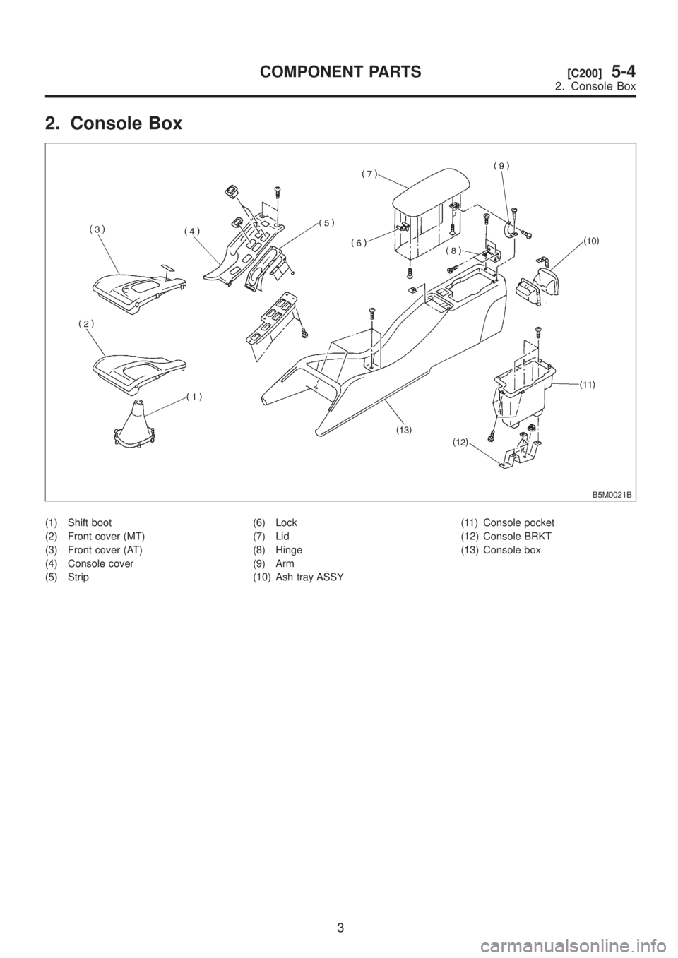
2. Console Box
B5M0021B
(1) Shift boot
(2) Front cover (MT)
(3) Front cover (AT)
(4) Console cover
(5) Strip(6) Lock
(7) Lid
(8) Hinge
(9) Arm
(10) Ash tray ASSY(11) Console pocket
(12) Console BRKT
(13) Console box
3
[C200]5-4COMPONENT PARTS
2. Console Box