SUBARU LEGACY 1999 Service Repair Manual
Manufacturer: SUBARU, Model Year: 1999, Model line: LEGACY, Model: SUBARU LEGACY 1999Pages: 1456, PDF Size: 59.93 MB
Page 1191 of 1456
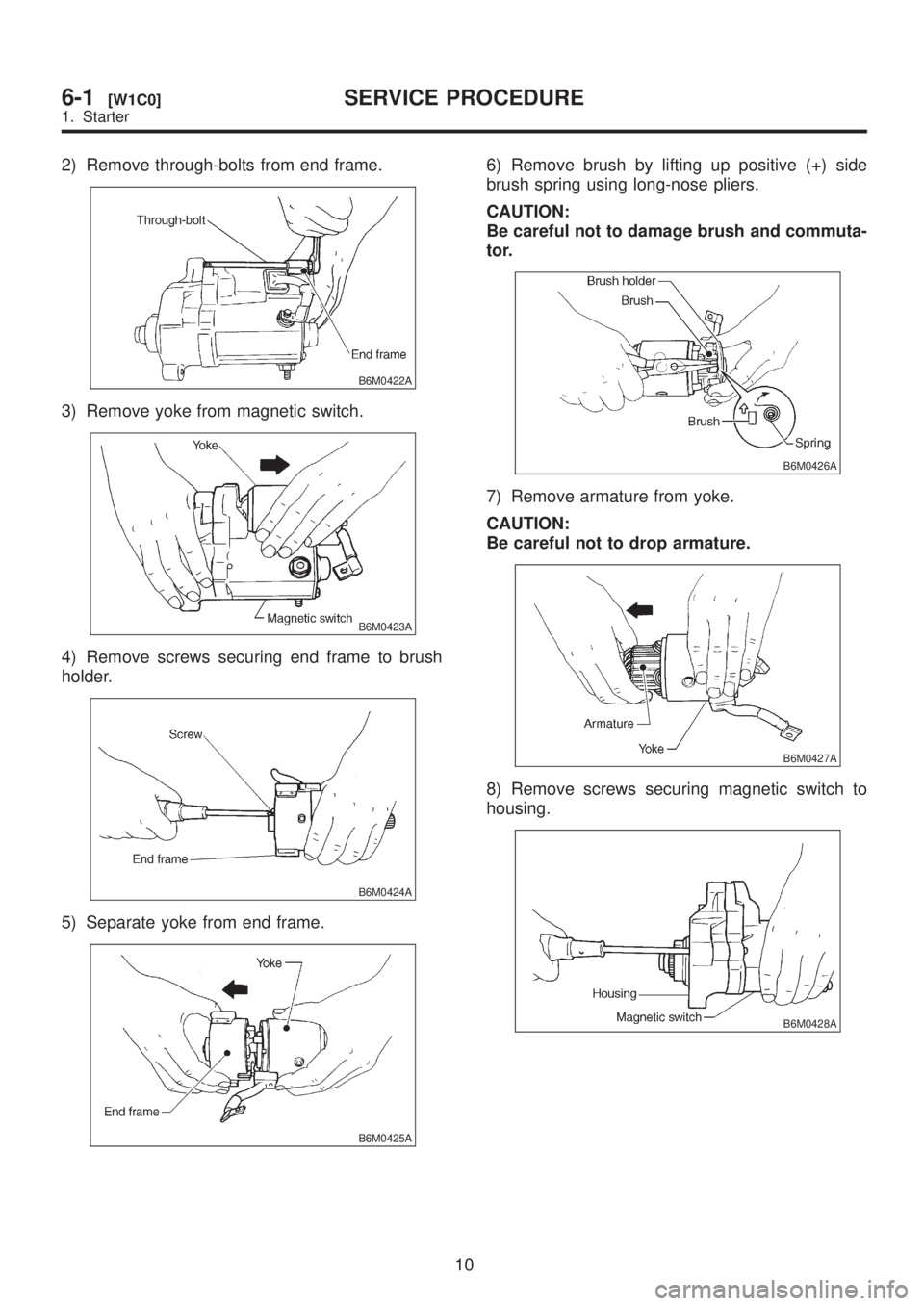
2) Remove through-bolts from end frame.
B6M0422A
3) Remove yoke from magnetic switch.
B6M0423A
4) Remove screws securing end frame to brush
holder.
B6M0424A
5) Separate yoke from end frame.
B6M0425A
6) Remove brush by lifting up positive (+) side
brush spring using long-nose pliers.
CAUTION:
Be careful not to damage brush and commuta-
tor.
B6M0426A
7) Remove armature from yoke.
CAUTION:
Be careful not to drop armature.
B6M0427A
8) Remove screws securing magnetic switch to
housing.
B6M0428A
10
6-1[W1C0]SERVICE PROCEDURE
1. Starter
Page 1192 of 1456
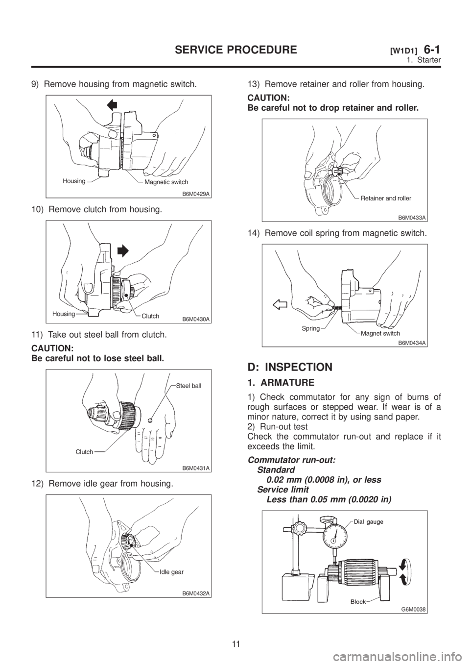
9) Remove housing from magnetic switch.
B6M0429A
10) Remove clutch from housing.
B6M0430A
11) Take out steel ball from clutch.
CAUTION:
Be careful not to lose steel ball.
B6M0431A
12) Remove idle gear from housing.
B6M0432A
13) Remove retainer and roller from housing.
CAUTION:
Be careful not to drop retainer and roller.
B6M0433A
14) Remove coil spring from magnetic switch.
B6M0434A
D: INSPECTION
1. ARMATURE
1) Check commutator for any sign of burns of
rough surfaces or stepped wear. If wear is of a
minor nature, correct it by using sand paper.
2) Run-out test
Check the commutator run-out and replace if it
exceeds the limit.
Commutator run-out:
Standard
0.02 mm (0.0008 in), or less
Service limit
Less than 0.05 mm (0.0020 in)
G6M0038
11
[W1D1]6-1SERVICE PROCEDURE
1. Starter
Page 1193 of 1456
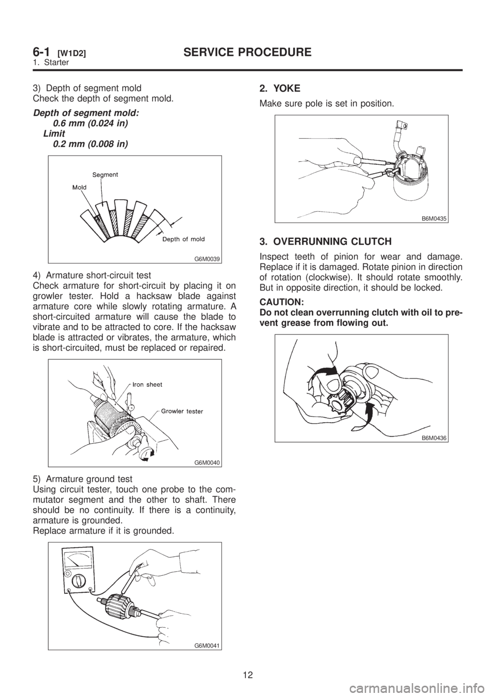
3) Depth of segment mold
Check the depth of segment mold.
Depth of segment mold:
0.6 mm (0.024 in)
Limit
0.2 mm (0.008 in)
G6M0039
4) Armature short-circuit test
Check armature for short-circuit by placing it on
growler tester. Hold a hacksaw blade against
armature core while slowly rotating armature. A
short-circuited armature will cause the blade to
vibrate and to be attracted to core. If the hacksaw
blade is attracted or vibrates, the armature, which
is short-circuited, must be replaced or repaired.
G6M0040
5) Armature ground test
Using circuit tester, touch one probe to the com-
mutator segment and the other to shaft. There
should be no continuity. If there is a continuity,
armature is grounded.
Replace armature if it is grounded.
G6M0041
2. YOKE
Make sure pole is set in position.
B6M0435
3. OVERRUNNING CLUTCH
Inspect teeth of pinion for wear and damage.
Replace if it is damaged. Rotate pinion in direction
of rotation (clockwise). It should rotate smoothly.
But in opposite direction, it should be locked.
CAUTION:
Do not clean overrunning clutch with oil to pre-
vent grease from flowing out.
B6M0436
12
6-1[W1D2]SERVICE PROCEDURE
1. Starter
Page 1194 of 1456
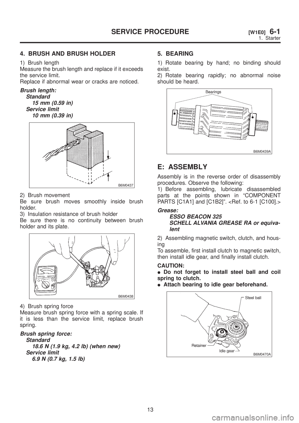
4. BRUSH AND BRUSH HOLDER
1) Brush length
Measure the brush length and replace if it exceeds
the service limit.
Replace if abnormal wear or cracks are noticed.
Brush length:
Standard
15 mm (0.59 in)
Service limit
10 mm (0.39 in)
B6M0437
2) Brush movement
Be sure brush moves smoothly inside brush
holder.
3) Insulation resistance of brush holder
Be sure there is no continuity between brush
holder and its plate.
B6M0438
4) Brush spring force
Measure brush spring force with a spring scale. If
it is less than the service limit, replace brush
spring.
Brush spring force:
Standard
18.6 N (1.9 kg, 4.2 lb) (when new)
Service limit
6.9 N (0.7 kg, 1.5 lb)
5. BEARING
1) Rotate bearing by hand; no binding should
exist.
2) Rotate bearing rapidly; no abnormal noise
should be heard.
B6M0439A
E: ASSEMBLY
Assembly is in the reverse order of disassembly
procedures. Observe the following:
1) Before assembling, lubricate disassembled
parts at the points shown in ªCOMPONENT
PARTS [C1A1] and [C1B2]º.
Grease:
ESSO BEACON 325
SCHELL ALVANIA GREASE RA or equiva-
lent
2) Assembling magnetic switch, clutch, and hous-
ing
To assemble, first install clutch to magnetic switch,
then install idle gear, and finally install clutch.
CAUTION:
IDo not forget to install steel ball and coil
spring to clutch.
IAttach bearing to idle gear beforehand.
B6M0470A
13
[W1E0]6-1SERVICE PROCEDURE
1. Starter
Page 1195 of 1456
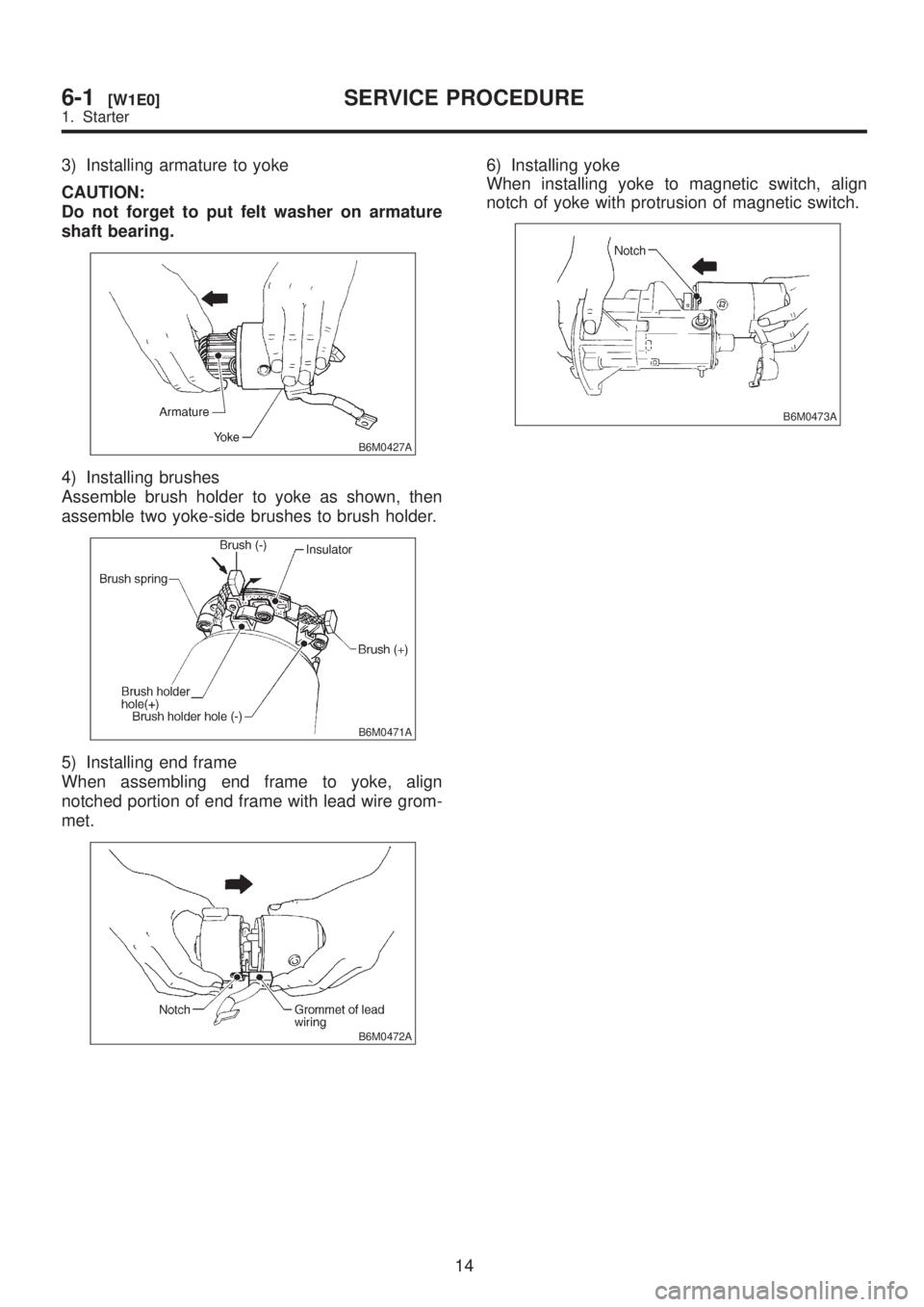
3) Installing armature to yoke
CAUTION:
Do not forget to put felt washer on armature
shaft bearing.
B6M0427A
4) Installing brushes
Assemble brush holder to yoke as shown, then
assemble two yoke-side brushes to brush holder.
B6M0471A
5) Installing end frame
When assembling end frame to yoke, align
notched portion of end frame with lead wire grom-
met.
B6M0472A
6) Installing yoke
When installing yoke to magnetic switch, align
notch of yoke with protrusion of magnetic switch.
B6M0473A
14
6-1[W1E0]SERVICE PROCEDURE
1. Starter
Page 1196 of 1456
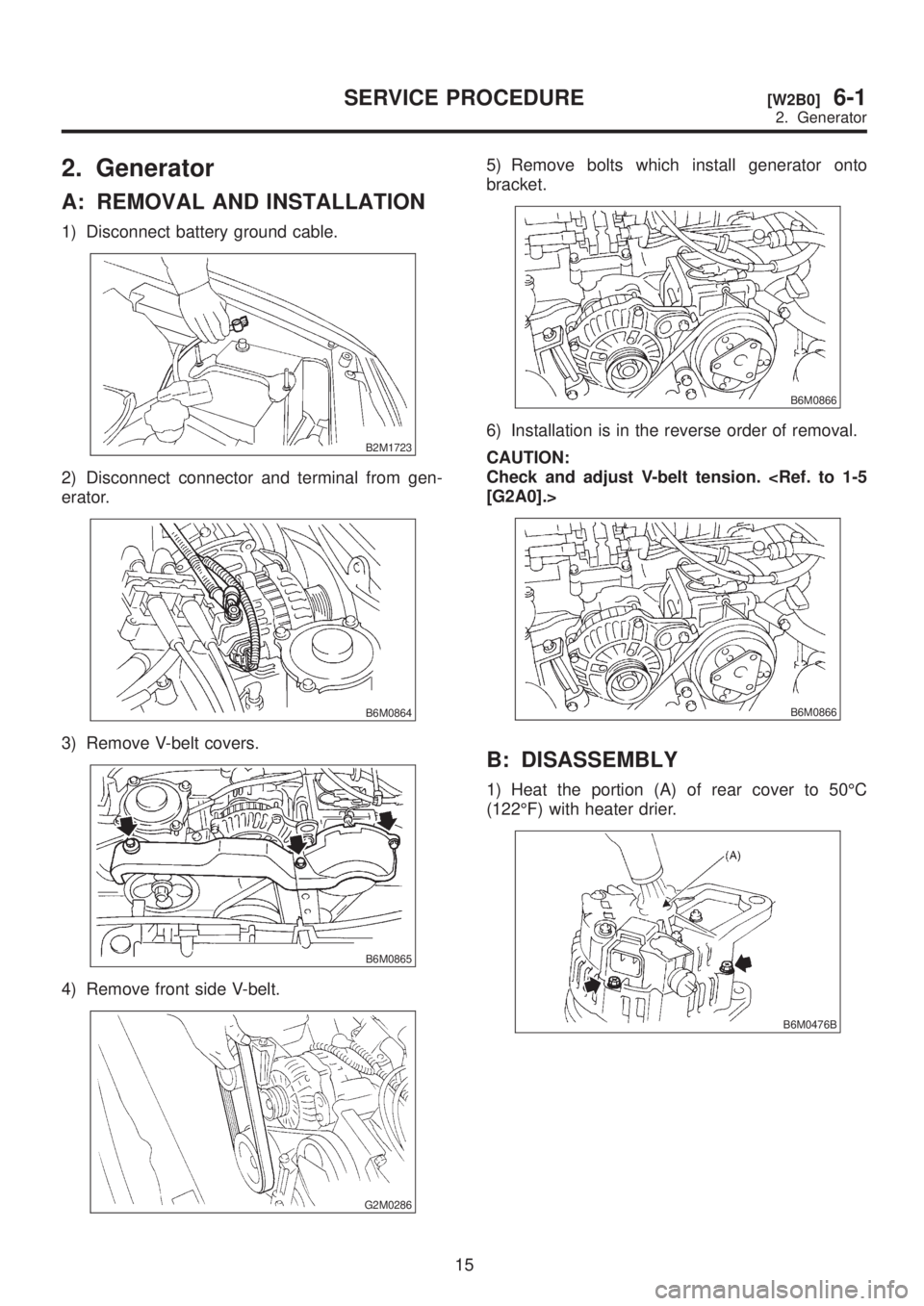
2. Generator
A: REMOVAL AND INSTALLATION
1) Disconnect battery ground cable.
B2M1723
2) Disconnect connector and terminal from gen-
erator.
B6M0864
3) Remove V-belt covers.
B6M0865
4) Remove front side V-belt.
G2M0286
5) Remove bolts which install generator onto
bracket.
B6M0866
6) Installation is in the reverse order of removal.
CAUTION:
Check and adjust V-belt tension.
B6M0866
B: DISASSEMBLY
1) Heat the portion (A) of rear cover to 50ÉC
(122ÉF) with heater drier.
B6M0476B
15
[W2B0]6-1SERVICE PROCEDURE
2. Generator
Page 1197 of 1456
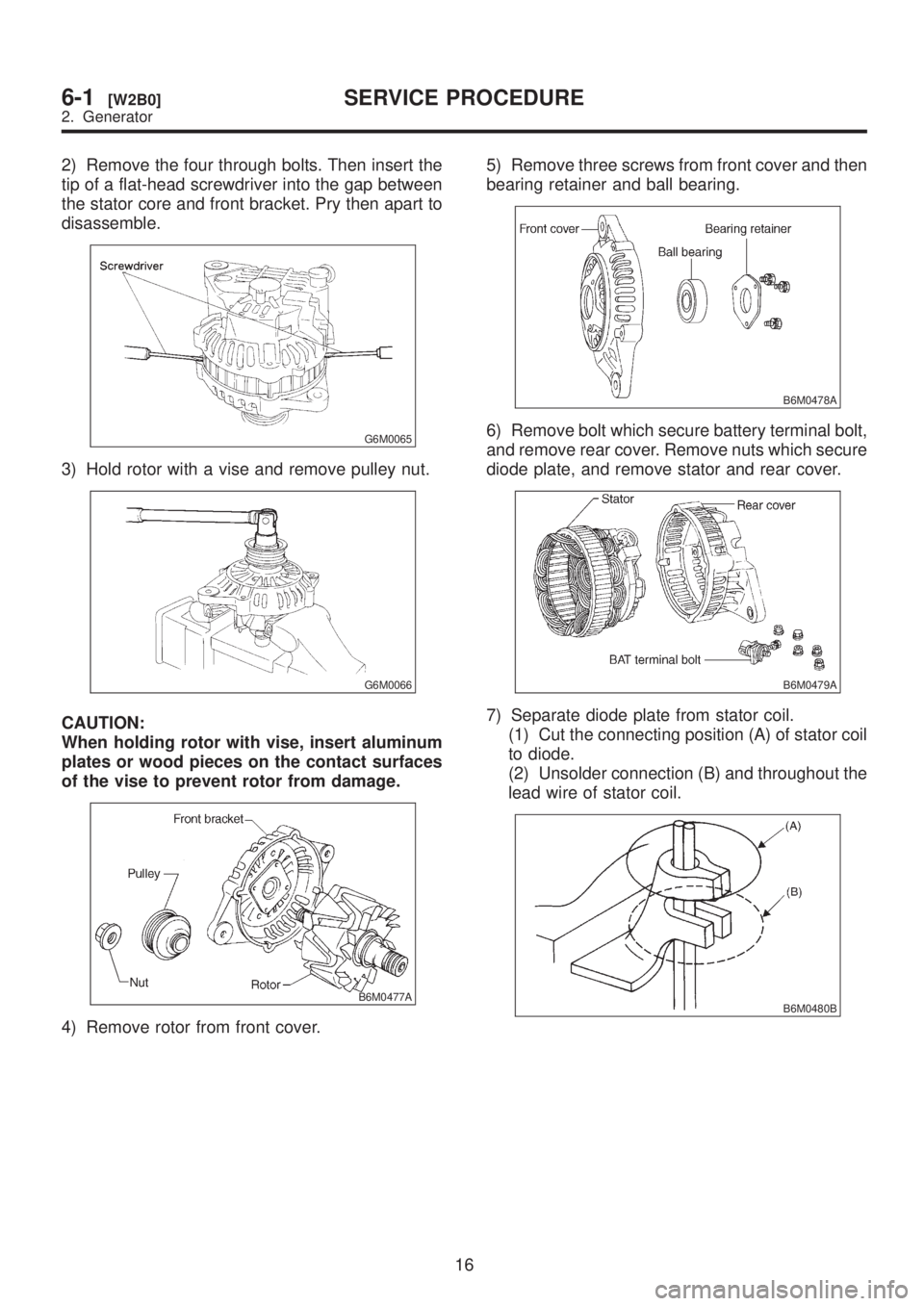
2) Remove the four through bolts. Then insert the
tip of a flat-head screwdriver into the gap between
the stator core and front bracket. Pry then apart to
disassemble.
G6M0065
3) Hold rotor with a vise and remove pulley nut.
G6M0066
CAUTION:
When holding rotor with vise, insert aluminum
plates or wood pieces on the contact surfaces
of the vise to prevent rotor from damage.
B6M0477A
4) Remove rotor from front cover.5) Remove three screws from front cover and then
bearing retainer and ball bearing.
B6M0478A
6) Remove bolt which secure battery terminal bolt,
and remove rear cover. Remove nuts which secure
diode plate, and remove stator and rear cover.
B6M0479A
7) Separate diode plate from stator coil.
(1) Cut the connecting position (A) of stator coil
to diode.
(2) Unsolder connection (B) and throughout the
lead wire of stator coil.
B6M0480B
16
6-1[W2B0]SERVICE PROCEDURE
2. Generator
Page 1198 of 1456
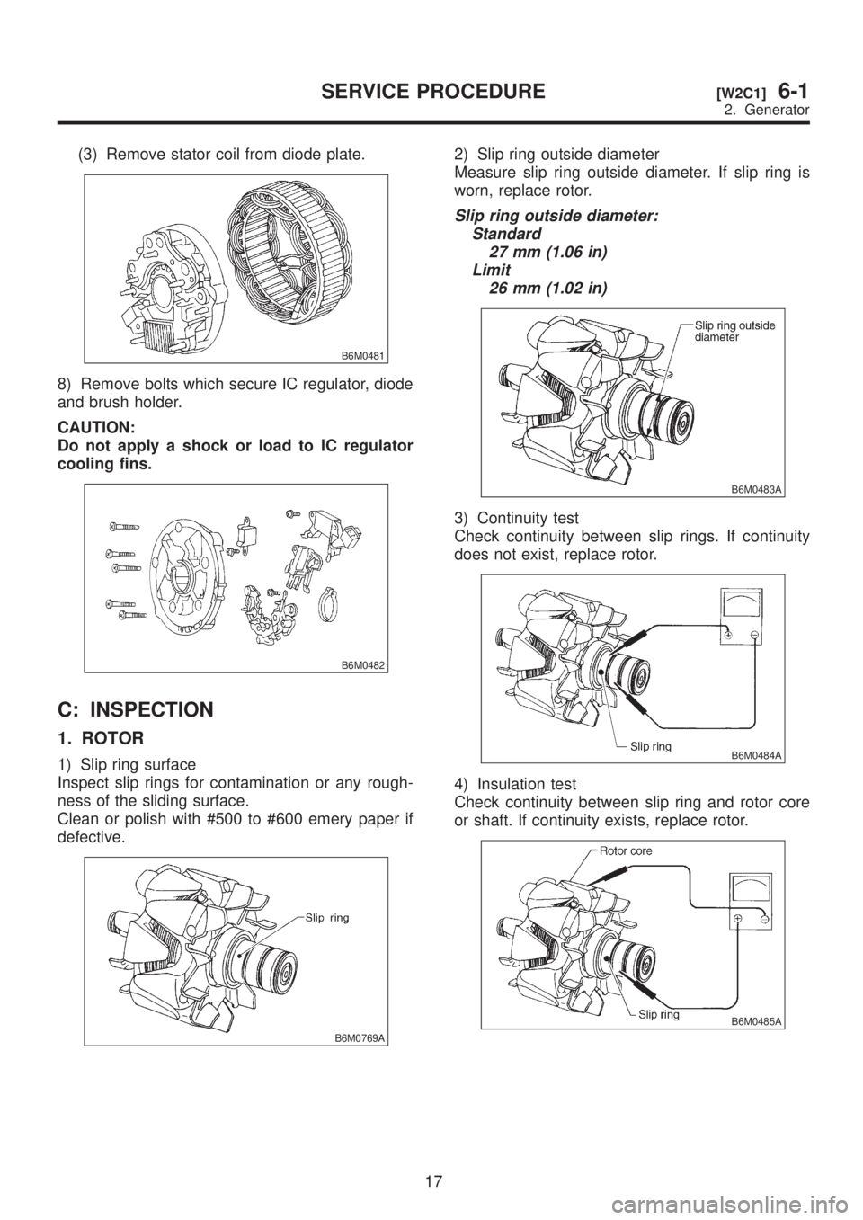
(3) Remove stator coil from diode plate.
B6M0481
8) Remove bolts which secure IC regulator, diode
and brush holder.
CAUTION:
Do not apply a shock or load to IC regulator
cooling fins.
B6M0482
C: INSPECTION
1. ROTOR
1) Slip ring surface
Inspect slip rings for contamination or any rough-
ness of the sliding surface.
Clean or polish with #500 to #600 emery paper if
defective.
B6M0769A
2) Slip ring outside diameter
Measure slip ring outside diameter. If slip ring is
worn, replace rotor.
Slip ring outside diameter:
Standard
27 mm (1.06 in)
Limit
26 mm (1.02 in)
B6M0483A
3) Continuity test
Check continuity between slip rings. If continuity
does not exist, replace rotor.
B6M0484A
4) Insulation test
Check continuity between slip ring and rotor core
or shaft. If continuity exists, replace rotor.
B6M0485A
17
[W2C1]6-1SERVICE PROCEDURE
2. Generator
Page 1199 of 1456
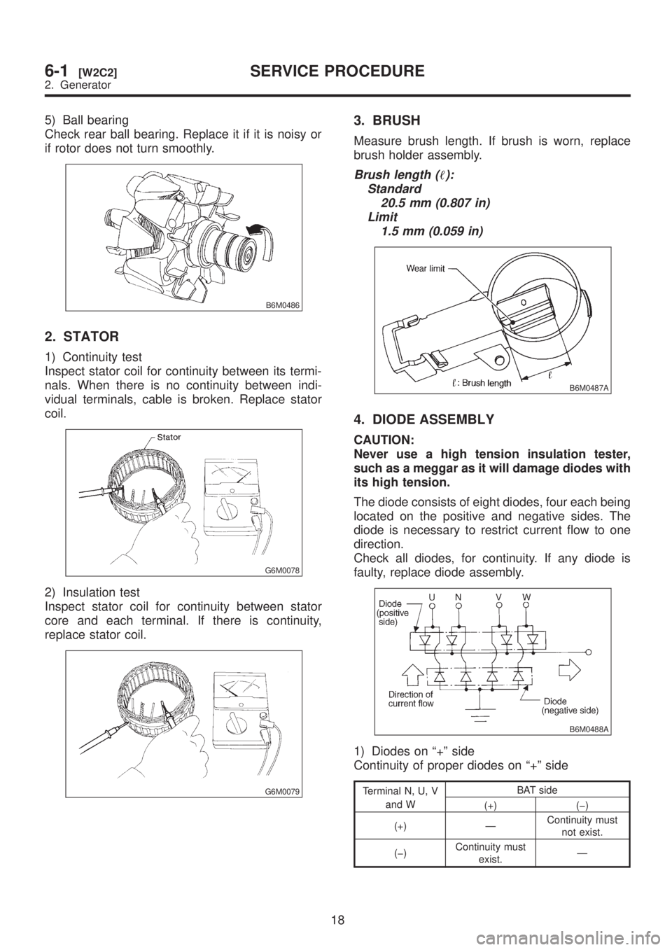
5) Ball bearing
Check rear ball bearing. Replace it if it is noisy or
if rotor does not turn smoothly.
B6M0486
2. STATOR
1) Continuity test
Inspect stator coil for continuity between its termi-
nals. When there is no continuity between indi-
vidual terminals, cable is broken. Replace stator
coil.
G6M0078
2) Insulation test
Inspect stator coil for continuity between stator
core and each terminal. If there is continuity,
replace stator coil.
G6M0079
3. BRUSH
Measure brush length. If brush is worn, replace
brush holder assembly.
Brush length ():
Standard
20.5 mm (0.807 in)
Limit
1.5 mm (0.059 in)
B6M0487A
4. DIODE ASSEMBLY
CAUTION:
Never use a high tension insulation tester,
such as a meggar as it will damage diodes with
its high tension.
The diode consists of eight diodes, four each being
located on the positive and negative sides. The
diode is necessary to restrict current flow to one
direction.
Check all diodes, for continuity. If any diode is
faulty, replace diode assembly.
B6M0488A
1) Diodes on ª+º side
Continuity of proper diodes on ª+º side
Terminal N, U, V
and WBAT side
(+) (þ)
(+) ÐContinuity must
not exist.
(þ)Continuity must
exist.Ð
18
6-1[W2C2]SERVICE PROCEDURE
2. Generator
Page 1200 of 1456
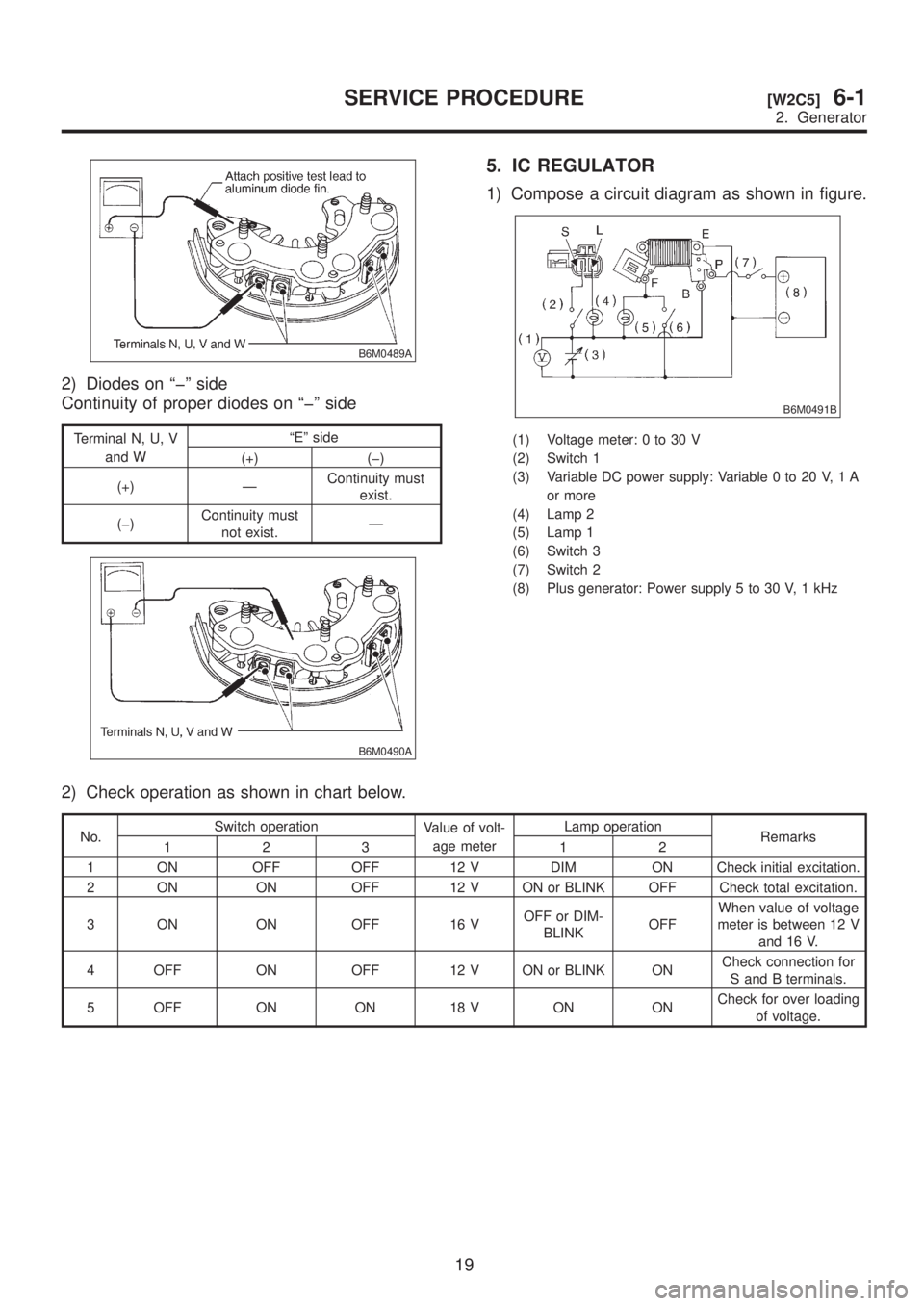
B6M0489A
2) Diodes on ªþº side
Continuity of proper diodes on ªþº side
Terminal N, U, V
and WªEº side
(+) (þ)
(+) ÐContinuity must
exist.
(þ)Continuity must
not exist.Ð
B6M0490A
5. IC REGULATOR
1) Compose a circuit diagram as shown in figure.
B6M0491B
(1) Voltage meter: 0 to 30 V
(2) Switch 1
(3) Variable DC power supply: Variable 0 to 20 V, 1 A
or more
(4) Lamp 2
(5) Lamp 1
(6) Switch 3
(7) Switch 2
(8) Plus generator: Power supply 5 to 30 V, 1 kHz
2) Check operation as shown in chart below.
No.Switch operation
Value of volt-
age meterLamp operation
Remarks
123 12
1 ON OFF OFF 12 V DIM ON Check initial excitation.
2 ON ON OFF 12 V ON or BLINK OFF Check total excitation.
3 ON ON OFF 16 VOFF or DIM-
BLINKOFFWhen value of voltage
meter is between 12 V
and 16 V.
4 OFF ON OFF 12 V ON or BLINK ONCheck connection for
S and B terminals.
5 OFF ON ON 18 V ON ONCheck for over loading
of voltage.
19
[W2C5]6-1SERVICE PROCEDURE
2. Generator