SUBARU LEGACY 1999 Service Repair Manual
Manufacturer: SUBARU, Model Year: 1999, Model line: LEGACY, Model: SUBARU LEGACY 1999Pages: 1456, PDF Size: 59.93 MB
Page 1181 of 1456
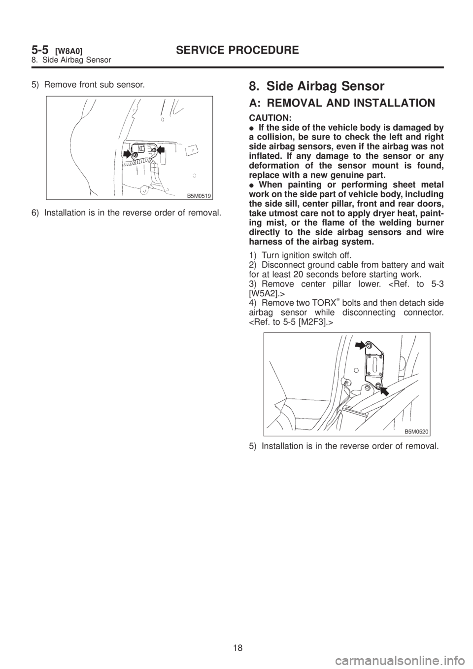
5) Remove front sub sensor.
B5M0519
6) Installation is in the reverse order of removal.
8. Side Airbag Sensor
A: REMOVAL AND INSTALLATION
CAUTION:
IIf the side of the vehicle body is damaged by
a collision, be sure to check the left and right
side airbag sensors, even if the airbag was not
inflated. If any damage to the sensor or any
deformation of the sensor mount is found,
replace with a new genuine part.
IWhen painting or performing sheet metal
work on the side part of vehicle body, including
the side sill, center pillar, front and rear doors,
take utmost care not to apply dryer heat, paint-
ing mist, or the flame of the welding burner
directly to the side airbag sensors and wire
harness of the airbag system.
1) Turn ignition switch off.
2) Disconnect ground cable from battery and wait
for at least 20 seconds before starting work.
3) Remove center pillar lower.
4) Remove two TORX
Tbolts and then detach side
airbag sensor while disconnecting connector.
B5M0520
5) Installation is in the reverse order of removal.
18
5-5[W8A0]SERVICE PROCEDURE
8. Side Airbag Sensor
Page 1182 of 1456
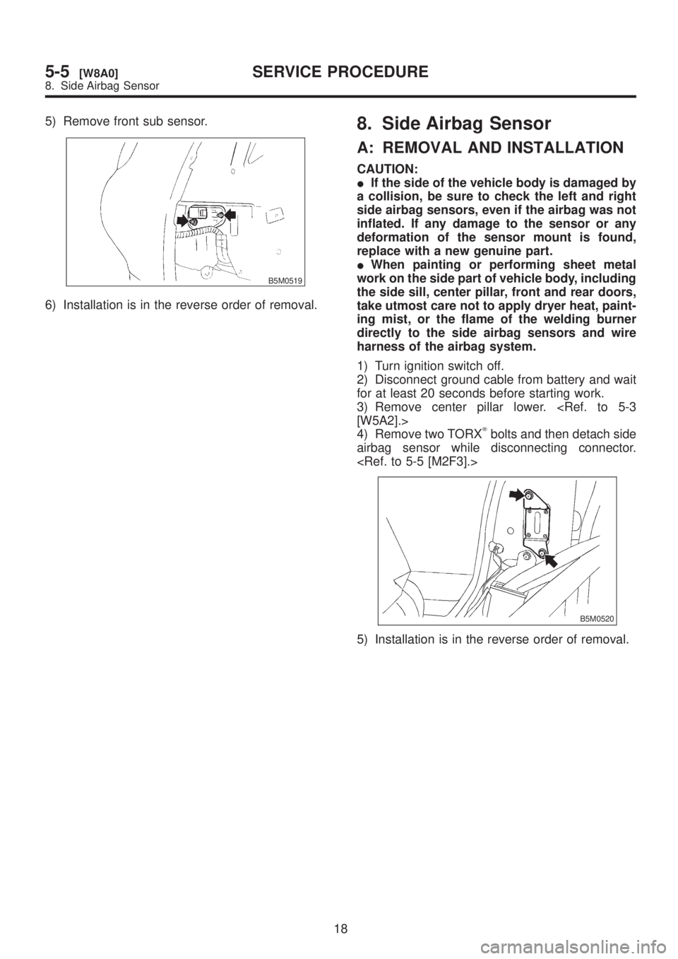
5) Remove front sub sensor.
B5M0519
6) Installation is in the reverse order of removal.
8. Side Airbag Sensor
A: REMOVAL AND INSTALLATION
CAUTION:
IIf the side of the vehicle body is damaged by
a collision, be sure to check the left and right
side airbag sensors, even if the airbag was not
inflated. If any damage to the sensor or any
deformation of the sensor mount is found,
replace with a new genuine part.
IWhen painting or performing sheet metal
work on the side part of vehicle body, including
the side sill, center pillar, front and rear doors,
take utmost care not to apply dryer heat, paint-
ing mist, or the flame of the welding burner
directly to the side airbag sensors and wire
harness of the airbag system.
1) Turn ignition switch off.
2) Disconnect ground cable from battery and wait
for at least 20 seconds before starting work.
3) Remove center pillar lower.
4) Remove two TORX
Tbolts and then detach side
airbag sensor while disconnecting connector.
B5M0520
5) Installation is in the reverse order of removal.
18
5-5[W8A0]SERVICE PROCEDURE
8. Side Airbag Sensor
Page 1183 of 1456
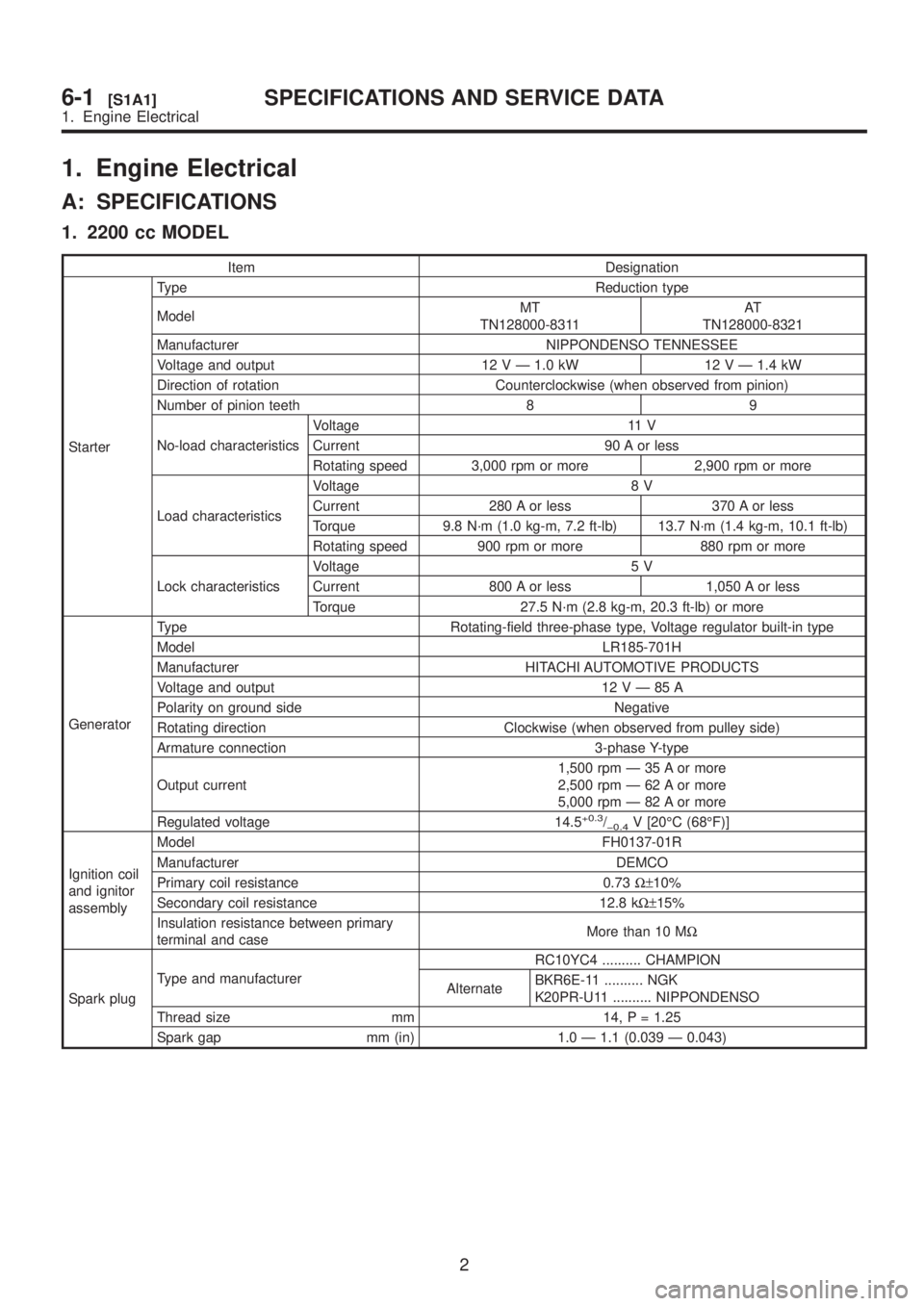
1. Engine Electrical
A: SPECIFICATIONS
1. 2200 cc MODEL
Item Designation
StarterType Reduction type
ModelMT
TN128000-8311AT
TN128000-8321
Manufacturer NIPPONDENSO TENNESSEE
Voltage and output 12 V Ð 1.0 kW 12 V Ð 1.4 kW
Direction of rotation Counterclockwise (when observed from pinion)
Number of pinion teeth 8 9
No-load characteristicsVoltage 11 V
Current 90 A or less
Rotating speed 3,000 rpm or more 2,900 rpm or more
Load characteristicsVoltage 8 V
Current 280 A or less 370 A or less
Torque 9.8 N´m (1.0 kg-m, 7.2 ft-lb) 13.7 N´m (1.4 kg-m, 10.1 ft-lb)
Rotating speed 900 rpm or more 880 rpm or more
Lock characteristicsVoltage 5 V
Current 800 A or less 1,050 A or less
Torque 27.5 N´m (2.8 kg-m, 20.3 ft-lb) or more
GeneratorType Rotating-field three-phase type, Voltage regulator built-in type
Model LR185-701H
Manufacturer HITACHI AUTOMOTIVE PRODUCTS
Voltage and output 12VÐ85A
Polarity on ground side Negative
Rotating direction Clockwise (when observed from pulley side)
Armature connection 3-phase Y-type
Output current1,500 rpm Ð 35 A or more
2,500 rpm Ð 62 A or more
5,000 rpm Ð 82 A or more
Regulated voltage 14.5
+0.3/þ0.4V [20ÉC (68ÉF)]
Ignition coil
and ignitor
assemblyModel FH0137-01R
Manufacturer DEMCO
Primary coil resistance 0.73W±10%
Secondary coil resistance 12.8 kW±15%
Insulation resistance between primary
terminal and caseMore than 10 MW
Spark plugType and manufacturerRC10YC4 .......... CHAMPION
AlternateBKR6E-11 .......... NGK
K20PR-U11 .......... NIPPONDENSO
Thread size mm 14, P = 1.25
Spark gap mm (in) 1.0 Ð 1.1 (0.039 Ð 0.043)
2
6-1[S1A1]SPECIFICATIONS AND SERVICE DATA
1. Engine Electrical
Page 1184 of 1456
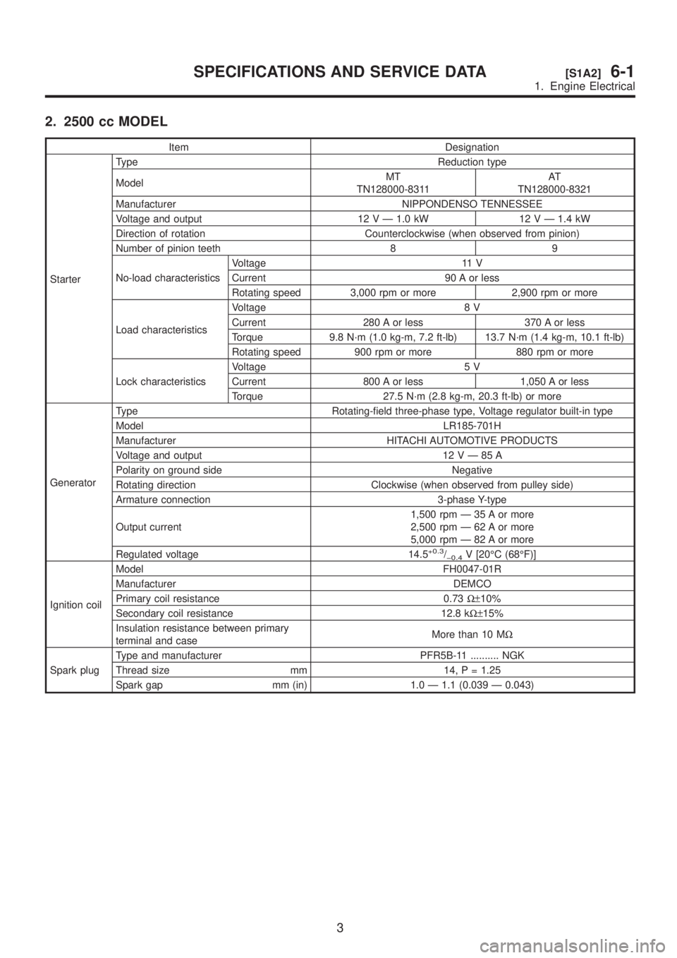
2. 2500 cc MODEL
Item Designation
StarterType Reduction type
ModelMT
TN128000-8311AT
TN128000-8321
Manufacturer NIPPONDENSO TENNESSEE
Voltage and output 12 V Ð 1.0 kW 12 V Ð 1.4 kW
Direction of rotation Counterclockwise (when observed from pinion)
Number of pinion teeth 8 9
No-load characteristicsVoltage 11 V
Current 90 A or less
Rotating speed 3,000 rpm or more 2,900 rpm or more
Load characteristicsVoltage 8 V
Current 280 A or less 370 A or less
Torque 9.8 N´m (1.0 kg-m, 7.2 ft-lb) 13.7 N´m (1.4 kg-m, 10.1 ft-lb)
Rotating speed 900 rpm or more 880 rpm or more
Lock characteristicsVoltage 5 V
Current 800 A or less 1,050 A or less
Torque 27.5 N´m (2.8 kg-m, 20.3 ft-lb) or more
GeneratorType Rotating-field three-phase type, Voltage regulator built-in type
Model LR185-701H
Manufacturer HITACHI AUTOMOTIVE PRODUCTS
Voltage and output 12VÐ85A
Polarity on ground side Negative
Rotating direction Clockwise (when observed from pulley side)
Armature connection 3-phase Y-type
Output current1,500 rpm Ð 35 A or more
2,500 rpm Ð 62 A or more
5,000 rpm Ð 82 A or more
Regulated voltage 14.5
+0.3/þ0.4V [20ÉC (68ÉF)]
Ignition coilModel FH0047-01R
Manufacturer DEMCO
Primary coil resistance 0.73W±10%
Secondary coil resistance 12.8 kW±15%
Insulation resistance between primary
terminal and caseMore than 10 MW
Spark plugType and manufacturer PFR5B-11 .......... NGK
Thread size mm 14, P = 1.25
Spark gap mm (in) 1.0 Ð 1.1 (0.039 Ð 0.043)
3
[S1A2]6-1SPECIFICATIONS AND SERVICE DATA
1. Engine Electrical
Page 1185 of 1456
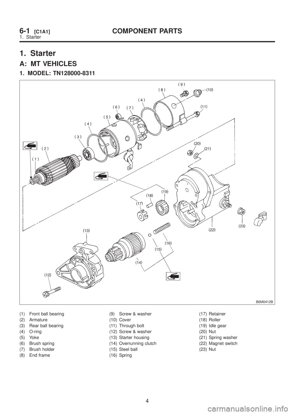
1. Starter
A: MT VEHICLES
1. MODEL: TN128000-8311
B6M0412B
(1) Front ball bearing
(2) Armature
(3) Rear ball bearing
(4) O-ring
(5) Yoke
(6) Brush spring
(7) Brush holder
(8) End frame(9) Screw & washer
(10) Cover
(11) Through bolt
(12) Screw & washer
(13) Starter housing
(14) Overrunning clutch
(15) Steel ball
(16) Spring(17) Retainer
(18) Roller
(19) Idle gear
(20) Nut
(21) Spring washer
(22) Magnet switch
(23) Nut
4
6-1[C1A1]COMPONENT PARTS
1. Starter
Page 1186 of 1456
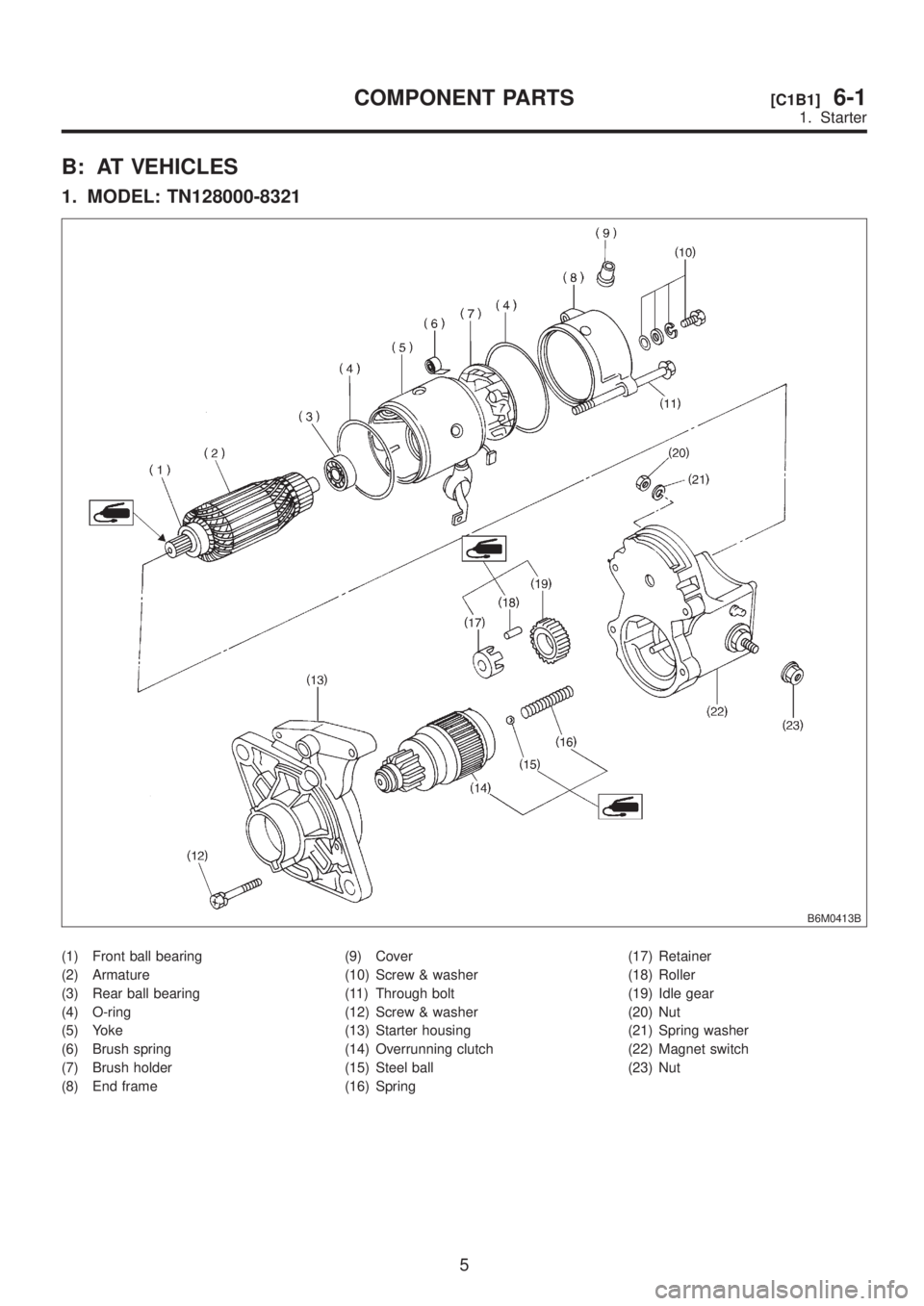
B: AT VEHICLES
1. MODEL: TN128000-8321
B6M0413B
(1) Front ball bearing
(2) Armature
(3) Rear ball bearing
(4) O-ring
(5) Yoke
(6) Brush spring
(7) Brush holder
(8) End frame(9) Cover
(10) Screw & washer
(11) Through bolt
(12) Screw & washer
(13) Starter housing
(14) Overrunning clutch
(15) Steel ball
(16) Spring(17) Retainer
(18) Roller
(19) Idle gear
(20) Nut
(21) Spring washer
(22) Magnet switch
(23) Nut
5
[C1B1]6-1COMPONENT PARTS
1. Starter
Page 1187 of 1456
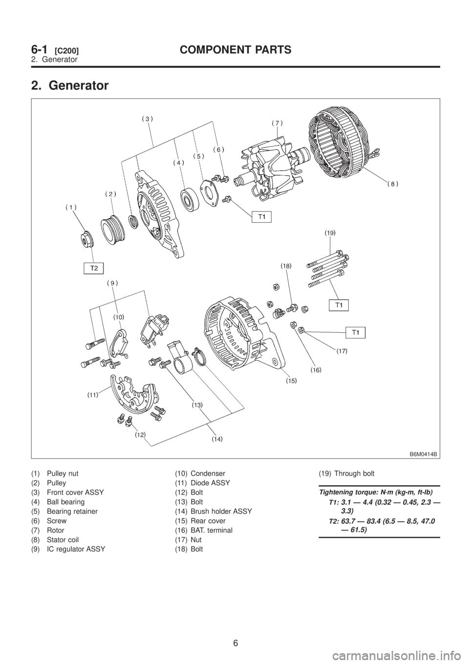
2. Generator
B6M0414B
(1) Pulley nut
(2) Pulley
(3) Front cover ASSY
(4) Ball bearing
(5) Bearing retainer
(6) Screw
(7) Rotor
(8) Stator coil
(9) IC regulator ASSY(10) Condenser
(11) Diode ASSY
(12) Bolt
(13) Bolt
(14) Brush holder ASSY
(15) Rear cover
(16) BAT. terminal
(17) Nut
(18) Bolt(19) Through bolt
Tightening torque: N´m (kg-m, ft-lb)
T1:
3.1 Ð 4.4 (0.32 Ð 0.45, 2.3 Ð
3.3)
T2:63.7 Ð 83.4 (6.5 Ð 8.5, 47.0
Ð 61.5)
6
6-1[C200]COMPONENT PARTS
2. Generator
Page 1188 of 1456
![SUBARU LEGACY 1999 Service Repair Manual 1. Starter
A: REMOVAL AND INSTALLATION
1) Disconnect battery ground cable.
B2M1723
2) Remove air intake chamber. <Ref. to 2-7
[W18A0].>
S6M0007
3) Remove air intake chamber stay. (AT vehicles
only)
S6 SUBARU LEGACY 1999 Service Repair Manual 1. Starter
A: REMOVAL AND INSTALLATION
1) Disconnect battery ground cable.
B2M1723
2) Remove air intake chamber. <Ref. to 2-7
[W18A0].>
S6M0007
3) Remove air intake chamber stay. (AT vehicles
only)
S6](/img/17/57435/w960_57435-1187.png)
1. Starter
A: REMOVAL AND INSTALLATION
1) Disconnect battery ground cable.
B2M1723
2) Remove air intake chamber.
S6M0007
3) Remove air intake chamber stay. (AT vehicles
only)
S6M0023
4) Remove bolt which installs hill holder cable
bracket. (2200 cc MT model with hill holder)
B6M0891
5) Disconnect connector and terminal from starter.
S6M0002A
(A) Terminal
(B) Connector
6) Remove starter from transmission.
G2M0309
7) Installation is in the reverse order of removal.
Tightening torque:
50
±4 N´m (5.1±0.4 kg-m, 37±2.9 ft-lb)
G2M0309
7
[W1A0]6-1SERVICE PROCEDURE
1. Starter
Page 1189 of 1456
B: TEST
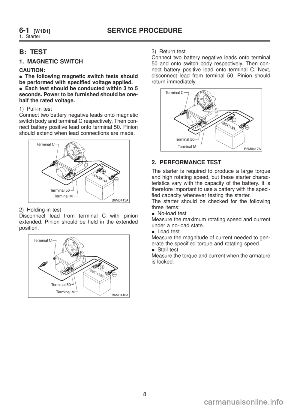
1. MAGNETIC SWITCH
CAUTION:
IThe following magnetic switch tests should
be performed with specified voltage applied.
IEach test should be conducted within 3 to 5
seconds. Power to be furnished should be one-
half the rated voltage.
1) Pull-in test
Connect two battery negative leads onto magnetic
switch body and terminal C respectively. Then con-
nect battery positive lead onto terminal 50. Pinion
should extend when lead connections are made.
B6M0415A
2) Holding-in test
Disconnect lead from terminal C with pinion
extended. Pinion should be held in the extended
position.
B6M0416A
3) Return test
Connect two battery negative leads onto terminal
50 and onto switch body respectively. Then con-
nect battery positive lead onto terminal C. Next,
disconnect lead from terminal 50. Pinion should
return immediately.
B6M0417A
2. PERFORMANCE TEST
The starter is required to produce a large torque
and high rotating speed, but these starter charac-
teristics vary with the capacity of the battery. It is
therefore important to use a battery with the speci-
fied capacity whenever testing the starter.
The starter should be checked for the following
three items:
INo-load test
Measure the maximum rotating speed and current
under a no-load state.
ILoad test
Measure the magnitude of current needed to gen-
erate the specified torque and rotating speed.
IStall test
Measure the torque and current when the armature
is locked.
8
6-1[W1B1]SERVICE PROCEDURE
1. Starter
Page 1190 of 1456
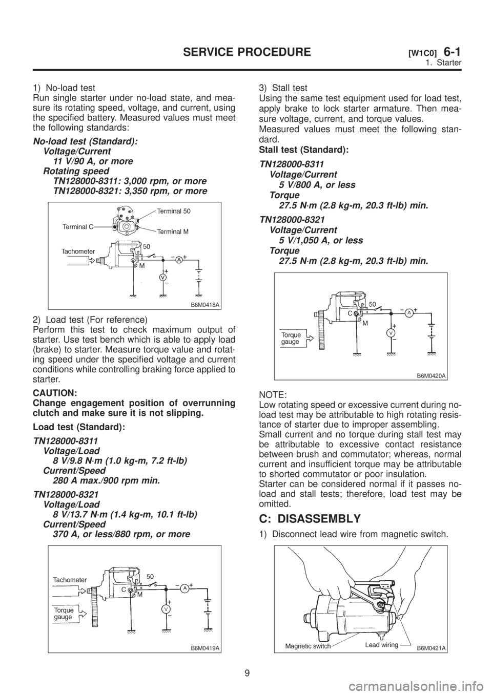
1) No-load test
Run single starter under no-load state, and mea-
sure its rotating speed, voltage, and current, using
the specified battery. Measured values must meet
the following standards:
No-load test (Standard):
Voltage/Current
11 V/90 A, or more
Rotating speed
TN128000-8311: 3,000 rpm, or more
TN128000-8321: 3,350 rpm, or more
B6M0418A
2) Load test (For reference)
Perform this test to check maximum output of
starter. Use test bench which is able to apply load
(brake) to starter. Measure torque value and rotat-
ing speed under the specified voltage and current
conditions while controlling braking force applied to
starter.
CAUTION:
Change engagement position of overrunning
clutch and make sure it is not slipping.
Load test (Standard):
TN128000-8311
Voltage/Load
8 V/9.8 N´m (1.0 kg-m, 7.2 ft-lb)
Current/Speed
280 A max./900 rpm min.
TN128000-8321
Voltage/Load
8 V/13.7 N´m (1.4 kg-m, 10.1 ft-lb)
Current/Speed
370 A, or less/880 rpm, or more
B6M0419A
3) Stall test
Using the same test equipment used for load test,
apply brake to lock starter armature. Then mea-
sure voltage, current, and torque values.
Measured values must meet the following stan-
dard.
Stall test (Standard):
TN128000-8311
Voltage/Current
5 V/800 A, or less
Torque
27.5 N´m (2.8 kg-m, 20.3 ft-lb) min.
TN128000-8321
Voltage/Current
5 V/1,050 A, or less
Torque
27.5 N´m (2.8 kg-m, 20.3 ft-lb) min.
B6M0420A
NOTE:
Low rotating speed or excessive current during no-
load test may be attributable to high rotating resis-
tance of starter due to improper assembling.
Small current and no torque during stall test may
be attributable to excessive contact resistance
between brush and commutator; whereas, normal
current and insufficient torque may be attributable
to shorted commutator or poor insulation.
Starter can be considered normal if it passes no-
load and stall tests; therefore, load test may be
omitted.
C: DISASSEMBLY
1) Disconnect lead wire from magnetic switch.
B6M0421A
9
[W1C0]6-1SERVICE PROCEDURE
1. Starter