SUBARU LEGACY 1999 Service Repair Manual
Manufacturer: SUBARU, Model Year: 1999, Model line: LEGACY, Model: SUBARU LEGACY 1999Pages: 1456, PDF Size: 59.93 MB
Page 1161 of 1456
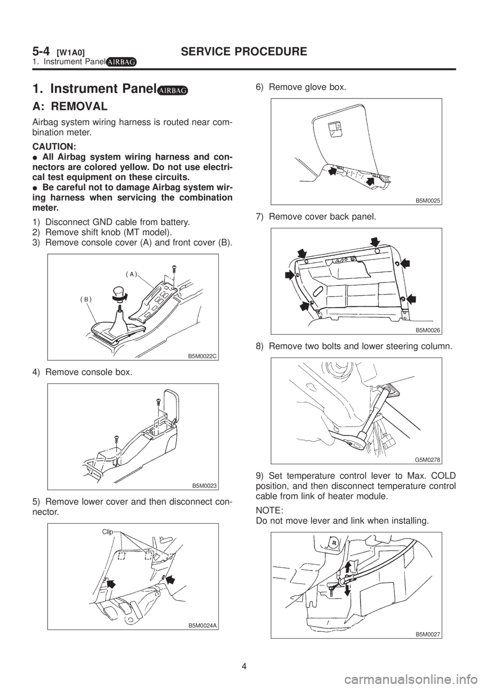
1. Instrument Panel
A: REMOVAL
Airbag system wiring harness is routed near com-
bination meter.
CAUTION:
IAll Airbag system wiring harness and con-
nectors are colored yellow. Do not use electri-
cal test equipment on these circuits.
IBe careful not to damage Airbag system wir-
ing harness when servicing the combination
meter.
1) Disconnect GND cable from battery.
2) Remove shift knob (MT model).
3) Remove console cover (A) and front cover (B).
B5M0022C
4) Remove console box.
B5M0023
5) Remove lower cover and then disconnect con-
nector.
B5M0024A
6) Remove glove box.
B5M0025
7) Remove cover back panel.
B5M0026
8) Remove two bolts and lower steering column.
G5M0278
9) Set temperature control lever to Max. COLD
position, and then disconnect temperature control
cable from link of heater module.
NOTE:
Do not move lever and link when installing.
B5M0027
4
5-4[W1A0]SERVICE PROCEDURE
1. Instrument Panel
Page 1162 of 1456
![SUBARU LEGACY 1999 Service Repair Manual 10) Remove bolt cover and bolt of both side.
B5M0028
11) Remove front side sill cover RH and then dis-
connect airbag connector (AB9) and (AB10) (Air-
bag model). <Ref. to 5-5 [M200].>
B5M0029A
12) Di SUBARU LEGACY 1999 Service Repair Manual 10) Remove bolt cover and bolt of both side.
B5M0028
11) Remove front side sill cover RH and then dis-
connect airbag connector (AB9) and (AB10) (Air-
bag model). <Ref. to 5-5 [M200].>
B5M0029A
12) Di](/img/17/57435/w960_57435-1161.png)
10) Remove bolt cover and bolt of both side.
B5M0028
11) Remove front side sill cover RH and then dis-
connect airbag connector (AB9) and (AB10) (Air-
bag model).
B5M0029A
12) Disconnect harness connectors and then remove the installing bolt.
CAUTION:
Be sure to hold socket section and not harness when disconnecting.
NOTE:
Put matching mark, if necessary, for easy re-assembly.
B5M0030B
(1) 15P/Gray
(2) 22P/Brown
(3) 22P/White(4) 20P/Blue
(5) 22P/Black
(6) 4P/Sky blue(7) 1P/Black
(8) 1P/Black
5
[W1A0]5-4SERVICE PROCEDURE
1. Instrument Panel
Page 1163 of 1456
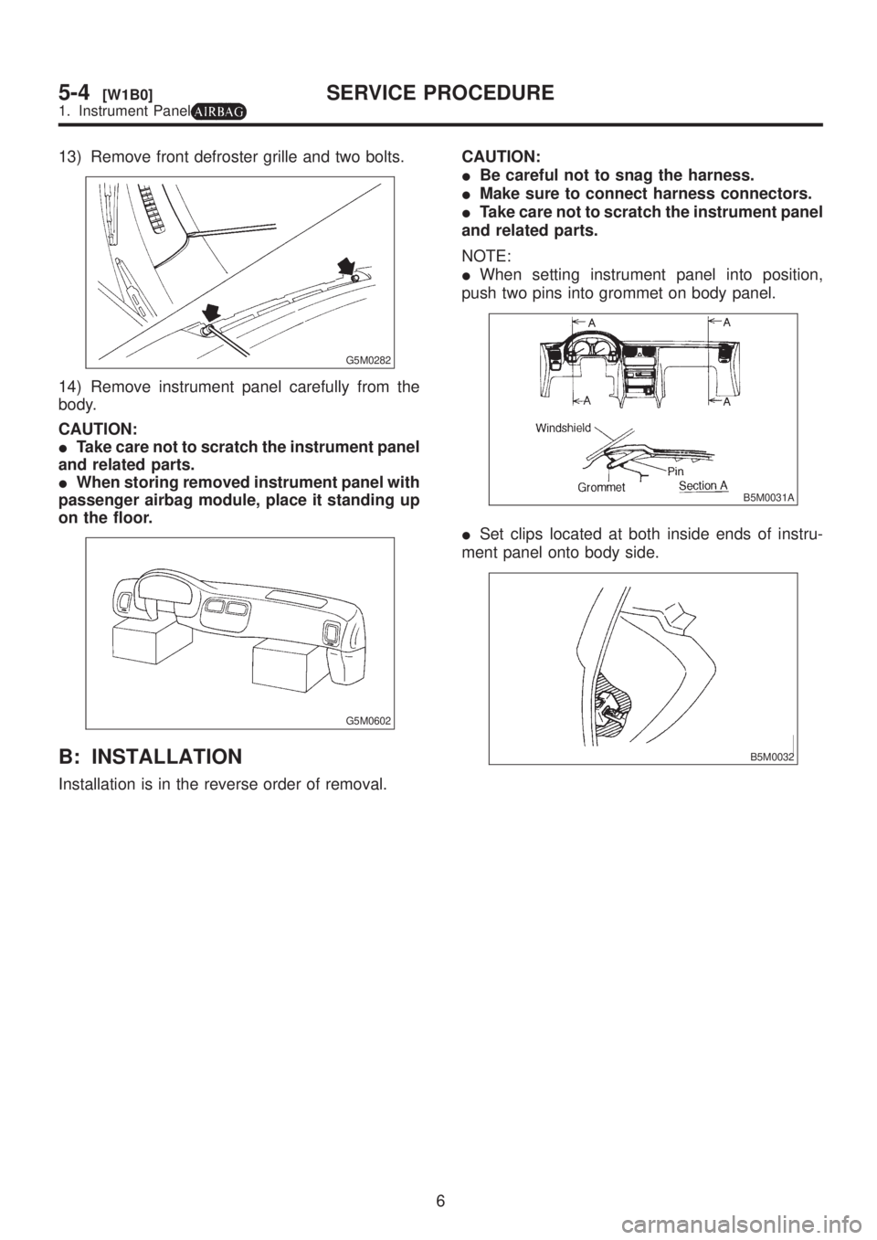
13) Remove front defroster grille and two bolts.
G5M0282
14) Remove instrument panel carefully from the
body.
CAUTION:
ITake care not to scratch the instrument panel
and related parts.
IWhen storing removed instrument panel with
passenger airbag module, place it standing up
on the floor.
G5M0602
B: INSTALLATION
Installation is in the reverse order of removal.CAUTION:
IBe careful not to snag the harness.
IMake sure to connect harness connectors.
ITake care not to scratch the instrument panel
and related parts.
NOTE:
IWhen setting instrument panel into position,
push two pins into grommet on body panel.
B5M0031A
ISet clips located at both inside ends of instru-
ment panel onto body side.
B5M0032
6
5-4[W1B0]SERVICE PROCEDURE
1. Instrument Panel
Page 1164 of 1456
![SUBARU LEGACY 1999 Service Repair Manual 1. SRS Airbag
B5M0513A
2
5-5[C100]COMPONENT PARTS
1. SRS Airbag SUBARU LEGACY 1999 Service Repair Manual 1. SRS Airbag
B5M0513A
2
5-5[C100]COMPONENT PARTS
1. SRS Airbag](/img/17/57435/w960_57435-1163.png)
1. SRS Airbag
B5M0513A
2
5-5[C100]COMPONENT PARTS
1. SRS Airbag
Page 1165 of 1456
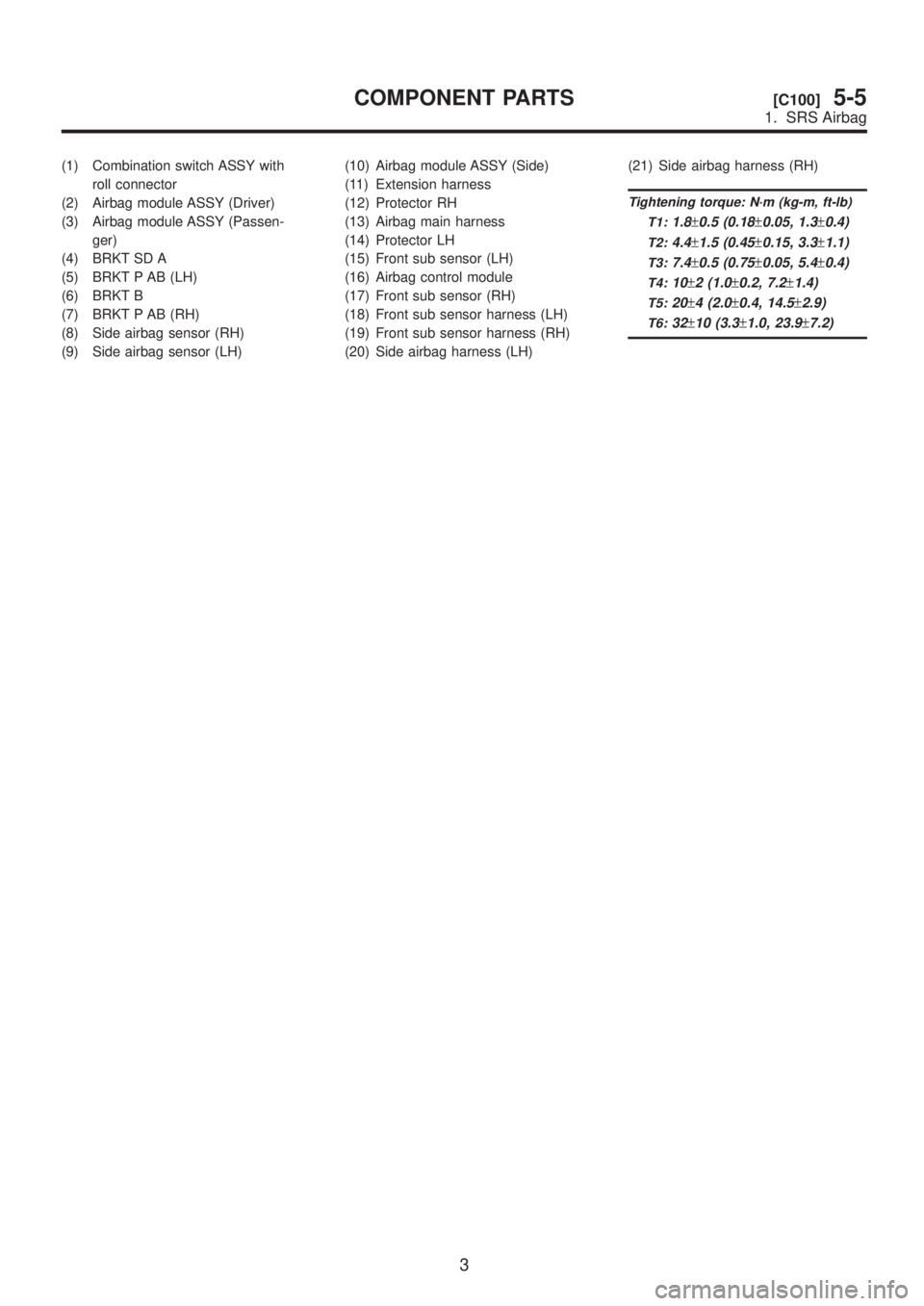
(1) Combination switch ASSY with
roll connector
(2) Airbag module ASSY (Driver)
(3) Airbag module ASSY (Passen-
ger)
(4) BRKT SD A
(5) BRKT P AB (LH)
(6) BRKT B
(7) BRKT P AB (RH)
(8) Side airbag sensor (RH)
(9) Side airbag sensor (LH)(10) Airbag module ASSY (Side)
(11) Extension harness
(12) Protector RH
(13) Airbag main harness
(14) Protector LH
(15) Front sub sensor (LH)
(16) Airbag control module
(17) Front sub sensor (RH)
(18) Front sub sensor harness (LH)
(19) Front sub sensor harness (RH)
(20) Side airbag harness (LH)(21) Side airbag harness (RH)
Tightening torque: N´m (kg-m, ft-lb)
T1:
1.8±0.5 (0.18±0.05, 1.3±0.4)
T2:4.4±1.5 (0.45±0.15, 3.3±1.1)
T3:7.4±0.5 (0.75±0.05, 5.4±0.4)
T4:10±2 (1.0±0.2, 7.2±1.4)
T5:20±4 (2.0±0.4, 14.5±2.9)
T6:32±10 (3.3±1.0, 23.9±7.2)
3
[C100]5-5COMPONENT PARTS
1. SRS Airbag
Page 1166 of 1456
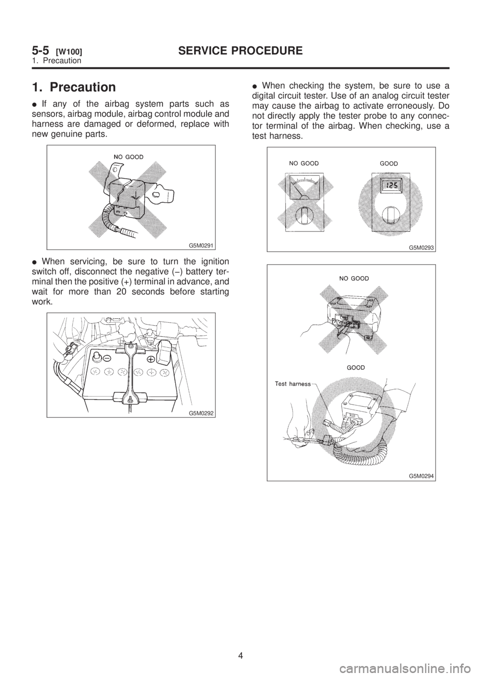
1. Precaution
IIf any of the airbag system parts such as
sensors, airbag module, airbag control module and
harness are damaged or deformed, replace with
new genuine parts.
G5M0291
IWhen servicing, be sure to turn the ignition
switch off, disconnect the negative (þ) battery ter-
minal then the positive (+) terminal in advance, and
wait for more than 20 seconds before starting
work.
G5M0292
IWhen checking the system, be sure to use a
digital circuit tester. Use of an analog circuit tester
may cause the airbag to activate erroneously. Do
not directly apply the tester probe to any connec-
tor terminal of the airbag. When checking, use a
test harness.
G5M0293
G5M0294
4
5-5[W100]SERVICE PROCEDURE
1. Precaution
Page 1167 of 1456
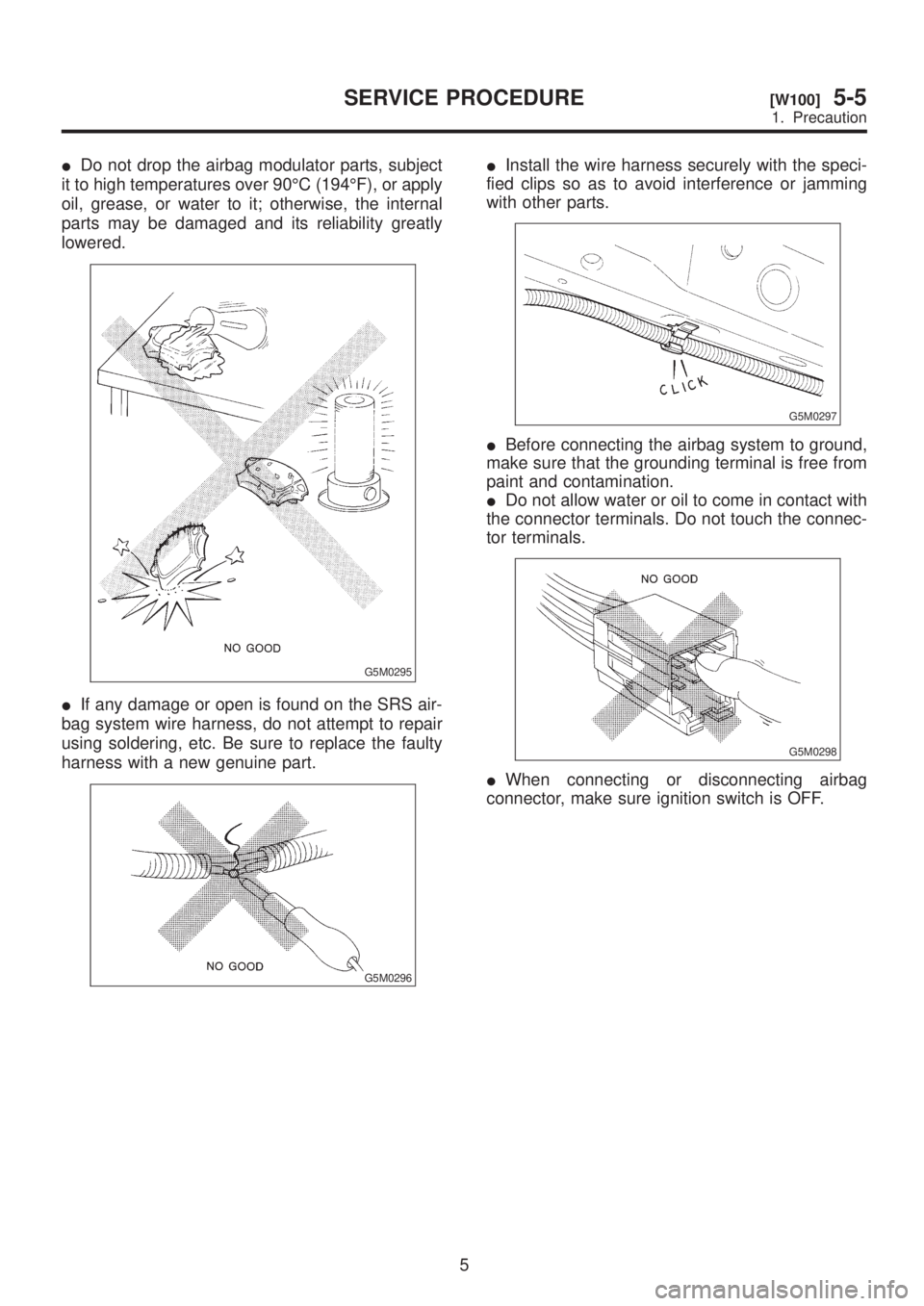
IDo not drop the airbag modulator parts, subject
it to high temperatures over 90ÉC (194ÉF), or apply
oil, grease, or water to it; otherwise, the internal
parts may be damaged and its reliability greatly
lowered.
G5M0295
IIf any damage or open is found on the SRS air-
bag system wire harness, do not attempt to repair
using soldering, etc. Be sure to replace the faulty
harness with a new genuine part.
G5M0296
IInstall the wire harness securely with the speci-
fied clips so as to avoid interference or jamming
with other parts.
G5M0297
IBefore connecting the airbag system to ground,
make sure that the grounding terminal is free from
paint and contamination.
IDo not allow water or oil to come in contact with
the connector terminals. Do not touch the connec-
tor terminals.
G5M0298
IWhen connecting or disconnecting airbag
connector, make sure ignition switch is OFF.
5
[W100]5-5SERVICE PROCEDURE
1. Precaution
Page 1168 of 1456
2. Inspection and Replacement
Standards
A: VEHICLES WHICH BECOME
INVOLVED IN A COLLISION
If the vehicle equipped with an SRS airbag sys-
tem is damaged in a collision, the airbag sys-
tem parts must be checked and replaced in
accordance with the following standards:
IAfter faulty parts are replaced, the warning light
operation must be checked.
IWhen the ignition switch is turned ON, it lights
up for about 7 seconds and then it goes out for at
least 30 seconds.
IThe trouble code stored in memory must be
erased after the check.
B: AIRBAG MODULE (DRIVER AND
PASSENGER)
1. INSPECTION STANDARD
IThe vehicle damaged in a frontal collision
(regardless of whether or not airbag is deployed).
IThe designated trouble code is output during
self-diagnosis.
2. REPLACEMENT STANDARD
IAirbag is deployed.
IThe pad surface is scratched or cracked.
IHarness and/or connector is deformed or
cracked, their circuits are broken, lead wire is
exposed, etc.
IMounting bracket is cracked or deformed.
IThe module surface is fouled with foreign mat-
ter. (grease, oil, water, cleaning solvent, etc.)
IAirbag module dropped to the floor/ground.
IAirbag module determined as faulty during self-
diagnosis.
C: AIRBAG MODULE (SIDE)
1. INSPECTION STANDARD
IThe vehicle damaged in a side collision (regard-
less of whether or not airbag is deployed).
IThe designated trouble code is output during
self-diagnosis.
2. REPLACEMENT STANDARD
IAirbag is deployed.
IThe front seat assembly is dameged or
deformed.
IHarness and/or connector is deformed or
cracked, their circuits are broken, lead wire is
exposed, etc.
IMounting bracket is cracked or deformed.IAirbag module determined as faulty during self-
diagnosis.
D: MAIN HARNESS
1. INSPECTION STANDARD
IA vehicle damaged in a collision (regardless of
whether or not airbag is deployed).
IThe designated trouble code is output during
self-diagnosis.
2. REPLACEMENT STANDARD
IHarness circuit is broken, lead wire is exposed,
corrugated tube is cracked, etc.
IConnector is scratched or cracked.
IThe designated trouble code is output during
self-diagnosis.
E: AIRBAG CONTROL MODULE
1. INSPECTION STANDARD
IA vehicle damaged in a collision (regardless of
whether or not airbag is deployed).
IThe designated trouble code is output during
self-diagnosis.
2. REPLACEMENT STANDARD
IControl module is cracked or deformed.
IMounting bracket is cracked or deformed.
IConnector is scratched or cracked.
IControl module dropped to the floor/ground.
IControl module determined as faulty during
diagnostics.
IAirbag is deployed.
F: COMBINATION SWITCH
1. INSPECTION STANDARD
IA vehicle damaged in a collision (regardless of
whether or not airbag is deployed).
IThe designated trouble code is output during
self-diagnosis.
2. REPLACEMENT STANDARD
Combination switch or steering roll connector is
deformed or cracked.
6
5-5[W2A0]SERVICE PROCEDURE
2. Inspection and Replacement Standards
Page 1169 of 1456
G: STEERING WHEEL
1. INSPECTION STANDARD
A vehicle damaged in a collision (regardless of
whether or not airbag is deployed).
2. REPLACEMENT STANDARD
ICheck steering wheel insert for cracks or defor-
mities.
ICheck to ensure that new airbag module is prop-
erly installed in steering wheel.
IAfter installing airbag module, check to ensure
that it is free of interference with steering wheel
and that clearance between the two is equal at all
points.
B5M0095
H: STEERING COLUMN ASSEMBLY
1. INSPECTION STANDARD
A vehicle damaged in a collision (regardless of
whether or not airbag is deployed).
2. REPLACEMENT STANDARD
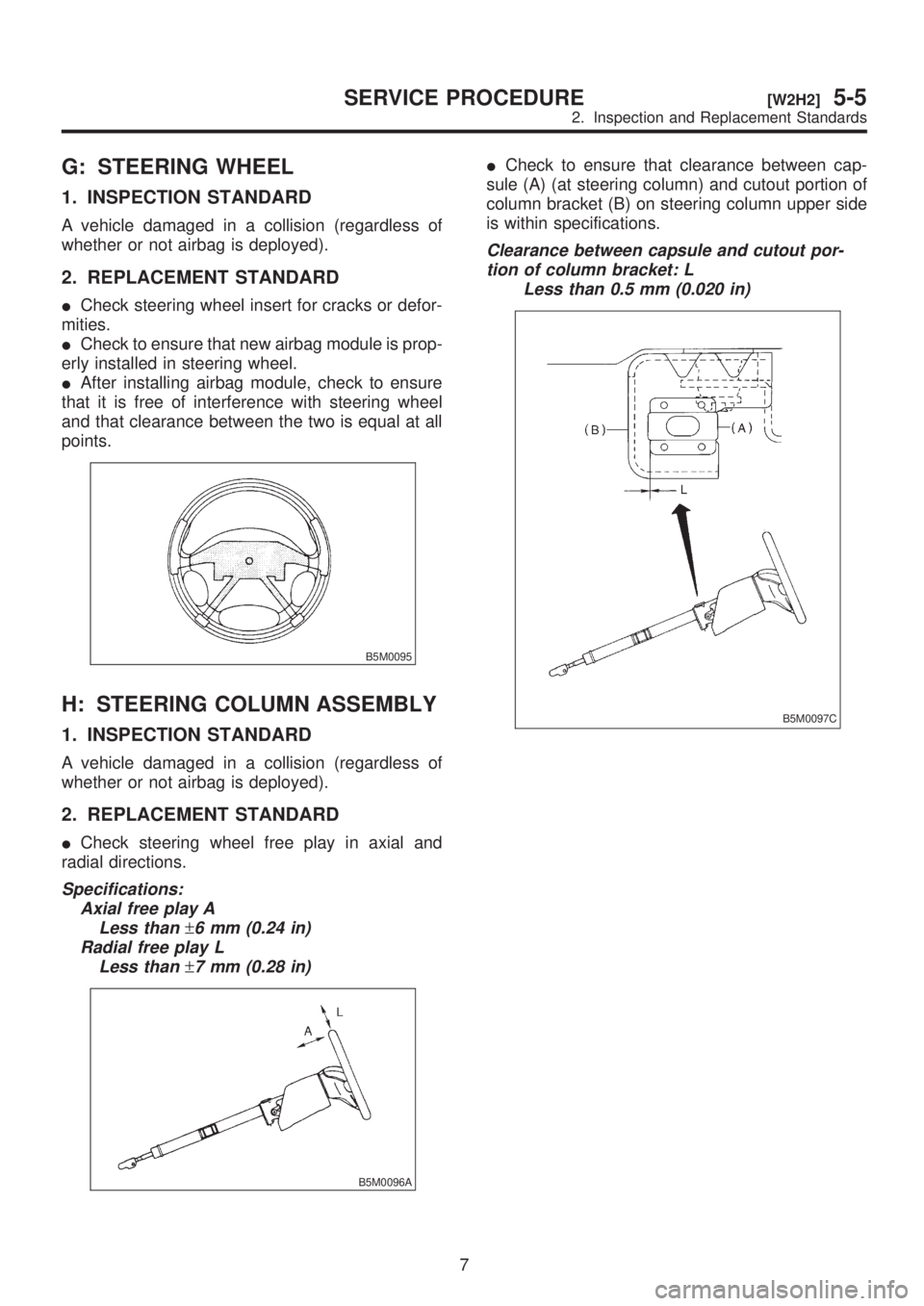
ICheck steering wheel free play in axial and
radial directions.
Specifications:
Axial free play A
Less than
±6 mm (0.24 in)
Radial free play L
Less than
±7 mm (0.28 in)
B5M0096A
ICheck to ensure that clearance between cap-
sule (A) (at steering column) and cutout portion of
column bracket (B) on steering column upper side
is within specifications.
Clearance between capsule and cutout por-
tion of column bracket: L
Less than 0.5 mm (0.020 in)
B5M0097C
7
[W2H2]5-5SERVICE PROCEDURE
2. Inspection and Replacement Standards
Page 1170 of 1456
I: FRONT SUB SENSOR
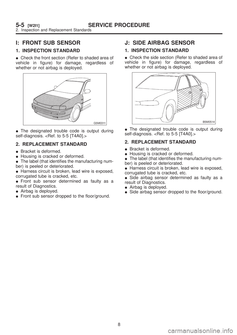
1. INSPECTION STANDARD
ICheck the front section (Refer to shaded area of
vehicle in figure) for damage, regardless of
whether or not airbag is deployed.
G5M0311
IThe designated trouble code is output during
self-diagnosis.
2. REPLACEMENT STANDARD
IBracket is deformed.
IHousing is cracked or deformed.
IThe label (that identifies the manufacturing num-
ber) is peeled or deteriorated.
IHarness circuit is broken, lead wire is exposed,
corrugated tube is cracked, etc.
IFront sub sensor determined as faulty as a
result of Diagnostics.
IAirbag is deployed.
IFront sub sensor dropped to the floor/ground.
J: SIDE AIRBAG SENSOR
1. INSPECTION STANDARD
ICheck the side section (Refer to shaded area of
vehicle in figure) for damage, regardless of
whether or not airbag is deployed.
B5M0514
IThe designated trouble code is output during
self-diagnosis.
2. REPLACEMENT STANDARD
IBracket is deformed.
IHousing is cracked or deformed.
IThe label (that identifies the manufacturing num-
ber) is peeled or deteriorated.
IHarness circuit is broken, lead wire is exposed,
corrugated tube is cracked, etc.
ISide airbag sensor determined as faulty as a
result of Diagnostics.
IAirbag is deployed.
ISide airbag sensor dropped to the floor/ground.
8
5-5[W2I1]SERVICE PROCEDURE
2. Inspection and Replacement Standards