wheel SUBARU LEGACY 1999 Service Repair Manual
[x] Cancel search | Manufacturer: SUBARU, Model Year: 1999, Model line: LEGACY, Model: SUBARU LEGACY 1999Pages: 1456, PDF Size: 59.93 MB
Page 795 of 1456
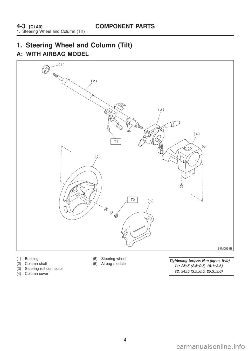
1. Steering Wheel and Column (Tilt)
A: WITH AIRBAG MODEL
B4M0551B
(1) Bushing
(2) Column shaft
(3) Steering roll connector
(4) Column cover(5) Steering wheel
(6) Airbag moduleTightening torque: N´m (kg-m, ft-lb)
T1:
25±5 (2.5±0.5, 18.1±3.6)
T2:34±5 (3.5±0.5, 25.3±3.6)
4
4-3[C1A0]COMPONENT PARTS
1. Steering Wheel and Column (Tilt)
Page 801 of 1456
1. Supplemental Restraint
System ªAirbagº
A: PRECAUTION
Airbag system wiring harness is routed near the
steering wheel, steering shaft and column.
WARNING:
IAll Airbag system wiring harness and con-
nectors are colored yellow. Do not use electri-cal test equipment on these circuit.
IBe careful not to damage Airbag system wir-
ing harness when servicing the steering wheel,
steering shaft and column.
10
4-3[W1A0]SERVICE PROCEDURE
1. Supplemental Restraint System ªAirbagº
Page 802 of 1456
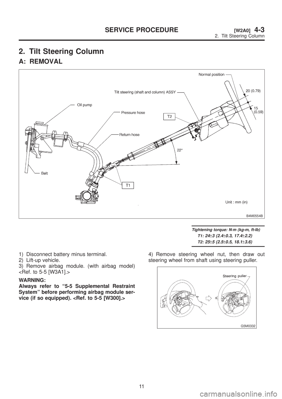
2. Tilt Steering Column
A: REMOVAL
B4M0554B
Tightening torque: N´m (kg-m, ft-lb)
T1:
24±3 (2.4±0.3, 17.4±2.2)
T2:25±5 (2.5±0.5, 18.1±3.6)
1) Disconnect battery minus terminal.
2) Lift-up vehicle.
3) Remove airbag module. (with airbag model)
WARNING:
Always refer to ª5-5 Supplemental Restraint
Systemº before performing airbag module ser-
vice (if so equipped).
steering wheel from shaft using steering puller.
G5M0332
11
[W2A0]4-3SERVICE PROCEDURE
2. Tilt Steering Column
Page 804 of 1456
Part name Inspection Corrective action
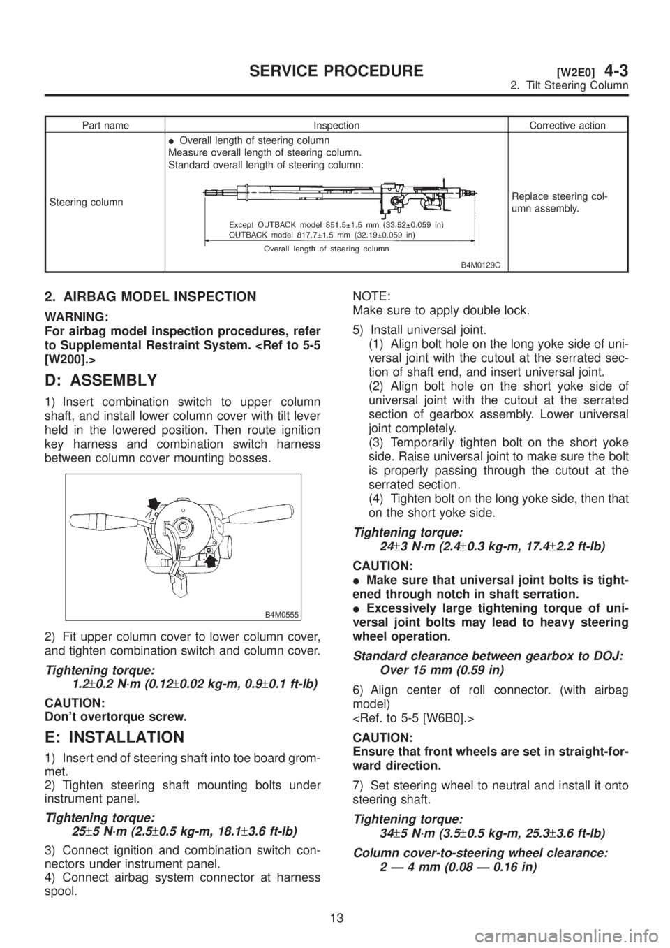
Steering columnIOverall length of steering column
Measure overall length of steering column.
Standard overall length of steering column:
B4M0129C
Replace steering col-
umn assembly.
2. AIRBAG MODEL INSPECTION
WARNING:
For airbag model inspection procedures, refer
to Supplemental Restraint System.
[W200].>
D: ASSEMBLY
1) Insert combination switch to upper column
shaft, and install lower column cover with tilt lever
held in the lowered position. Then route ignition
key harness and combination switch harness
between column cover mounting bosses.
B4M0555
2) Fit upper column cover to lower column cover,
and tighten combination switch and column cover.
Tightening torque:
1.2
±0.2 N´m (0.12±0.02 kg-m, 0.9±0.1 ft-lb)
CAUTION:
Don't overtorque screw.
E: INSTALLATION
1) Insert end of steering shaft into toe board grom-
met.
2) Tighten steering shaft mounting bolts under
instrument panel.
Tightening torque:
25
±5 N´m (2.5±0.5 kg-m, 18.1±3.6 ft-lb)
3) Connect ignition and combination switch con-
nectors under instrument panel.
4) Connect airbag system connector at harness
spool.NOTE:
Make sure to apply double lock.
5) Install universal joint.
(1) Align bolt hole on the long yoke side of uni-
versal joint with the cutout at the serrated sec-
tion of shaft end, and insert universal joint.
(2) Align bolt hole on the short yoke side of
universal joint with the cutout at the serrated
section of gearbox assembly. Lower universal
joint completely.
(3) Temporarily tighten bolt on the short yoke
side. Raise universal joint to make sure the bolt
is properly passing through the cutout at the
serrated section.
(4) Tighten bolt on the long yoke side, then that
on the short yoke side.
Tightening torque:
24
±3 N´m (2.4±0.3 kg-m, 17.4±2.2 ft-lb)
CAUTION:
IMake sure that universal joint bolts is tight-
ened through notch in shaft serration.
IExcessively large tightening torque of uni-
versal joint bolts may lead to heavy steering
wheel operation.
Standard clearance between gearbox to DOJ:
Over 15 mm (0.59 in)
6) Align center of roll connector. (with airbag
model)
CAUTION:
Ensure that front wheels are set in straight-for-
ward direction.
7) Set steering wheel to neutral and install it onto
steering shaft.
Tightening torque:
34
±5 N´m (3.5±0.5 kg-m, 25.3±3.6 ft-lb)
Column cover-to-steering wheel clearance:
2Ð4mm(0.08 Ð 0.16 in)
13
[W2E0]4-3SERVICE PROCEDURE
2. Tilt Steering Column
Page 805 of 1456
CAUTION:
Insert roll connector guide pin into guide hole
on lower end of surface of steering wheel to
prevent damage.
Draw out airbag system connector, horn con-
nector and cruise control connectors from
guide hole of steering wheel lower end. (with
airbag model)
8) Install airbag module to steering wheel. (with
airbag model)
WARNING:
Always refer to 5-5 Supplemental Restraint
System before performing the service opera-
tion.
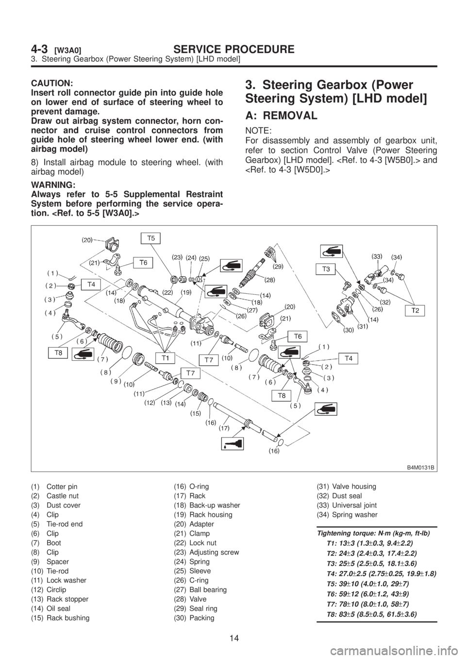
Steering System) [LHD model]
A: REMOVAL
NOTE:
For disassembly and assembly of gearbox unit,
refer to section Control Valve (Power Steering
Gearbox) [LHD model].
B4M0131B
(1) Cotter pin
(2) Castle nut
(3) Dust cover
(4) Clip
(5) Tie-rod end
(6) Clip
(7) Boot
(8) Clip
(9) Spacer
(10) Tie-rod
(11) Lock washer
(12) Circlip
(13) Rack stopper
(14) Oil seal
(15) Rack bushing(16) O-ring
(17) Rack
(18) Back-up washer
(19) Rack housing
(20) Adapter
(21) Clamp
(22) Lock nut
(23) Adjusting screw
(24) Spring
(25) Sleeve
(26) C-ring
(27) Ball bearing
(28) Valve
(29) Seal ring
(30) Packing(31) Valve housing
(32) Dust seal
(33) Universal joint
(34) Spring washer
Tightening torque: N´m (kg-m, ft-lb)
T1:
13±3 (1.3±0.3, 9.4±2.2)
T2:24±3 (2.4±0.3, 17.4±2.2)
T3:25±5 (2.5±0.5, 18.1±3.6)
T4:27.0±2.5 (2.75±0.25, 19.9±1.8)
T5:39±10 (4.0±1.0, 29±7)
T6:59±12 (6.0±1.2, 43±9)
T7:78±10 (8.0±1.0, 58±7)
T8:83±5 (8.5±0.5, 61.5±3.6)
14
4-3[W3A0]SERVICE PROCEDURE
3. Steering Gearbox (Power Steering System) [LHD model]
Page 806 of 1456
CAUTION:
Insert roll connector guide pin into guide hole
on lower end of surface of steering wheel to
prevent damage.
Draw out airbag system connector, horn con-
nector and cruise control connectors from
guide hole of steering wheel lower end. (with
airbag model)
8) Install airbag module to steering wheel. (with
airbag model)
WARNING:
Always refer to 5-5 Supplemental Restraint
System before performing the service opera-
tion.
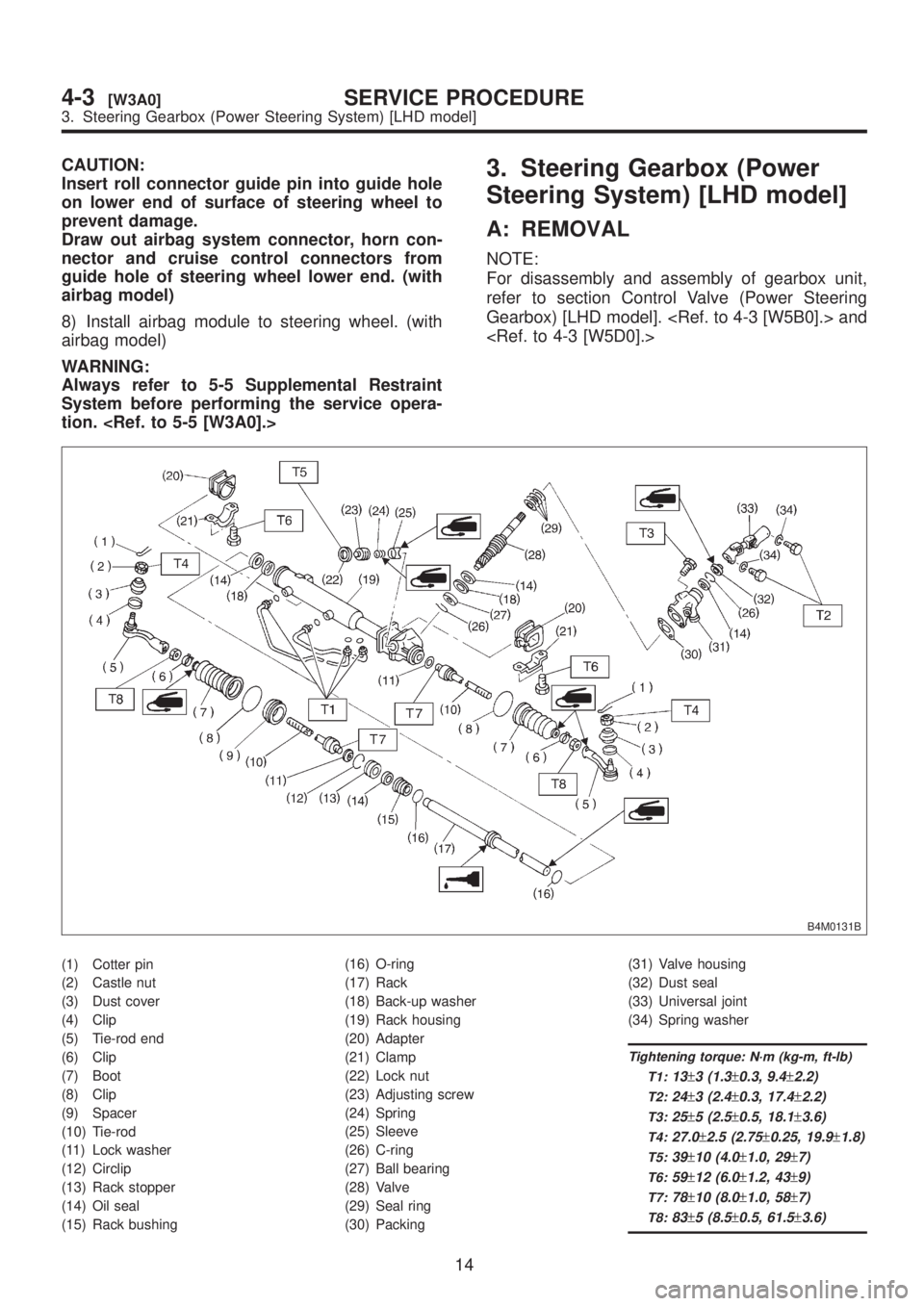
Steering System) [LHD model]
A: REMOVAL
NOTE:
For disassembly and assembly of gearbox unit,
refer to section Control Valve (Power Steering
Gearbox) [LHD model].
B4M0131B
(1) Cotter pin
(2) Castle nut
(3) Dust cover
(4) Clip
(5) Tie-rod end
(6) Clip
(7) Boot
(8) Clip
(9) Spacer
(10) Tie-rod
(11) Lock washer
(12) Circlip
(13) Rack stopper
(14) Oil seal
(15) Rack bushing(16) O-ring
(17) Rack
(18) Back-up washer
(19) Rack housing
(20) Adapter
(21) Clamp
(22) Lock nut
(23) Adjusting screw
(24) Spring
(25) Sleeve
(26) C-ring
(27) Ball bearing
(28) Valve
(29) Seal ring
(30) Packing(31) Valve housing
(32) Dust seal
(33) Universal joint
(34) Spring washer
Tightening torque: N´m (kg-m, ft-lb)
T1:
13±3 (1.3±0.3, 9.4±2.2)
T2:24±3 (2.4±0.3, 17.4±2.2)
T3:25±5 (2.5±0.5, 18.1±3.6)
T4:27.0±2.5 (2.75±0.25, 19.9±1.8)
T5:39±10 (4.0±1.0, 29±7)
T6:59±12 (6.0±1.2, 43±9)
T7:78±10 (8.0±1.0, 58±7)
T8:83±5 (8.5±0.5, 61.5±3.6)
14
4-3[W3A0]SERVICE PROCEDURE
3. Steering Gearbox (Power Steering System) [LHD model]
Page 807 of 1456
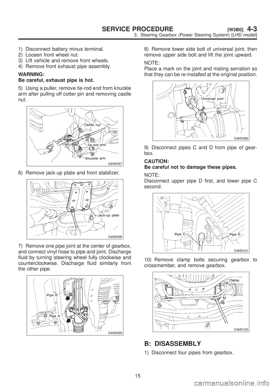
1) Disconnect battery minus terminal.
2) Loosen front wheel nut.
3) Lift vehicle and remove front wheels.
4) Remove front exhaust pipe assembly.
WARNING:
Be careful, exhaust pipe is hot.
5) Using a puller, remove tie-rod end from knuckle
arm after pulling off cotter pin and removing castle
nut.
G4M0097
6) Remove jack-up plate and front stabilizer.
G4M0098
7) Remove one pipe joint at the center of gearbox,
and connect vinyl hose to pipe and joint. Discharge
fluid by turning steering wheel fully clockwise and
counterclockwise. Discharge fluid similarly from
the other pipe.
G4M0099
8) Remove lower side bolt of universal joint, then
remove upper side bolt and lift the joint upward.
NOTE:
Place a mark on the joint and mating serration so
that they can be re-installed at the original position.
G4M0086
9) Disconnect pipes C and D from pipe of gear-
box.
CAUTION:
Be careful not to damage these pipes.
NOTE:
Disconnect upper pipe D first, and lower pipe C
second.
G4M0101
10) Remove clamp bolts securing gearbox to
crossmember, and remove gearbox.
G4M0102
B: DISASSEMBLY
1) Disconnect four pipes from gearbox.
15
[W3B0]4-3SERVICE PROCEDURE
3. Steering Gearbox (Power Steering System) [LHD model]
Page 813 of 1456
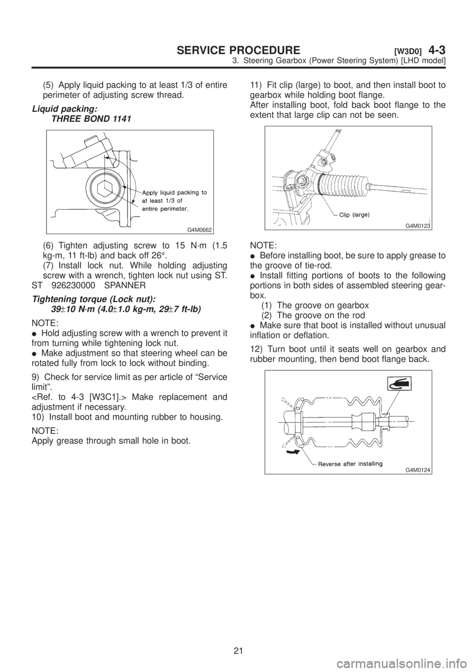
(5) Apply liquid packing to at least 1/3 of entire
perimeter of adjusting screw thread.
Liquid packing:
THREE BOND 1141
G4M0662
(6) Tighten adjusting screw to 15 N´m (1.5
kg-m, 11 ft-lb) and back off 26É.
(7) Install lock nut. While holding adjusting
screw with a wrench, tighten lock nut using ST.
ST 926230000 SPANNER
Tightening torque (Lock nut):
39
±10 N´m (4.0±1.0 kg-m, 29±7 ft-lb)
NOTE:
IHold adjusting screw with a wrench to prevent it
from turning while tightening lock nut.
IMake adjustment so that steering wheel can be
rotated fully from lock to lock without binding.
9) Check for service limit as per article of ªService
limitº.
adjustment if necessary.
10) Install boot and mounting rubber to housing.
NOTE:
Apply grease through small hole in boot.11) Fit clip (large) to boot, and then install boot to
gearbox while holding boot flange.
After installing boot, fold back boot flange to the
extent that large clip can not be seen.
G4M0123
NOTE:
IBefore installing boot, be sure to apply grease to
the groove of tie-rod.
IInstall fitting portions of boots to the following
portions in both sides of assembled steering gear-
box.
(1) The groove on gearbox
(2) The groove on the rod
IMake sure that boot is installed without unusual
inflation or deflation.
12) Turn boot until it seats well on gearbox and
rubber mounting, then bend boot flange back.
G4M0124
21
[W3D0]4-3SERVICE PROCEDURE
3. Steering Gearbox (Power Steering System) [LHD model]
Page 815 of 1456
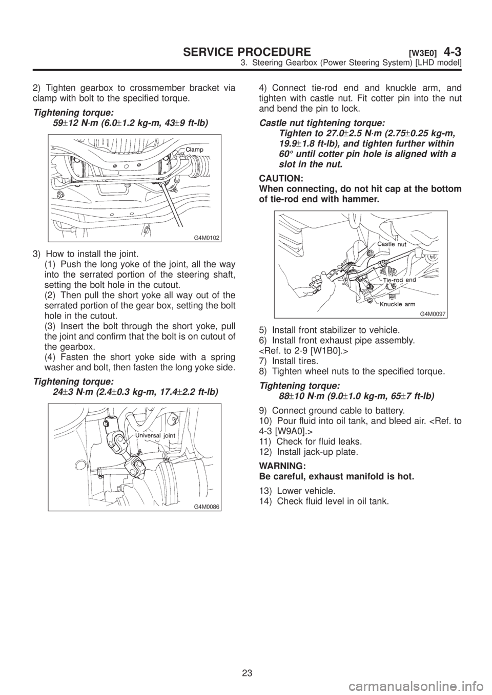
2) Tighten gearbox to crossmember bracket via
clamp with bolt to the specified torque.
Tightening torque:
59
±12 N´m (6.0±1.2 kg-m, 43±9 ft-lb)
G4M0102
3) How to install the joint.
(1) Push the long yoke of the joint, all the way
into the serrated portion of the steering shaft,
setting the bolt hole in the cutout.
(2) Then pull the short yoke all way out of the
serrated portion of the gear box, setting the bolt
hole in the cutout.
(3) Insert the bolt through the short yoke, pull
the joint and confirm that the bolt is on cutout of
the gearbox.
(4) Fasten the short yoke side with a spring
washer and bolt, then fasten the long yoke side.
Tightening torque:
24
±3 N´m (2.4±0.3 kg-m, 17.4±2.2 ft-lb)
G4M0086
4) Connect tie-rod end and knuckle arm, and
tighten with castle nut. Fit cotter pin into the nut
and bend the pin to lock.
Castle nut tightening torque:
Tighten to 27.0
±2.5 N´m (2.75±0.25 kg-m,
19.9
±1.8 ft-lb), and tighten further within
60É until cotter pin hole is aligned with a
slot in the nut.
CAUTION:
When connecting, do not hit cap at the bottom
of tie-rod end with hammer.
G4M0097
5) Install front stabilizer to vehicle.
6) Install front exhaust pipe assembly.
7) Install tires.
8) Tighten wheel nuts to the specified torque.
Tightening torque:
88
±10 N´m (9.0±1.0 kg-m, 65±7 ft-lb)
9) Connect ground cable to battery.
10) Pour fluid into oil tank, and bleed air.
11) Check for fluid leaks.
12) Install jack-up plate.
WARNING:
Be careful, exhaust manifold is hot.
13) Lower vehicle.
14) Check fluid level in oil tank.
23
[W3E0]4-3SERVICE PROCEDURE
3. Steering Gearbox (Power Steering System) [LHD model]
Page 816 of 1456
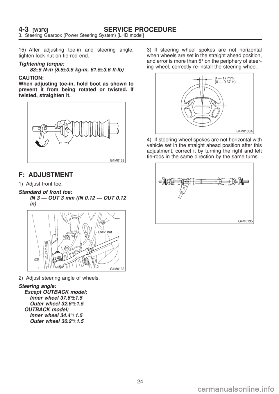
15) After adjusting toe-in and steering angle,
tighten lock nut on tie-rod end.
Tightening torque:
83
±5 N´m (8.5±0.5 kg-m, 61.5±3.6 ft-lb)
CAUTION:
When adjusting toe-in, hold boot as shown to
prevent it from being rotated or twisted. If
twisted, straighten it.
G4M0132
F: ADJUSTMENT
1) Adjust front toe.
Standard of front toe:
IN 3 Ð OUT 3 mm (IN 0.12 Ð OUT 0.12
in)
G4M0133
2) Adjust steering angle of wheels.
Steering angle:
Except OUTBACK model;
Inner wheel 37.6É
±1.5
Outer wheel 32.6É
±1.5
OUTBACK model;
Inner wheel 34.4É
±1.5
Outer wheel 30.2É
±1.5
3) If steering wheel spokes are not horizontal
when wheels are set in the straight ahead position,
and error is more than 5É on the periphery of steer-
ing wheel, correctly re-install the steering wheel.
B4M0133A
4) If steering wheel spokes are not horizontal with
vehicle set in the straight ahead position after this
adjustment, correct it by turning the right and left
tie-rods in the same direction by the same turns.
G4M0135
24
4-3[W3F0]SERVICE PROCEDURE
3. Steering Gearbox (Power Steering System) [LHD model]