wheel SUBARU LEGACY 1999 Service Owners Manual
[x] Cancel search | Manufacturer: SUBARU, Model Year: 1999, Model line: LEGACY, Model: SUBARU LEGACY 1999Pages: 1456, PDF Size: 59.93 MB
Page 782 of 1456
4. Replacement of Front SFJ,
DOJ and BJ Boots
A: REMOVAL
1) Disconnect ground cable from battery.
2) Jack-up vehicle, support it with safety stands
(rigid racks), and remove front wheel cap and
wheels.
NOTE:
Do not remove axle nut.
3) Remove stabilizer link.
4) Disconnect transverse link from housing.
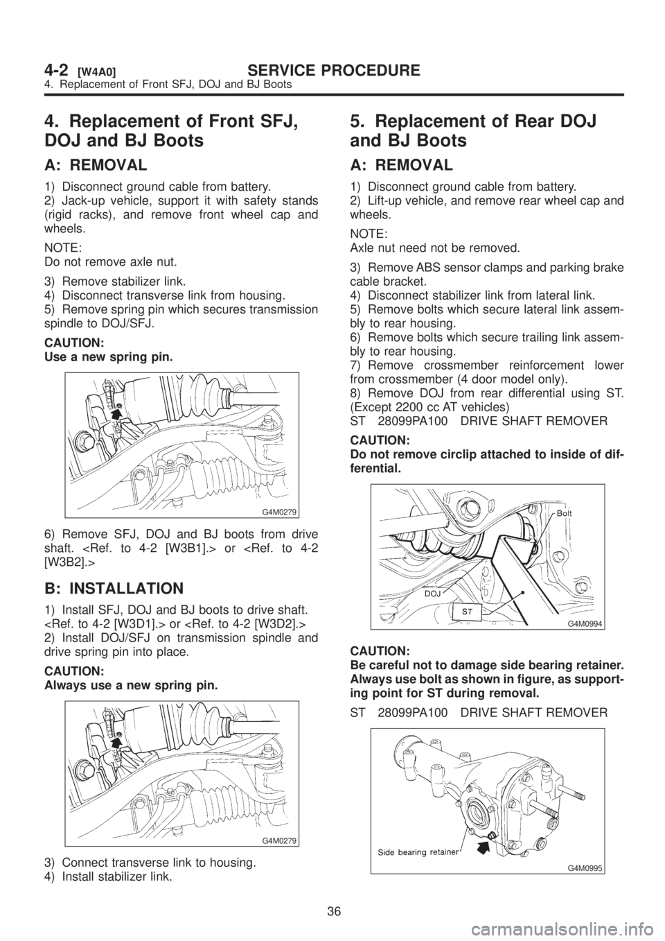
5) Remove spring pin which secures transmission
spindle to DOJ/SFJ.
CAUTION:
Use a new spring pin.
G4M0279
6) Remove SFJ, DOJ and BJ boots from drive
shaft.
B: INSTALLATION
1) Install SFJ, DOJ and BJ boots to drive shaft.
2) Install DOJ/SFJ on transmission spindle and
drive spring pin into place.
CAUTION:
Always use a new spring pin.
G4M0279
3) Connect transverse link to housing.
4) Install stabilizer link.
5. Replacement of Rear DOJ
and BJ Boots
A: REMOVAL
1) Disconnect ground cable from battery.
2) Lift-up vehicle, and remove rear wheel cap and
wheels.
NOTE:
Axle nut need not be removed.
3) Remove ABS sensor clamps and parking brake
cable bracket.
4) Disconnect stabilizer link from lateral link.
5) Remove bolts which secure lateral link assem-
bly to rear housing.
6) Remove bolts which secure trailing link assem-
bly to rear housing.
7) Remove crossmember reinforcement lower
from crossmember (4 door model only).
8) Remove DOJ from rear differential using ST.
(Except 2200 cc AT vehicles)
ST 28099PA100 DRIVE SHAFT REMOVER
CAUTION:
Do not remove circlip attached to inside of dif-
ferential.
G4M0994
CAUTION:
Be careful not to damage side bearing retainer.
Always use bolt as shown in figure, as support-
ing point for ST during removal.
ST 28099PA100 DRIVE SHAFT REMOVER
G4M0995
36
4-2[W4A0]SERVICE PROCEDURE
4. Replacement of Front SFJ, DOJ and BJ Boots
Page 783 of 1456
4. Replacement of Front SFJ,
DOJ and BJ Boots
A: REMOVAL
1) Disconnect ground cable from battery.
2) Jack-up vehicle, support it with safety stands
(rigid racks), and remove front wheel cap and
wheels.
NOTE:
Do not remove axle nut.
3) Remove stabilizer link.
4) Disconnect transverse link from housing.
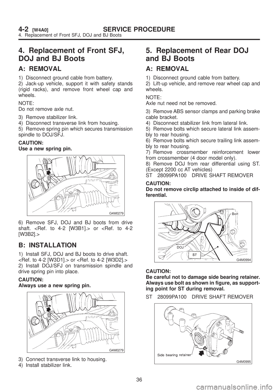
5) Remove spring pin which secures transmission
spindle to DOJ/SFJ.
CAUTION:
Use a new spring pin.
G4M0279
6) Remove SFJ, DOJ and BJ boots from drive
shaft.
B: INSTALLATION
1) Install SFJ, DOJ and BJ boots to drive shaft.
2) Install DOJ/SFJ on transmission spindle and
drive spring pin into place.
CAUTION:
Always use a new spring pin.
G4M0279
3) Connect transverse link to housing.
4) Install stabilizer link.
5. Replacement of Rear DOJ
and BJ Boots
A: REMOVAL
1) Disconnect ground cable from battery.
2) Lift-up vehicle, and remove rear wheel cap and
wheels.
NOTE:
Axle nut need not be removed.
3) Remove ABS sensor clamps and parking brake
cable bracket.
4) Disconnect stabilizer link from lateral link.
5) Remove bolts which secure lateral link assem-
bly to rear housing.
6) Remove bolts which secure trailing link assem-
bly to rear housing.
7) Remove crossmember reinforcement lower
from crossmember (4 door model only).
8) Remove DOJ from rear differential using ST.
(Except 2200 cc AT vehicles)
ST 28099PA100 DRIVE SHAFT REMOVER
CAUTION:
Do not remove circlip attached to inside of dif-
ferential.
G4M0994
CAUTION:
Be careful not to damage side bearing retainer.
Always use bolt as shown in figure, as support-
ing point for ST during removal.
ST 28099PA100 DRIVE SHAFT REMOVER
G4M0995
36
4-2[W4A0]SERVICE PROCEDURE
4. Replacement of Front SFJ, DOJ and BJ Boots
Page 785 of 1456
assembly, and tighten self-locking nut.
9) Connect stabilizer link to lateral link.
10) Install crossmember reinforcement lower to
crossmember (4 door model only).
11) Install ABS sensor clamps and parking brake
cable bracket.6. Full Wheel Cap
A: REMOVAL
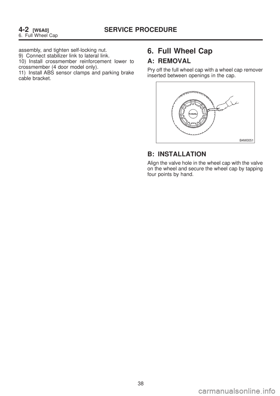
Pry off the full wheel cap with a wheel cap remover
inserted between openings in the cap.
B4M0051
B: INSTALLATION
Align the valve hole in the wheel cap with the valve
on the wheel and secure the wheel cap by tapping
four points by hand.
38
4-2[W6A0]SERVICE PROCEDURE
6. Full Wheel Cap
Page 786 of 1456
assembly, and tighten self-locking nut.
9) Connect stabilizer link to lateral link.
10) Install crossmember reinforcement lower to
crossmember (4 door model only).
11) Install ABS sensor clamps and parking brake
cable bracket.6. Full Wheel Cap
A: REMOVAL
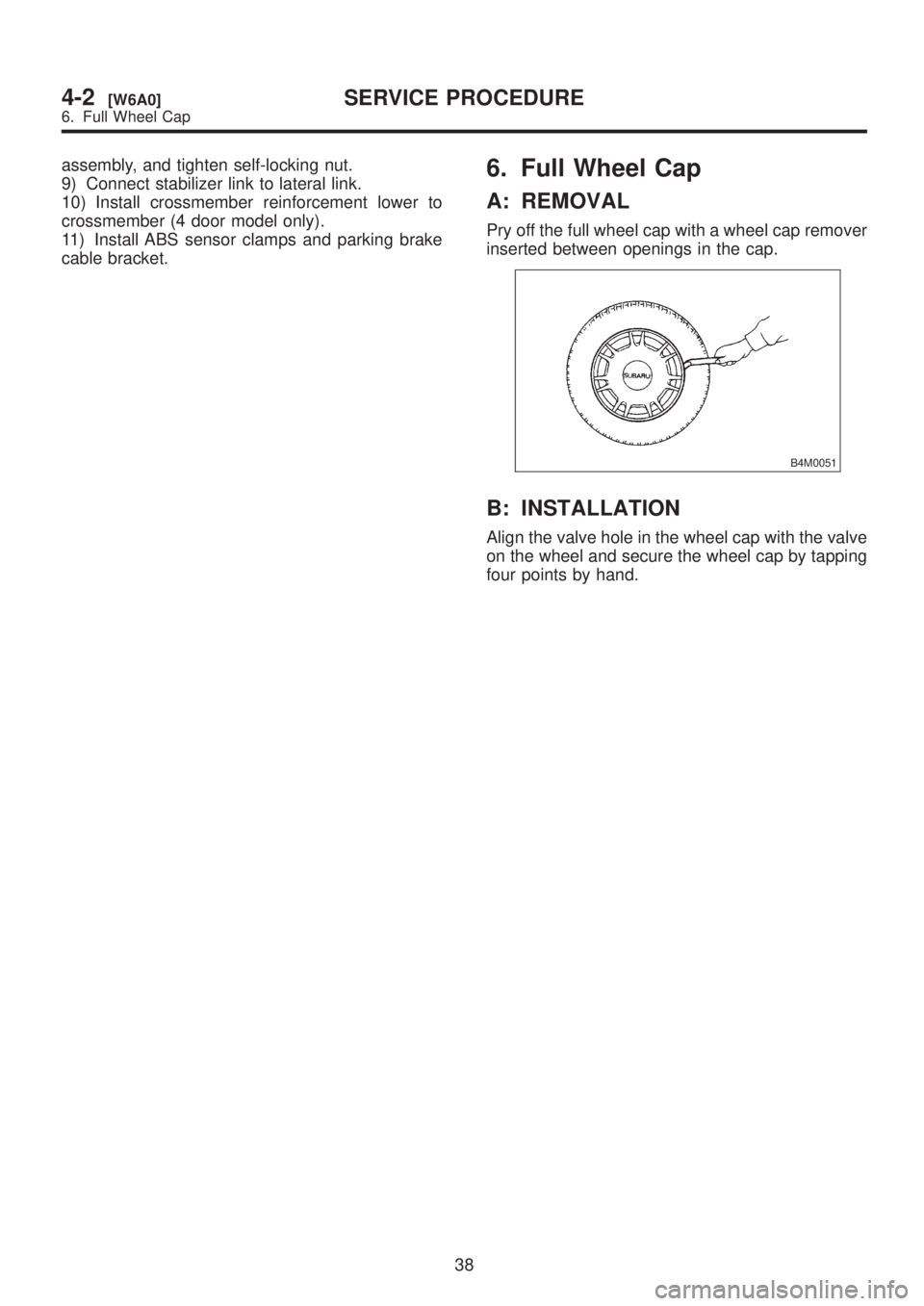
Pry off the full wheel cap with a wheel cap remover
inserted between openings in the cap.
B4M0051
B: INSTALLATION
Align the valve hole in the wheel cap with the valve
on the wheel and secure the wheel cap by tapping
four points by hand.
38
4-2[W6A0]SERVICE PROCEDURE
6. Full Wheel Cap
Page 787 of 1456
7. Steel Wheel and Tire
A: INSPECTION
1) Deformation or damage on the rim can cause
air leakage. Check the rim flange for deformation,
crack, or damage, and repair or replace as neces-
sary.
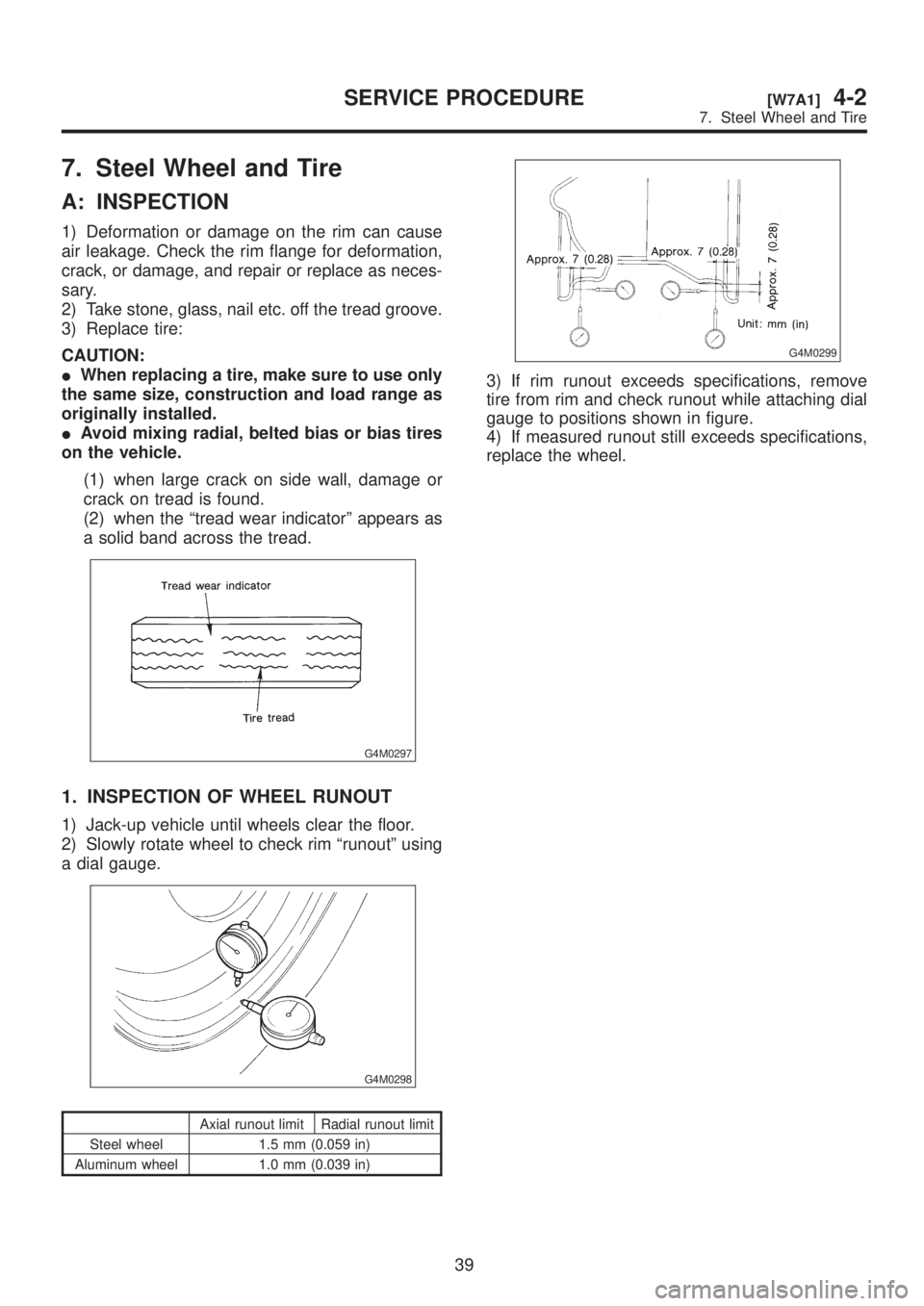
2) Take stone, glass, nail etc. off the tread groove.
3) Replace tire:
CAUTION:
IWhen replacing a tire, make sure to use only
the same size, construction and load range as
originally installed.
IAvoid mixing radial, belted bias or bias tires
on the vehicle.
(1) when large crack on side wall, damage or
crack on tread is found.
(2) when the ªtread wear indicatorº appears as
a solid band across the tread.
G4M0297
1. INSPECTION OF WHEEL RUNOUT
1) Jack-up vehicle until wheels clear the floor.
2) Slowly rotate wheel to check rim ªrunoutº using
a dial gauge.
G4M0298
Axial runout limit Radial runout limit
Steel wheel 1.5 mm (0.059 in)
Aluminum wheel 1.0 mm (0.039 in)
G4M0299
3) If rim runout exceeds specifications, remove
tire from rim and check runout while attaching dial
gauge to positions shown in figure.
4) If measured runout still exceeds specifications,
replace the wheel.
39
[W7A1]4-2SERVICE PROCEDURE
7. Steel Wheel and Tire
Page 788 of 1456
8. Aluminum Wheel
A: INSPECTION
Inspection for aluminum wheels is basically the
same as the one for steel wheels. However, check
the rim flange for cracks or damage, and replace
(not repair) aluminum wheel if air leakage is found.
B: PRECAUTIONS
Aluminum wheels are easily scratched. To main-
tain their appearance and safety, do the following:
1) Do not damage aluminum wheels during
removal, disassembly, installation, wheel
balancing, etc. After removing aluminum wheels,
place them on a rubber mat, etc.
2) While vehicle is being driven, be careful not to
ride over sharp obstacles or allow aluminum
wheels to contact the shoulder of the road.
3) When installing tire chain, be sure to install it
properly not to have a slack; otherwise it may hit
wheel while driving.
4) When washing aluminum wheel, use neutral
synthetic detergent and water. Avoid using the
cleanser including abrasive, hard brushes or an
automatic car washer.
9. Wheel Balancing
1) Proper wheel balance may be lost if the tire is
repaired or if it wears. Check the tire for dynamic
balance, and repair as necessary.
2) To check for dynamic balance, use a dynamic
balancer. Drive in the balance weight on both the
top and rear sides of the rim.
3) Some types of balancer can cause damage to
the wheel. Use an appropriate balancer when
adjusting the wheel balance.
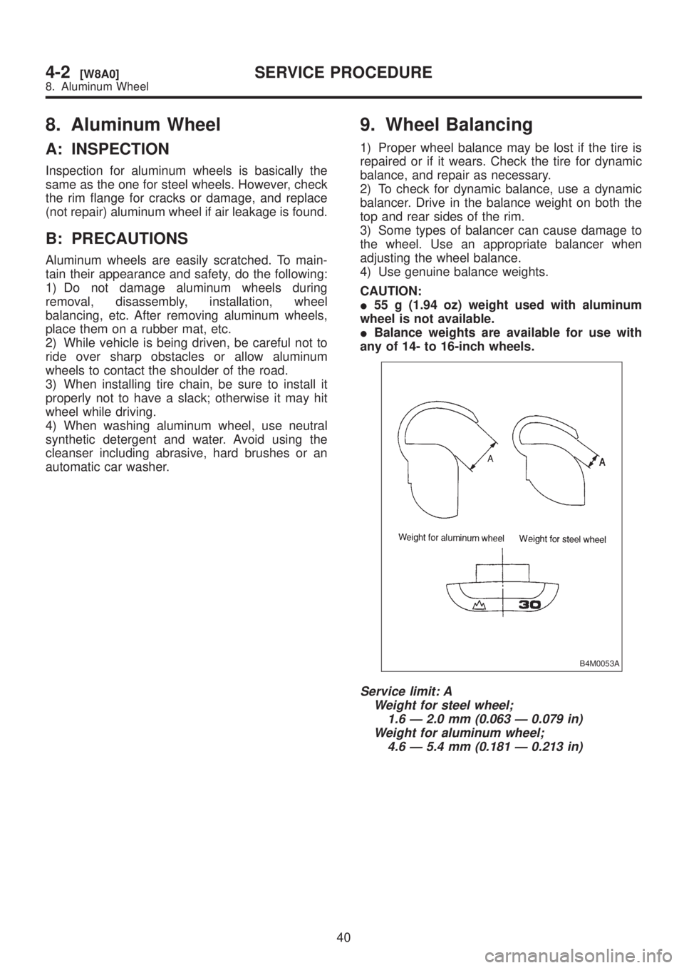
4) Use genuine balance weights.
CAUTION:
I55 g (1.94 oz) weight used with aluminum
wheel is not available.
IBalance weights are available for use with
any of 14- to 16-inch wheels.
B4M0053A
Service limit: A
Weight for steel wheel;
1.6 Ð 2.0 mm (0.063 Ð 0.079 in)
Weight for aluminum wheel;
4.6 Ð 5.4 mm (0.181 Ð 0.213 in)
40
4-2[W8A0]SERVICE PROCEDURE
8. Aluminum Wheel
Page 789 of 1456
8. Aluminum Wheel
A: INSPECTION
Inspection for aluminum wheels is basically the
same as the one for steel wheels. However, check
the rim flange for cracks or damage, and replace
(not repair) aluminum wheel if air leakage is found.
B: PRECAUTIONS
Aluminum wheels are easily scratched. To main-
tain their appearance and safety, do the following:
1) Do not damage aluminum wheels during
removal, disassembly, installation, wheel
balancing, etc. After removing aluminum wheels,
place them on a rubber mat, etc.
2) While vehicle is being driven, be careful not to
ride over sharp obstacles or allow aluminum
wheels to contact the shoulder of the road.
3) When installing tire chain, be sure to install it
properly not to have a slack; otherwise it may hit
wheel while driving.
4) When washing aluminum wheel, use neutral
synthetic detergent and water. Avoid using the
cleanser including abrasive, hard brushes or an
automatic car washer.
9. Wheel Balancing
1) Proper wheel balance may be lost if the tire is
repaired or if it wears. Check the tire for dynamic
balance, and repair as necessary.
2) To check for dynamic balance, use a dynamic
balancer. Drive in the balance weight on both the
top and rear sides of the rim.
3) Some types of balancer can cause damage to
the wheel. Use an appropriate balancer when
adjusting the wheel balance.
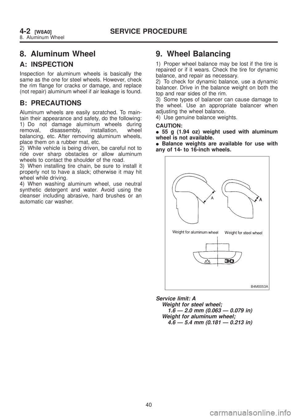
4) Use genuine balance weights.
CAUTION:
I55 g (1.94 oz) weight used with aluminum
wheel is not available.
IBalance weights are available for use with
any of 14- to 16-inch wheels.
B4M0053A
Service limit: A
Weight for steel wheel;
1.6 Ð 2.0 mm (0.063 Ð 0.079 in)
Weight for aluminum wheel;
4.6 Ð 5.4 mm (0.181 Ð 0.213 in)
40
4-2[W8A0]SERVICE PROCEDURE
8. Aluminum Wheel
Page 790 of 1456
10. Installation of Wheel
Assembly to Vehicle
1) Attach the wheel to the hub by aligning the
wheel bolt hole with the hub bolt.
2) Temporarily attach the wheel nuts to the hub
bolts. (In the case of aluminum wheel, use
SUBARU genuine wheel nut for aluminum wheel.)
3) Manually tighten the nuts making sure the
wheel hub hole is aligned correctly to the guide
portion of hub.
4) Tighten the wheel nuts in a diagonal selection
to the specified torque. Use a wheel nut wrench.
Wheel nut tightening torque:
88
±10 N´m (9±1 kg-m, 65±7 ft-lb)
CAUTION:
ITighten the wheel nuts in two or three steps
by gradually increasing the torque and working
diagonally, until the specified torque is
reached. For drum brake models, excess tight-
ening of wheel nuts may cause wheels to ªjud-
derº.
IDo not depress the wrench with a foot;
Always use both hands when tightening.
IMake sure the bolt, nut and the nut seating
surface of the wheel are free from oils.
5) If a wheel is removed for replacement or for
repair of a puncture, retighten the wheel nuts to the
specified torque after running 1,000 km (600
miles).
11. Tire Rotation
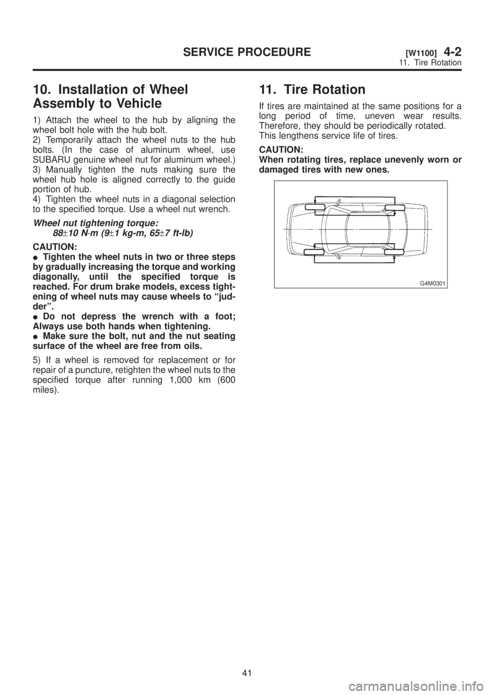
If tires are maintained at the same positions for a
long period of time, uneven wear results.
Therefore, they should be periodically rotated.
This lengthens service life of tires.
CAUTION:
When rotating tires, replace unevenly worn or
damaged tires with new ones.
G4M0301
41
[W1100]4-2SERVICE PROCEDURE
11. Tire Rotation
Page 791 of 1456
10. Installation of Wheel
Assembly to Vehicle
1) Attach the wheel to the hub by aligning the
wheel bolt hole with the hub bolt.
2) Temporarily attach the wheel nuts to the hub
bolts. (In the case of aluminum wheel, use
SUBARU genuine wheel nut for aluminum wheel.)
3) Manually tighten the nuts making sure the
wheel hub hole is aligned correctly to the guide
portion of hub.
4) Tighten the wheel nuts in a diagonal selection
to the specified torque. Use a wheel nut wrench.
Wheel nut tightening torque:
88
±10 N´m (9±1 kg-m, 65±7 ft-lb)
CAUTION:
ITighten the wheel nuts in two or three steps
by gradually increasing the torque and working
diagonally, until the specified torque is
reached. For drum brake models, excess tight-
ening of wheel nuts may cause wheels to ªjud-
derº.
IDo not depress the wrench with a foot;
Always use both hands when tightening.
IMake sure the bolt, nut and the nut seating
surface of the wheel are free from oils.
5) If a wheel is removed for replacement or for
repair of a puncture, retighten the wheel nuts to the
specified torque after running 1,000 km (600
miles).
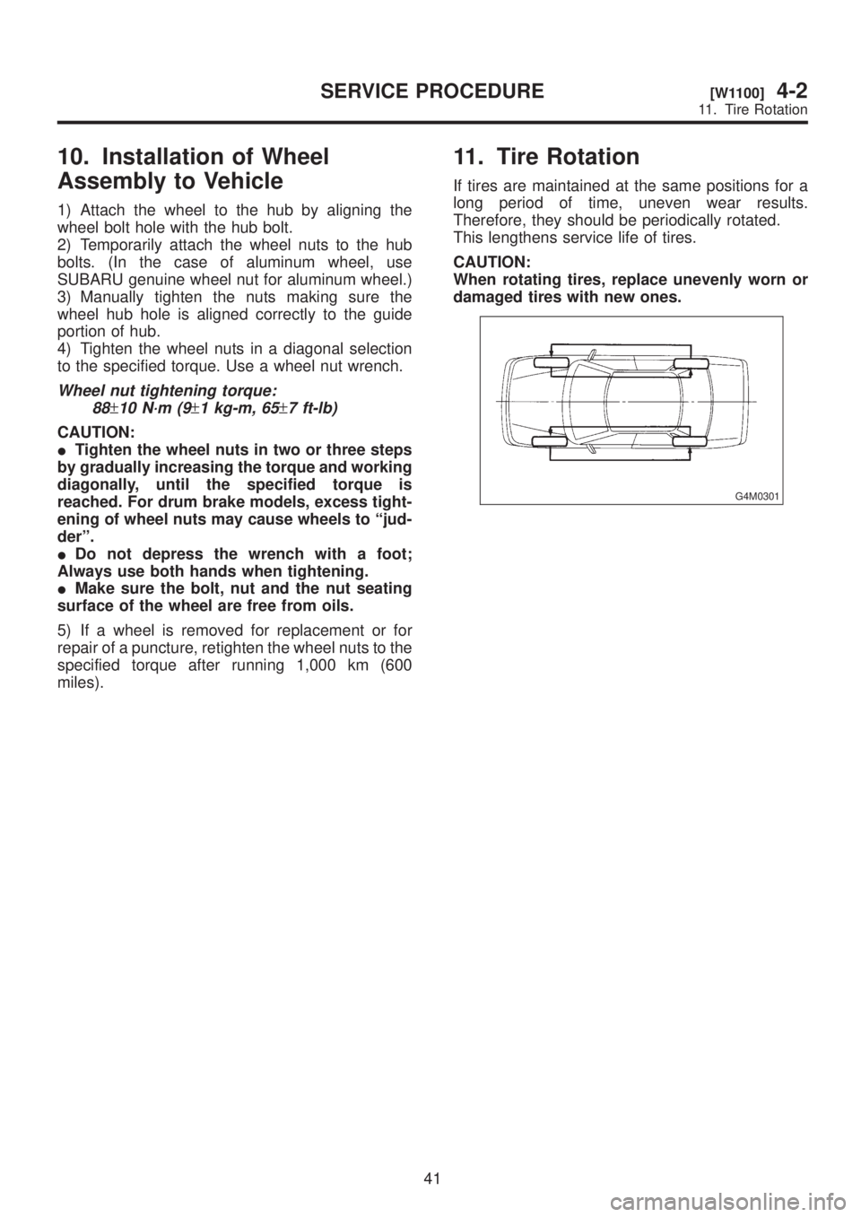
11. Tire Rotation
If tires are maintained at the same positions for a
long period of time, uneven wear results.
Therefore, they should be periodically rotated.
This lengthens service life of tires.
CAUTION:
When rotating tires, replace unevenly worn or
damaged tires with new ones.
G4M0301
41
[W1100]4-2SERVICE PROCEDURE
11. Tire Rotation
Page 793 of 1456
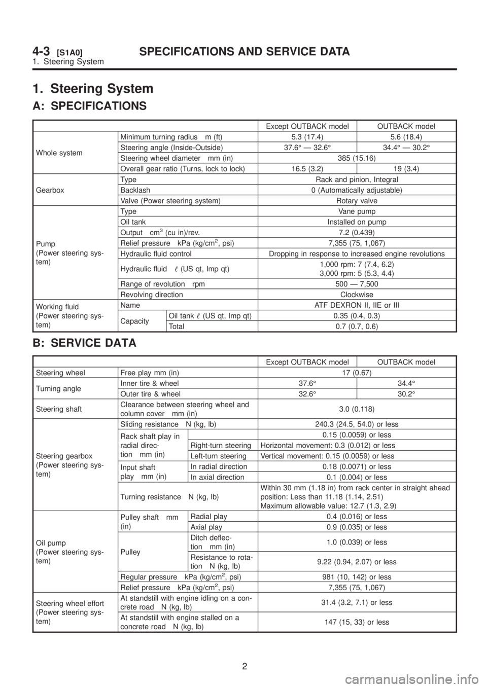
1. Steering System
A: SPECIFICATIONS
Except OUTBACK model OUTBACK model
Whole systemMinimum turning radius m (ft) 5.3 (17.4) 5.6 (18.4)
Steering angle (Inside-Outside) 37.6É Ð 32.6É 34.4É Ð 30.2É
Steering wheel diameter mm (in) 385 (15.16)
Overall gear ratio (Turns, lock to lock) 16.5 (3.2) 19 (3.4)
GearboxType Rack and pinion, Integral
Backlash 0 (Automatically adjustable)
Valve (Power steering system) Rotary valve
Pump
(Power steering sys-
tem)Type Vane pump
Oil tank Installed on pump
Output cm
3(cu in)/rev. 7.2 (0.439)
Relief pressure kPa (kg/cm2, psi) 7,355 (75, 1,067)
Hydraulic fluid control Dropping in response to increased engine revolutions
Hydraulic fluid(US qt, Imp qt)1,000 rpm: 7 (7.4, 6.2)
3,000 rpm: 5 (5.3, 4.4)
Range of revolution rpm 500 Ð 7,500
Revolving direction Clockwise
Working fluid
(Power steering sys-
tem)Name ATF DEXRON II, IIE or III
CapacityOil tank(US qt, Imp qt) 0.35 (0.4, 0.3)
Total 0.7 (0.7, 0.6)
B: SERVICE DATA
Except OUTBACK model OUTBACK model
Steering wheel Free play mm (in) 17 (0.67)
Turning angleInner tire & wheel 37.6É 34.4É
Outer tire & wheel 32.6É 30.2É
Steering shaftClearance between steering wheel and
column cover mm (in)3.0 (0.118)
Steering gearbox
(Power steering sys-
tem)Sliding resistance N (kg, lb) 240.3 (24.5, 54.0) or less
Rack shaft play in
radial direc-
tion mm (in)0.15 (0.0059) or less
Right-turn steering Horizontal movement: 0.3 (0.012) or less
Left-turn steering Vertical movement: 0.15 (0.0059) or less
Input shaft
play mm (in)In radial direction 0.18 (0.0071) or less
In axial direction 0.1 (0.004) or less
Turning resistance N (kg, lb)Within 30 mm (1.18 in) from rack center in straight ahead
position: Less than 11.18 (1.14, 2.51)
Maximum allowable value: 12.7 (1.3, 2.9)
Oil pump
(Power steering sys-
tem)Pulley shaft mm
(in)Radial play 0.4 (0.016) or less
Axial play 0.9 (0.035) or less
PulleyDitch deflec-
tion mm (in)1.0 (0.039) or less
Resistance to rota-
tion N (kg, lb)9.22 (0.94, 2.07) or less
Regular pressure kPa (kg/cm
2, psi) 981 (10, 142) or less
Relief pressure kPa (kg/cm2, psi) 7,355 (75, 1,067)
Steering wheel effort
(Power steering sys-
tem)At standstill with engine idling on a con-
crete road N (kg, lb)31.4 (3.2, 7.1) or less
At standstill with engine stalled on a
concrete road N (kg, lb)147 (15, 33) or less
2
4-3[S1A0]SPECIFICATIONS AND SERVICE DATA
1. Steering System