SUBARU LEGACY 1999 Service Repair Manual
LEGACY 1999
SUBARU
SUBARU
https://www.carmanualsonline.info/img/17/57435/w960_57435-0.png
SUBARU LEGACY 1999 Service Repair Manual
Trending: air condition, oil viscosity, wiring diagram, window, diff, turn signal bulb, sunroof
Page 351 of 1456
2. 2500 cc MODEL
1) Disconnect battery ground cable.
G6M0095
2) Remove front pillar lower trim.
B2M0672A
3) Detach floor mat of front passenger seat.
B2M0673A
4) Remove protect cover.
B2M0674
5) Remove vinyl cover and nuts which hold ECM
to bracket.
B2M0675A
6) Remove clip from bracket.
B2M0676A
7) Remove connector cover.
B2M0677A
8) Disconnect ECM connector.
B2M0678
86
2-7[W15A2]SERVICE PROCEDURE
15. Engine Control Module
Page 352 of 1456
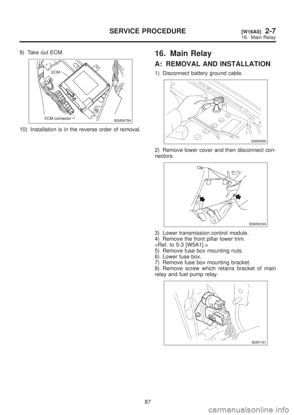
9) Take out ECM.
B2M0679A
10) Installation is in the reverse order of removal.
16. Main Relay
A: REMOVAL AND INSTALLATION
1) Disconnect battery ground cable.
G6M0095
2) Remove lower cover and then disconnect con-
nectors.
B5M0024A
3) Lower transmission control module.
4) Remove the front pillar lower trim.
5) Remove fuse box mounting nuts.
6) Lower fuse box.
7) Remove fuse box mounting bracket.
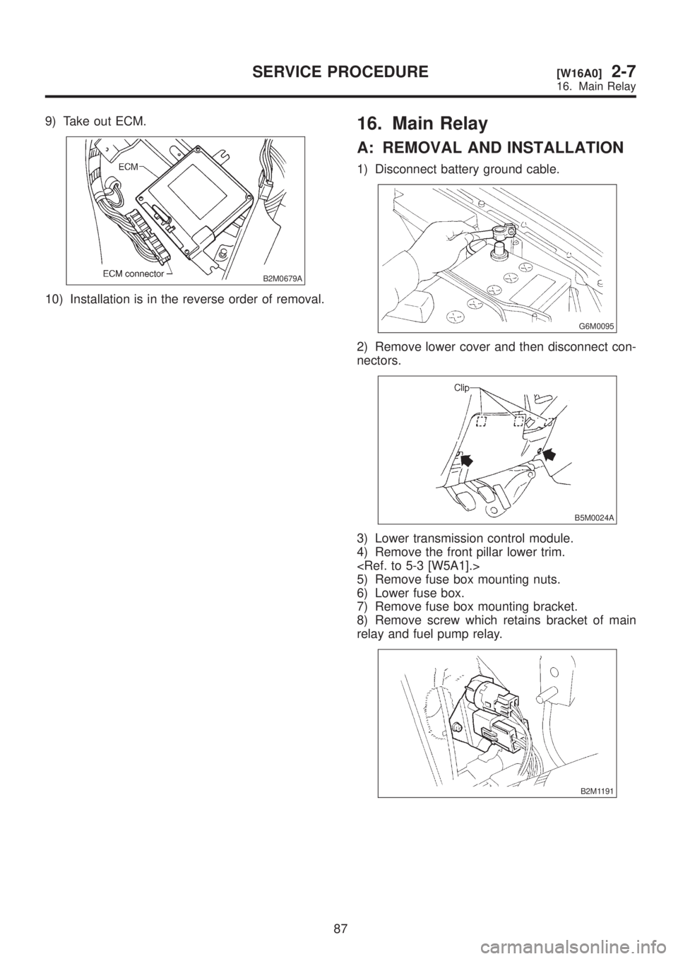
8) Remove screw which retains bracket of main
relay and fuel pump relay.
B2M1191
87
[W16A0]2-7SERVICE PROCEDURE
16. Main Relay
Page 353 of 1456
9) Take out ECM.
B2M0679A
10) Installation is in the reverse order of removal.
16. Main Relay
A: REMOVAL AND INSTALLATION
1) Disconnect battery ground cable.
G6M0095
2) Remove lower cover and then disconnect con-
nectors.
B5M0024A
3) Lower transmission control module.
4) Remove the front pillar lower trim.
5) Remove fuse box mounting nuts.
6) Lower fuse box.
7) Remove fuse box mounting bracket.
8) Remove screw which retains bracket of main
relay and fuel pump relay.
B2M1191
87
[W16A0]2-7SERVICE PROCEDURE
16. Main Relay
Page 354 of 1456
17. Fuel Pump Relay
A: REMOVAL AND INSTALLATION
1) Disconnect battery ground cable.
G6M0095
2) Remove lower cover and then disconnect con-
nectors.
B5M0024A
3) Lower transmission control module.
4) Remove the front pillar lower trim.
5) Remove fuse box mounting nuts.
6) Lower fuse box.
7) Remove fuse box mounting bracket.
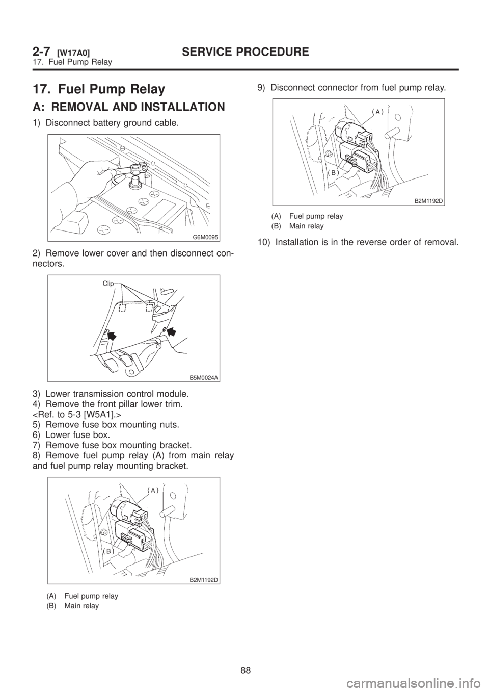
8) Remove fuel pump relay (A) from main relay
and fuel pump relay mounting bracket.
B2M1192D
(A) Fuel pump relay
(B) Main relay
9) Disconnect connector from fuel pump relay.
B2M1192D
(A) Fuel pump relay
(B) Main relay
10) Installation is in the reverse order of removal.
88
2-7[W17A0]SERVICE PROCEDURE
17. Fuel Pump Relay
Page 355 of 1456
18. Air Intake Chamber (Except
2200 cc California Spec.
Vehicles)
A: REMOVAL AND INSTALLATION
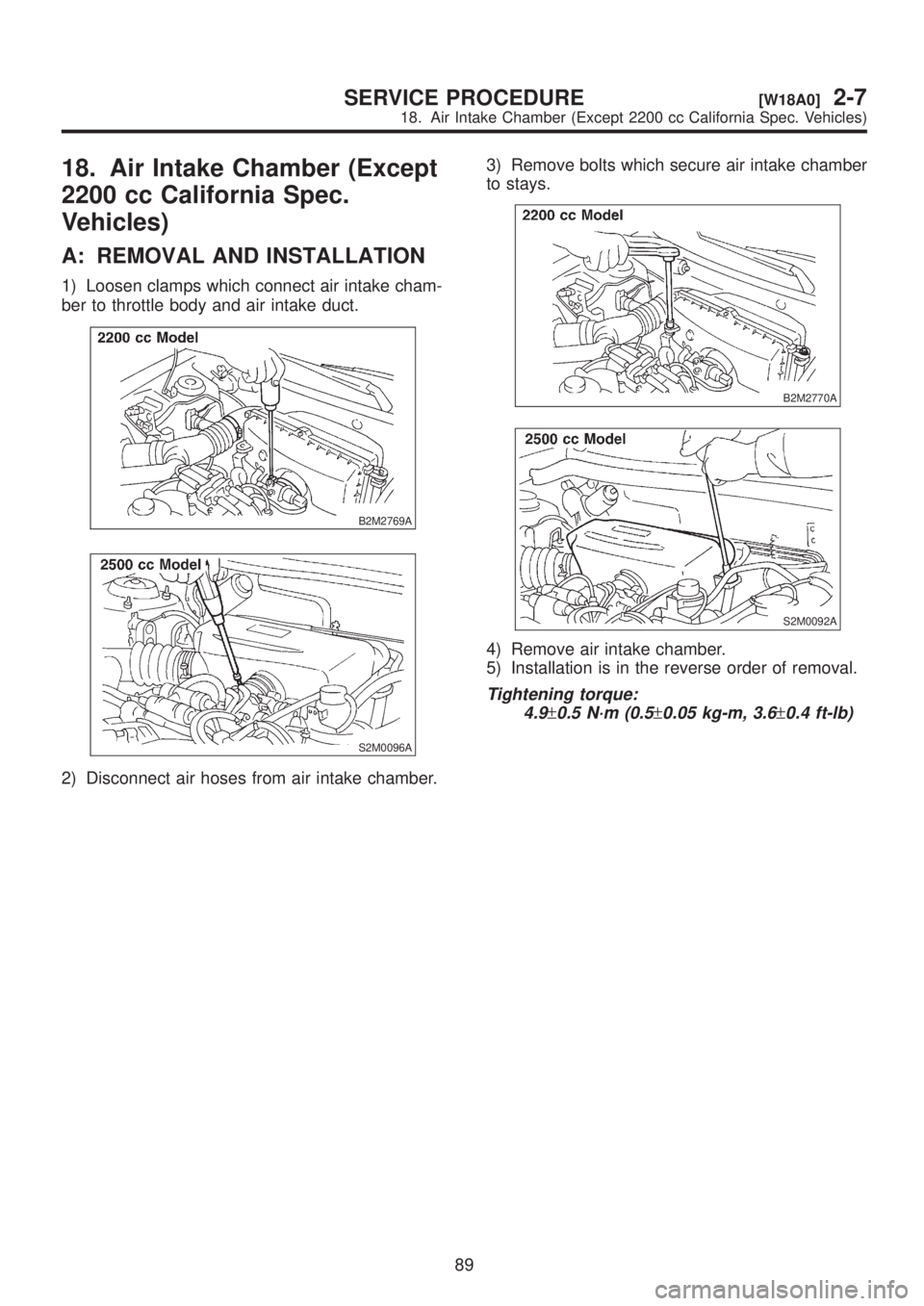
1) Loosen clamps which connect air intake cham-
ber to throttle body and air intake duct.
B2M2769A
S2M0096A
2) Disconnect air hoses from air intake chamber.3) Remove bolts which secure air intake chamber
to stays.
B2M2770A
S2M0092A
4) Remove air intake chamber.
5) Installation is in the reverse order of removal.
Tightening torque:
4.9
±0.5 N´m (0.5±0.05 kg-m, 3.6±0.4 ft-lb)
89
[W18A0]2-7SERVICE PROCEDURE
18. Air Intake Chamber (Except 2200 cc California Spec. Vehicles)
Page 356 of 1456
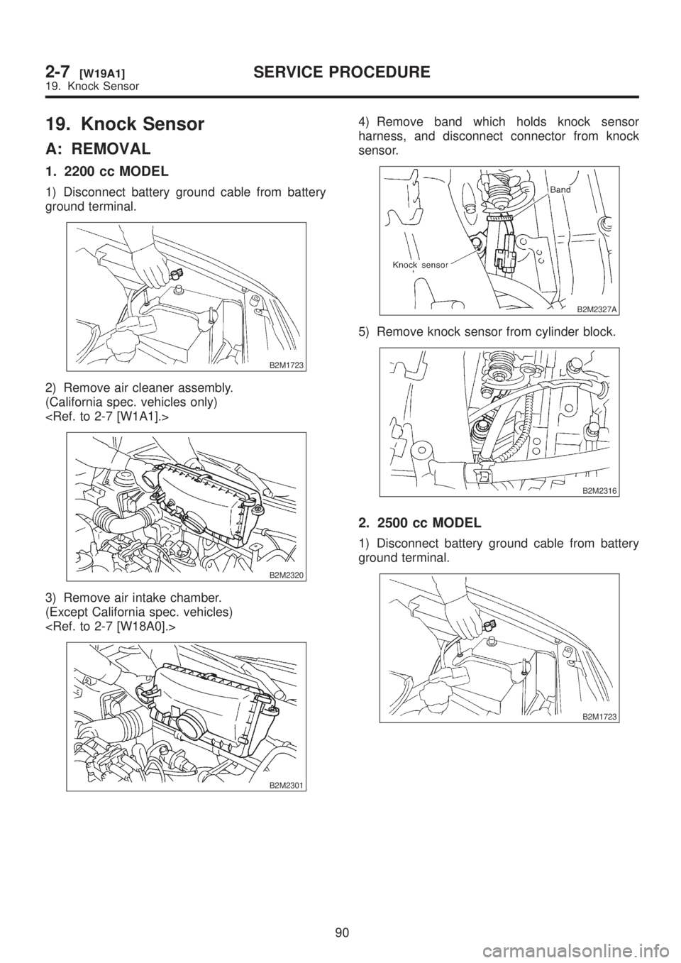
19. Knock Sensor
A: REMOVAL
1. 2200 cc MODEL
1) Disconnect battery ground cable from battery
ground terminal.
B2M1723
2) Remove air cleaner assembly.
(California spec. vehicles only)
B2M2320
3) Remove air intake chamber.
(Except California spec. vehicles)
B2M2301
4) Remove band which holds knock sensor
harness, and disconnect connector from knock
sensor.
B2M2327A
5) Remove knock sensor from cylinder block.
B2M2316
2. 2500 cc MODEL
1) Disconnect battery ground cable from battery
ground terminal.
B2M1723
90
2-7[W19A1]SERVICE PROCEDURE
19. Knock Sensor
Page 357 of 1456
2) Remove air intake chamber.
B2M1683
3) Remove operating cylinder. (MT vehicles only)
B2M1179D
NOTE:
Place the operating cylinder where it will not inter-
fere the work in process.
B2M1684
4) Disconnect knock sensor connector.
B2M1686
5) Remove knock sensor from cylinder block.
B2M1682
B: INSTALLATION
1. 2200 cc MODEL
1) Install knock sensor to cylinder block.
NOTE:
The knock sensor cord which is extracted from the
sensor must be positioned at a 45É angle against
the rear side of the engine.
Tightening torque:
23.5
±2.9 N´m (2.4±0.3 kg-m, 17.3±2.1 ft-lb)
B2M2316
2) Connect knock sensor connector and hold
knock sensor harness with band.
3) Install air intake chamber. (Except California
spec. vehicles)
B2M2301
91
[W19B1]2-7SERVICE PROCEDURE
19. Knock Sensor
Page 358 of 1456
4) Install air cleaner assembly. (California spec.
vehicles only)
B2M2320
5) Connect battery ground cable to battery ground
terminal.
B2M1723
2. 2500 cc MODEL
1) Install knock sensor to cylinder block.
NOTE:
The knock sensor cord which is extracted from the
sensor must be positioned at a 45É angle against
the rear side of the engine.
Tightening torque:
23.5
±2.9 N´m (2.4±0.3 kg-m, 17.3±2.1 ft-lb)
B2M1682A
2) Connect knock sensor connector.
B2M1686
NOTE:
The knock sensor connector must be connected
behind the engine coolant hose within the engine
components.
B2M1688A
B2M1689A
92
2-7[W19B2]SERVICE PROCEDURE
19. Knock Sensor
Page 359 of 1456
3) Install operating cylinder. (MT vehicles only)
NOTE:
Apply grease to contact point of release lever and
operating cylinder rod.
Tightening torque:
37
±3 N´m (3.8±0.3 kg-m, 27.3±2.2 ft-lb)
B2M1179E
4) Install air intake chamber.
[W18A0].>
B2M1683
5) Connect battery ground cable to battery ground
terminal.
B2M1723
20. Intake Manifold Pressure
Sensor (2200 cc California
Spec. Vehicles only)
A: REMOVAL AND INSTALLATION
1) Disconnect battery ground cable.
B2M1723
2) Remove idle air control solenoid valve.
2-7 [W12A1].>
B2M2364
3) Disconnect connector from intake manifold
pressure sensor.
B2M2372
93
[W20A0]2-7SERVICE PROCEDURE
20. Intake Manifold Pressure Sensor (2200 cc California Spec. Vehicles only)
Page 360 of 1456
3) Install operating cylinder. (MT vehicles only)
NOTE:
Apply grease to contact point of release lever and
operating cylinder rod.
Tightening torque:
37
±3 N´m (3.8±0.3 kg-m, 27.3±2.2 ft-lb)
B2M1179E
4) Install air intake chamber.
[W18A0].>
B2M1683
5) Connect battery ground cable to battery ground
terminal.
B2M1723
20. Intake Manifold Pressure
Sensor (2200 cc California
Spec. Vehicles only)
A: REMOVAL AND INSTALLATION
1) Disconnect battery ground cable.
B2M1723
2) Remove idle air control solenoid valve.
2-7 [W12A1].>
B2M2364
3) Disconnect connector from intake manifold
pressure sensor.
B2M2372
93
[W20A0]2-7SERVICE PROCEDURE
20. Intake Manifold Pressure Sensor (2200 cc California Spec. Vehicles only)
Trending: Fuel drain valve, fuse box location, oil type, alarm, fuel injector, stop start, set clock
![SUBARU LEGACY 1999 Service Repair Manual 2. 2500 cc MODEL
1) Disconnect battery ground cable.
G6M0095
2) Remove front pillar lower trim.
<Ref. to 5-3 [W5A1].>
B2M0672A
3) Detach floor mat of front passenger seat.
B2M0673A
4) Remove protect c SUBARU LEGACY 1999 Service Repair Manual 2. 2500 cc MODEL
1) Disconnect battery ground cable.
G6M0095
2) Remove front pillar lower trim.
<Ref. to 5-3 [W5A1].>
B2M0672A
3) Detach floor mat of front passenger seat.
B2M0673A
4) Remove protect c](/img/17/57435/w960_57435-350.png)
![SUBARU LEGACY 1999 Service Repair Manual 2) Remove air intake chamber.
<Ref. to 2-7 [W18A0].>
B2M1683
3) Remove operating cylinder. (MT vehicles only)
<Ref. to 2-10 [W5A0].>
B2M1179D
NOTE:
Place the operating cylinder where it will not inter SUBARU LEGACY 1999 Service Repair Manual 2) Remove air intake chamber.
<Ref. to 2-7 [W18A0].>
B2M1683
3) Remove operating cylinder. (MT vehicles only)
<Ref. to 2-10 [W5A0].>
B2M1179D
NOTE:
Place the operating cylinder where it will not inter](/img/17/57435/w960_57435-356.png)
![SUBARU LEGACY 1999 Service Repair Manual 4) Install air cleaner assembly. (California spec.
vehicles only) <Ref. to 2-7 [W1A1].>
B2M2320
5) Connect battery ground cable to battery ground
terminal.
B2M1723
2. 2500 cc MODEL
1) Install knock se SUBARU LEGACY 1999 Service Repair Manual 4) Install air cleaner assembly. (California spec.
vehicles only) <Ref. to 2-7 [W1A1].>
B2M2320
5) Connect battery ground cable to battery ground
terminal.
B2M1723
2. 2500 cc MODEL
1) Install knock se](/img/17/57435/w960_57435-357.png)
![SUBARU LEGACY 1999 Service Repair Manual 3) Install operating cylinder. (MT vehicles only)
NOTE:
Apply grease to contact point of release lever and
operating cylinder rod. <Ref. to 2-10 [W5A0].>
Tightening torque:
37
±3 N´m (3.8±0.3 kg-m, SUBARU LEGACY 1999 Service Repair Manual 3) Install operating cylinder. (MT vehicles only)
NOTE:
Apply grease to contact point of release lever and
operating cylinder rod. <Ref. to 2-10 [W5A0].>
Tightening torque:
37
±3 N´m (3.8±0.3 kg-m,](/img/17/57435/w960_57435-358.png)
![SUBARU LEGACY 1999 Service Repair Manual 3) Install operating cylinder. (MT vehicles only)
NOTE:
Apply grease to contact point of release lever and
operating cylinder rod. <Ref. to 2-10 [W5A0].>
Tightening torque:
37
±3 N´m (3.8±0.3 kg-m, SUBARU LEGACY 1999 Service Repair Manual 3) Install operating cylinder. (MT vehicles only)
NOTE:
Apply grease to contact point of release lever and
operating cylinder rod. <Ref. to 2-10 [W5A0].>
Tightening torque:
37
±3 N´m (3.8±0.3 kg-m,](/img/17/57435/w960_57435-359.png)