Duct SUBARU TRIBECA 2009 1.G Service Workshop Manual
[x] Cancel search | Manufacturer: SUBARU, Model Year: 2009, Model line: TRIBECA, Model: SUBARU TRIBECA 2009 1.GPages: 2453, PDF Size: 46.32 MB
Page 188 of 2453
ET-2
General Description
ENTERTAINMENT
1. General Description
A: CAUTION
•Before disassembling or reassembling parts, al-
ways disconnect the battery ground cable from bat-
tery.
•When replacing the audio, control module and
other parts provided with memory functions, record
the memory contents before disconnecting the bat-
tery ground cable. Otherwise, the memory is
cleared.
•Reassemble the parts in the reverse order of dis-
assembly procedure unless otherwise indicated.
•Adjust parts to the given specifications.
•Connect the connectors securely during reas-
sembly.
•After reassembly, make sure functional parts op-
erate smoothly.
B: PREPARATION TOOL
1. GENERAL TOOL
TOOL NAME REMARKS
Circuit Tester Used for measuring resis-
tance and voltage.
Conductive silver composition
(DUPONT No. 4817 or equiv-
alent)
Used for repairing antenna
wire.
Page 204 of 2453
ET-19
Antenna
ENTERTAINMENT
14.Antenna
A: INSPECTION
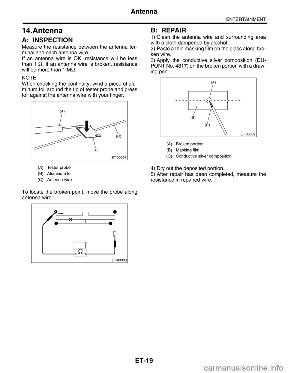
Measure the resistance between the antenna ter-
minal and each antenna wire.
If an antenna wire is OK, resistance will be less
than 1 Ω. If an antenna wire is broken, resistance
will be more than 1 MΩ.
NOTE:
When checking the continuity, wind a piece of alu-
minum foil around the tip of tester probe and press
foil against the antenna wire with your finger.
To locate the broken point, move the probe along
antenna wire.
B: REPAIR
1) Clean the antenna wire and surrounding area
with a cloth dampened by alcohol.
2) Paste a thin masking film on the glass along bro-
ken wire.
3) Apply the conductive silver composition (DU-
PONT No. 4817) on the broken portion with a draw-
ing pen.
4) Dry out the deposited portion.
5) After repair has been completed, measure the
resistance in repaired wire.
(A) Tester probe
(B) Aluminum foil
(C) Antenna wire
ET-00007
(B)
(C)
(A)
ET-00008
(A) Broken portion
(B) Masking film
(C) Conductive silver composition
ET-00009
(B)
(C)
(A)
Page 220 of 2453
ET-16
Tweeter
ENTERTAINMENT
11.Tweeter
A: REMOVAL
1. FRONT
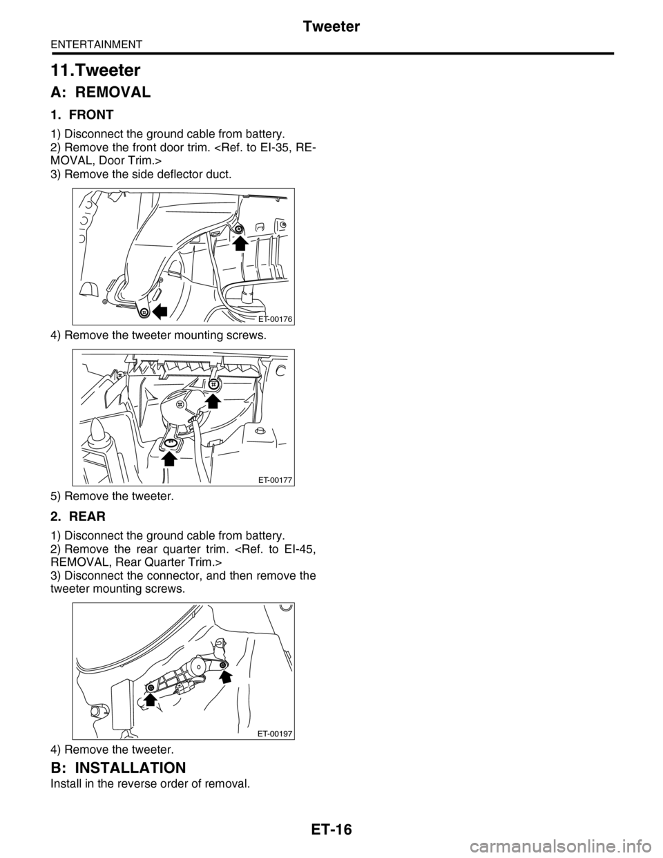
1) Disconnect the ground cable from battery.
2) Remove the front door trim.
3) Remove the side deflector duct.
4) Remove the tweeter mounting screws.
5) Remove the tweeter.
2. REAR
1) Disconnect the ground cable from battery.
2) Remove the rear quarter trim.
3) Disconnect the connector, and then remove the
tweeter mounting screws.
4) Remove the tweeter.
B: INSTALLATION
Install in the reverse order of removal.
ET-00176
ET-00177
Page 241 of 2453
EB-22
Rear Gate
EXTERIOR BODY PANELS
8. Rear Gate
A: REMOVAL
1. REAR GATE PANEL
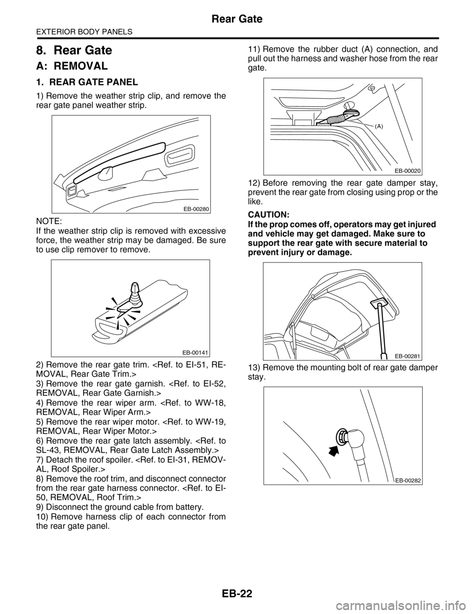
1) Remove the weather strip clip, and remove the
rear gate panel weather strip.
NOTE:
If the weather strip clip is removed with excessive
force, the weather strip may be damaged. Be sure
to use clip remover to remove.
2) Remove the rear gate trim.
3) Remove the rear gate garnish.
4) Remove the rear wiper arm.
5) Remove the rear wiper motor.
6) Remove the rear gate latch assembly.
7) Detach the roof spoiler.
8) Remove the roof trim, and disconnect connector
from the rear gate harness connector.
9) Disconnect the ground cable from battery.
10) Remove harness clip of each connector from
the rear gate panel.
11) Remove the rubber duct (A) connection, and
pull out the harness and washer hose from the rear
gate.
12) Before removing the rear gate damper stay,
prevent the rear gate from closing using prop or the
like.
CAUTION:
If the prop comes off, operators may get injured
and vehicle may get damaged. Make sure to
support the rear gate with secure material to
prevent injury or damage.
13) Remove the mounting bolt of rear gate damper
stay.
EB-00280
EB-00141
(A)
EB-00020
EB-00281
EB-00282
Page 254 of 2453
EI-12
General Description
EXTERIOR/INTERIOR TRIM
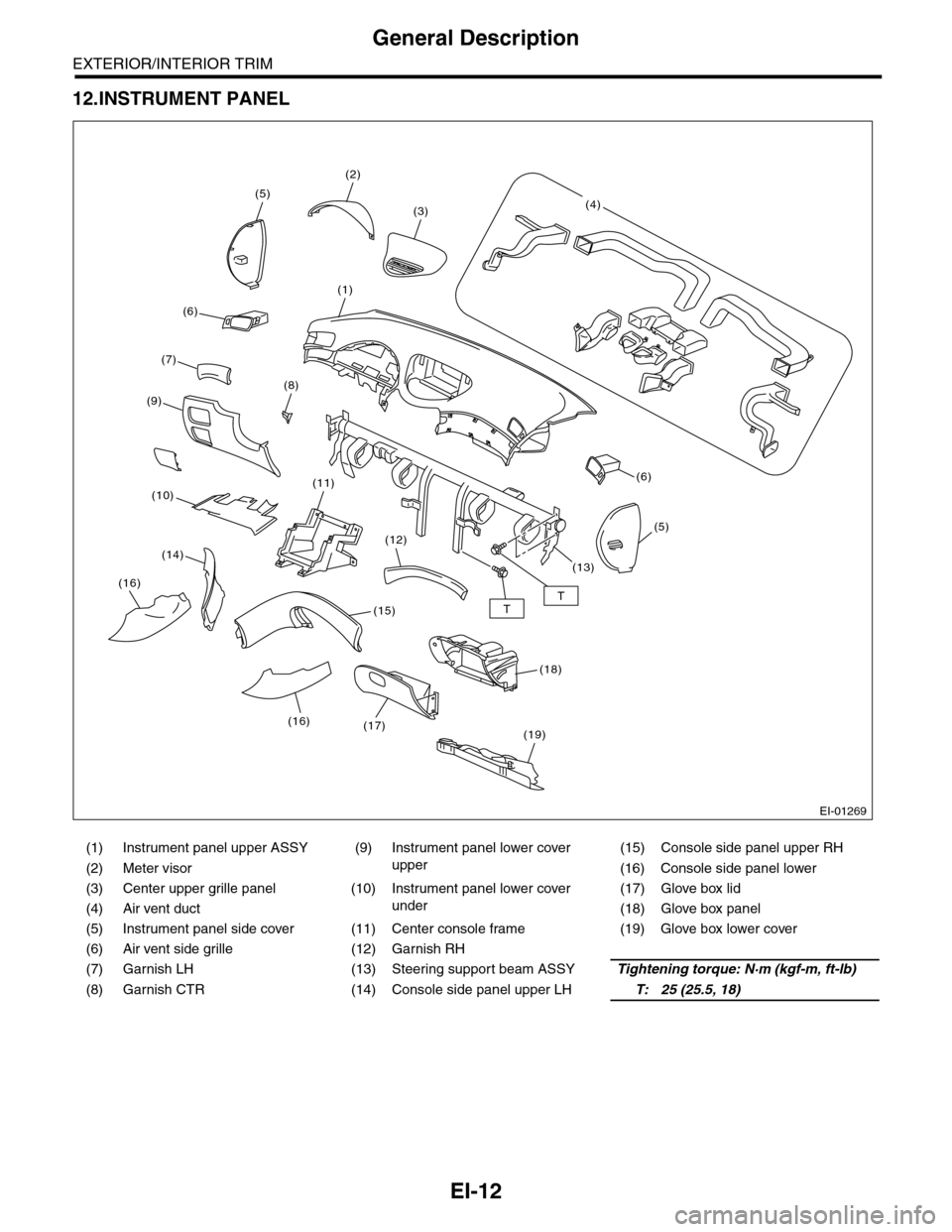
12.INSTRUMENT PANEL
(1) Instrument panel upper ASSY (9)
Instrument panel lower cover
upper
(15) Console side panel upper RH
(2) Meter visor (16) Console side panel lower
(3) Center upper grille panel (10)
Instrument panel lower cover
under
(17) Glove box lid
(4) Air vent duct (18) Glove box panel
(5) Instrument panel side cover (11) Center console frame (19) Glove box lower cover
(6) Air vent side grille (12) Garnish RH
(7) Garnish LH (13) Steering support beam ASSYTightening torque: N·m (kgf-m, ft-lb)
(8) Garnish CTR (14) Console side panel upper LHT: 25 (25.5, 18)
EI-01269
TT
(2)
(5)
(1)
(8)
(6)
(19)
(11)
(12)
(15)
(17)
(5)
(6)
(3)(4)
(7)
(9)
(10)
(14)
(16)
(18)
(13)
(16)
Page 283 of 2453
EI-41
Instrument Panel Assembly
EXTERIOR/INTERIOR TRIM
13) Make sure that the instrument panel upper is
removed from the steering support beam
14) Disconnect the connectors, and remove the in-
strument panel from vehicle body.
15) Remove the heater vent duct.
16) Remove the air vent grille.
17) Remove the passenger airbag module.
ule.>
2. STEERING SUPPORT BEAM
1) Remove the instrument panel upper.
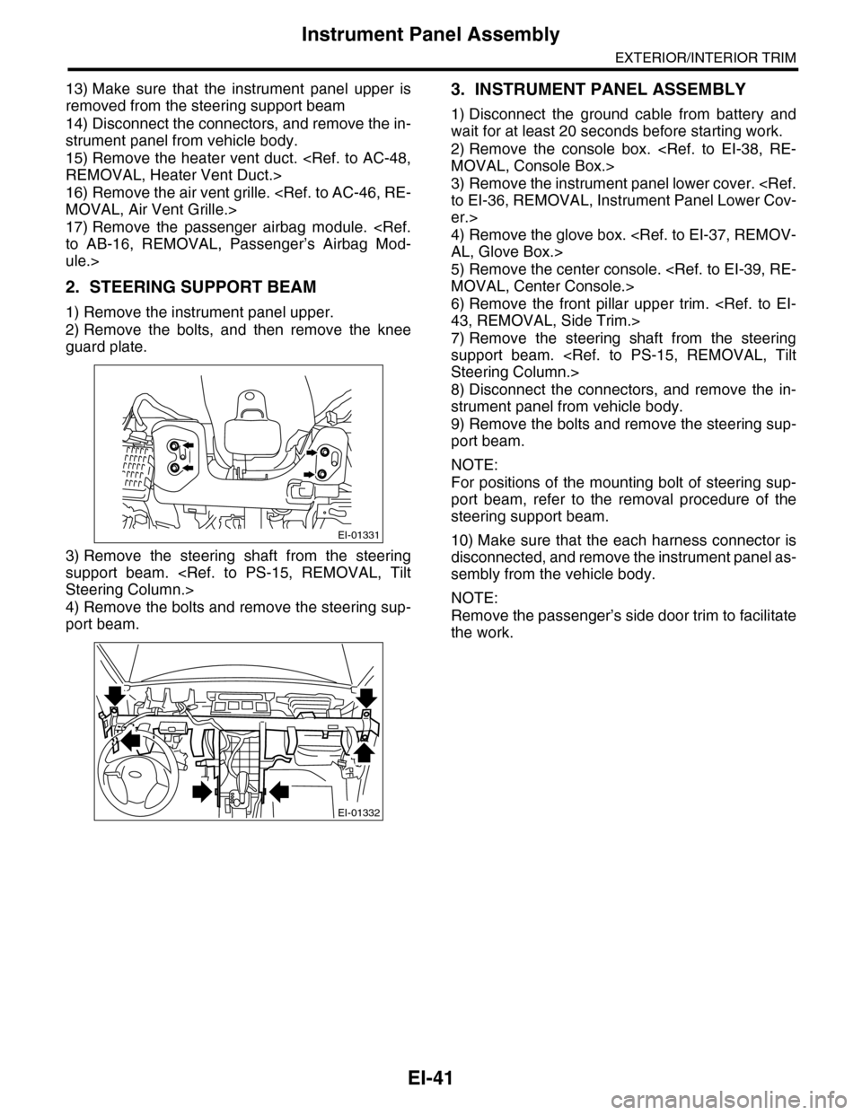
2) Remove the bolts, and then remove the knee
guard plate.
3) Remove the steering shaft from the steering
support beam.
4) Remove the bolts and remove the steering sup-
port beam.
3. INSTRUMENT PANEL ASSEMBLY
1) Disconnect the ground cable from battery and
wait for at least 20 seconds before starting work.
2) Remove the console box.
3) Remove the instrument panel lower cover.
er.>
4) Remove the glove box.
5) Remove the center console.
6) Remove the front pillar upper trim.
7) Remove the steering shaft from the steering
support beam.
8) Disconnect the connectors, and remove the in-
strument panel from vehicle body.
9) Remove the bolts and remove the steering sup-
port beam.
NOTE:
For positions of the mounting bolt of steering sup-
port beam, refer to the removal procedure of the
steering support beam.
10) Make sure that the each harness connector is
disconnected, and remove the instrument panel as-
sembly from the vehicle body.
NOTE:
Remove the passenger’s side door trim to facilitate
the work.
EI-01331
EI-01332
Page 300 of 2453
GW-5
General Description
GLASS/WINDOWS/MIRRORS
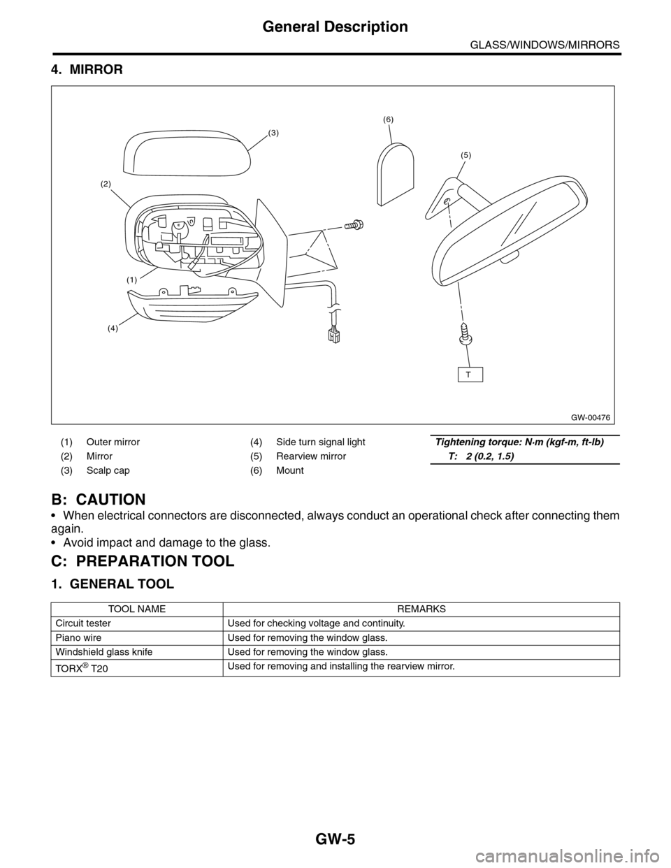
4. MIRROR
B: CAUTION
•When electrical connectors are disconnected, always conduct an operational check after connecting them
again.
•Avoid impact and damage to the glass.
C: PREPARATION TOOL
1. GENERAL TOOL
(1) Outer mirror (4) Side turn signal lightTightening torque: N·m (kgf-m, ft-lb)
(2) Mirror (5) Rearview mirrorT: 2 (0.2, 1.5)
(3) Scalp cap (6) Mount
TOOL NAME REMARKS
Circuit tester Used for checking voltage and continuity.
Piano wire Used for removing the window glass.
Windshield glass knife Used for removing the window glass.
TO RX® T20Used for removing and installing the rearview mirror.
GW-00476
(5)
(6)
(2)
(3)
(4)
(1)
T
Page 318 of 2453
GW-23
Rear Gate Glass
GLASS/WINDOWS/MIRRORS
6) About one hour after installation, conduct a leak test.
7) After completion of all work, allow the vehicle to
stand for about 24 hours.
NOTE:
•When door is opened/closed after glass is bond-
ed, always lower the door glass first, and then
open/close it carefully.
•Move the vehicle slowly.
•For minimum drying time and vehicle standing
time before driving after bonding, follow instruc-
tions or instruction manual from the adhesive man-
ufacturer.
•When a vehicle is returned to the user, tell him or
her that the vehicle should not be subjected to
heavy impact for at least three days.
8) Connect the rear defogger terminals.
9) Install the rear wiper.
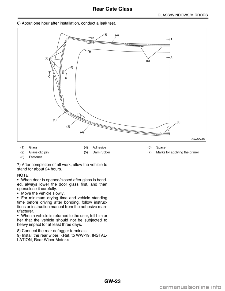
(1) Glass (4) Adhesive (6) Spacer
(2) Glass clip pin (5) Dam rubber (7) Marks for applying the primer
(3) Fastener
Page 321 of 2453
GW-26
Rear Window Defogger
GLASS/WINDOWS/MIRRORS
5) Connect the tester probe of positive lead of volt-
meter to positive terminal of heat wire and move
tester probe of negative lead along the heat wire up
to the negative terminal end. If voltage changes
from zero to several volts during movement of
tester probe, heat wire is open at the voltage
change point.
B: REPAIR
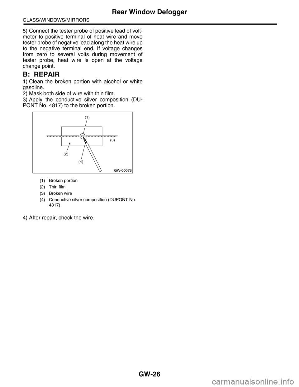
1) Clean the broken portion with alcohol or white
gasoline.
2) Mask both side of wire with thin film.
3) Apply the conductive silver composition (DU-
PONT No. 4817) to the broken portion.
4) After repair, check the wire.
(1) Broken portion
(2) Thin film
(3) Broken wire
(4) Conductive silver composition (DUPONT No.
4817)
GW-00078
(2)
(3)
(4)
(1)
Page 335 of 2453
AC-9
General Description
HVAC SYSTEM (HEATER, VENTILATOR AND A/C)
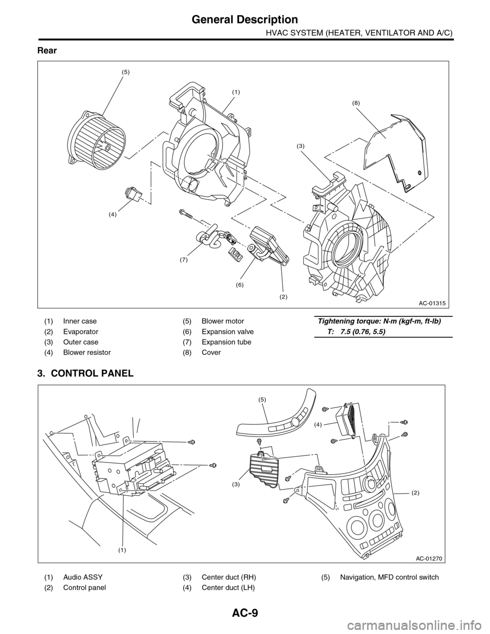
Rear
3. CONTROL PANEL
(1) Inner case (5) Blower motorTightening torque: N·m (kgf-m, ft-lb)
(2) Evaporator (6) Expansion valveT: 7.5 (0.76, 5.5)
(3) Outer case (7) Expansion tube
(4) Blower resistor (8) Cover
(1) Audio ASSY (3) Center duct (RH) (5) Navigation, MFD control switch
(2) Control panel (4) Center duct (LH)
AC-01315
(1)
(2)
(6)
(7)
(3)
(5)
(4)
(8)
AC-01270
(1)
(2)
(3)
(4)
(5)