Duct SUBARU TRIBECA 2009 1.G Service User Guide
[x] Cancel search | Manufacturer: SUBARU, Model Year: 2009, Model line: TRIBECA, Model: SUBARU TRIBECA 2009 1.GPages: 2453, PDF Size: 46.32 MB
Page 339 of 2453
AC-13
General Description
HVAC SYSTEM (HEATER, VENTILATOR AND A/C)
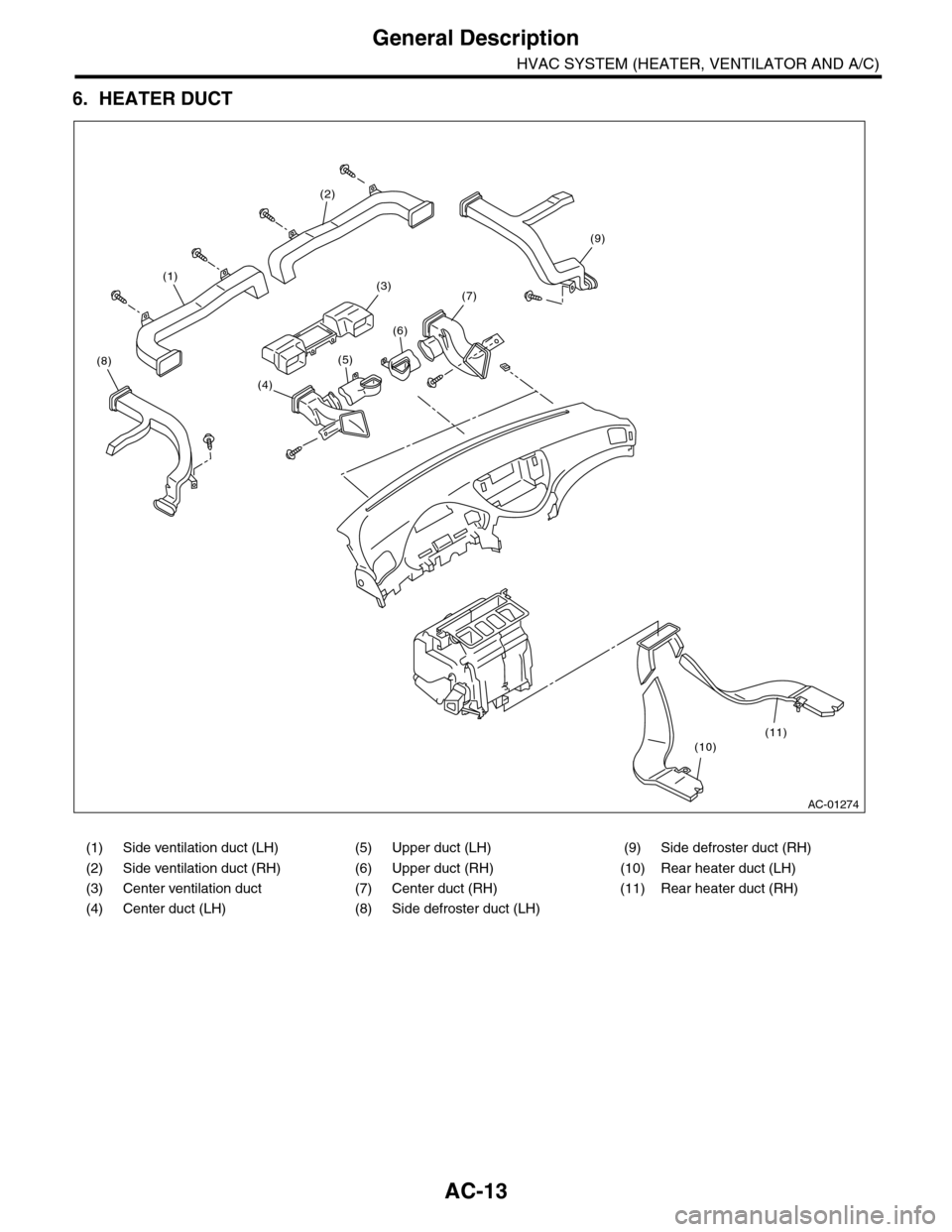
6. HEATER DUCT
(1) Side ventilation duct (LH) (5) Upper duct (LH) (9) Side defroster duct (RH)
(2) Side ventilation duct (RH) (6) Upper duct (RH) (10) Rear heater duct (LH)
(3) Center ventilation duct (7) Center duct (RH) (11) Rear heater duct (RH)
(4) Center duct (LH) (8) Side defroster duct (LH)
AC-01274
(7)
(5)
(6)
(10)(11)
(1)
(2)
(9)
(4)
(3)
(8)
Page 373 of 2453
AC-47
Heater Duct
HVAC SYSTEM (HEATER, VENTILATOR AND A/C)
26.Heater Duct
A: REMOVAL
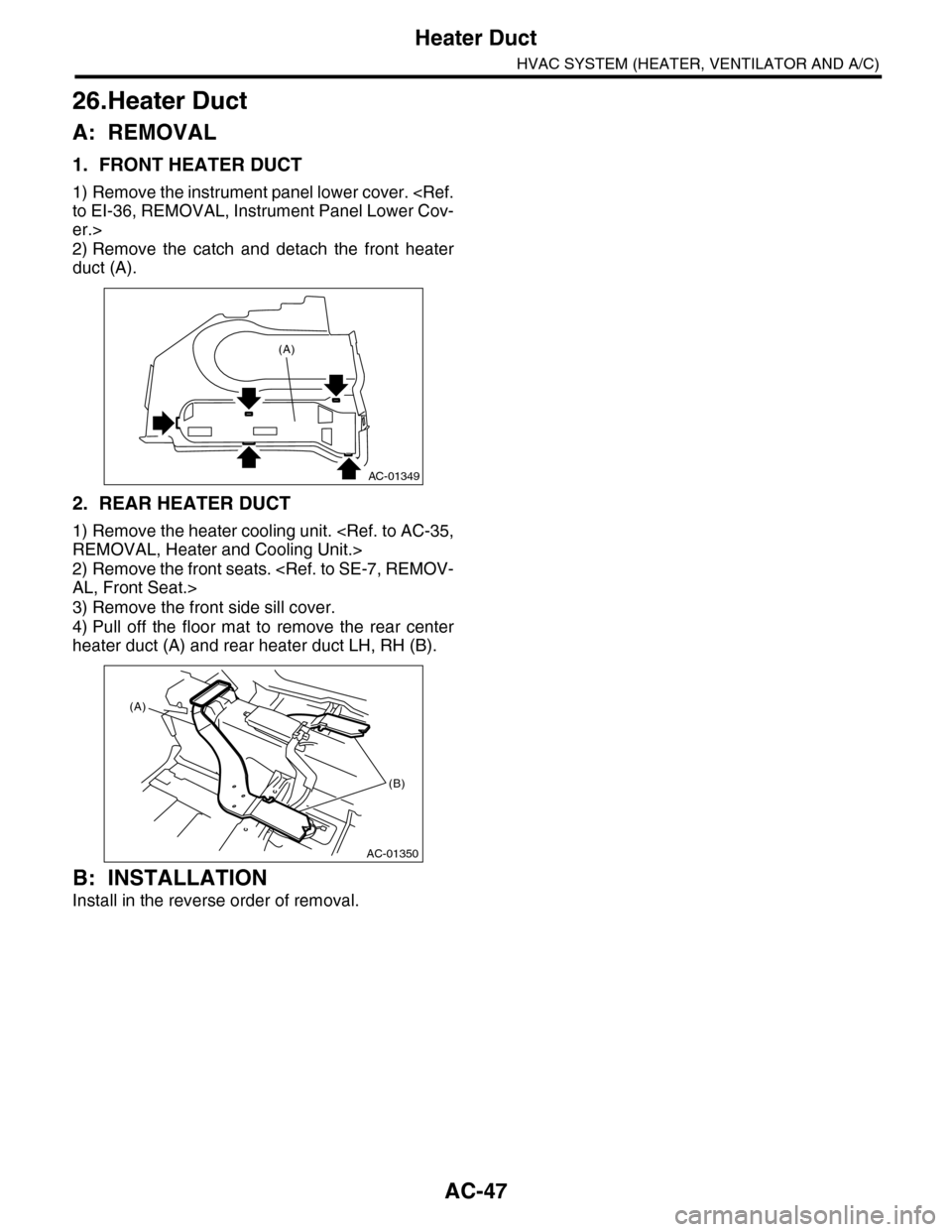
1. FRONT HEATER DUCT
1) Remove the instrument panel lower cover.
er.>
2) Remove the catch and detach the front heater
duct (A).
2. REAR HEATER DUCT
1) Remove the heater cooling unit.
2) Remove the front seats.
3) Remove the front side sill cover.
4) Pull off the floor mat to remove the rear center
heater duct (A) and rear heater duct LH, RH (B).
B: INSTALLATION
Install in the reverse order of removal.
AC-01349
(A)
AC-01350
(A)
(B)
Page 374 of 2453
AC-48
Heater Vent Duct
HVAC SYSTEM (HEATER, VENTILATOR AND A/C)
27.Heater Vent Duct
A: REMOVAL
1. INSTRUMENT
1) Remove the instrument panel.
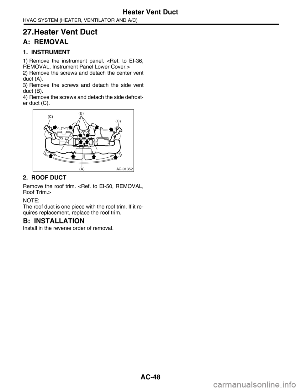
2) Remove the screws and detach the center vent
duct (A).
3) Remove the screws and detach the side vent
duct (B).
4) Remove the screws and detach the side defrost-
er duct (C).
2. ROOF DUCT
Remove the roof trim.
NOTE:
The roof duct is one piece with the roof trim. If it re-
quires replacement, replace the roof trim.
B: INSTALLATION
Install in the reverse order of removal.
AC-01352
(C)(B)
(C)
(A)
Page 376 of 2453
AC-50
General Diagnostic Table
HVAC SYSTEM (HEATER, VENTILATOR AND A/C)
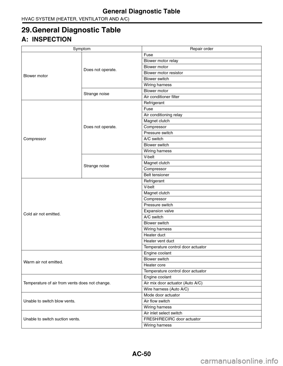
29.General Diagnostic Table
A: INSPECTION
Symptom Repair order
Blower motor
Does not operate.
Fuse
Blower motor relay
Blower motor
Blower motor resistor
Blower switch
Wiring harness
Strange noiseBlower motor
Air conditioner filter
Compressor
Does not operate.
Refrigerant
Fuse
Air conditioning relay
Magnet clutch
Compressor
Pressure switch
A/C switch
Blower switch
Wiring harness
Strange noise
V- b e l t
Magnet clutch
Compressor
Belt tensioner
Cold air not emitted.
Refrigerant
V- b e l t
Magnet clutch
Compressor
Pressure switch
Expansion valve
A/C switch
Blower switch
Wiring harness
Heater duct
Heater vent duct
Te m p e r a t u r e c o n t r o l d o o r a c t u a t o r
Wa r m a ir n ot e mi t te d .
Engine coolant
Blower switch
Heater core
Te m p e r a t u r e c o n t r o l d o o r a c t u a t o r
Te m p e r a t u r e o f a i r f r o m v e n t s d o e s n o t c h a n g e .
Engine coolant
Air mix door actuator (Auto A/C)
Wire harness (Auto A/C)
Unable to switch blow vents.
Mode door actuator
Air flow switch
Wiring harness
Unable to switch suction vents.
Air inlet select switch
FRESH/RECIRC door actuator
Wiring harness
Page 544 of 2453
LI-11
Headlight Assembly
LIGHTING SYSTEM
10.Headlight Assembly
A: REMOVAL
1) Disconnect the ground cable from battery.
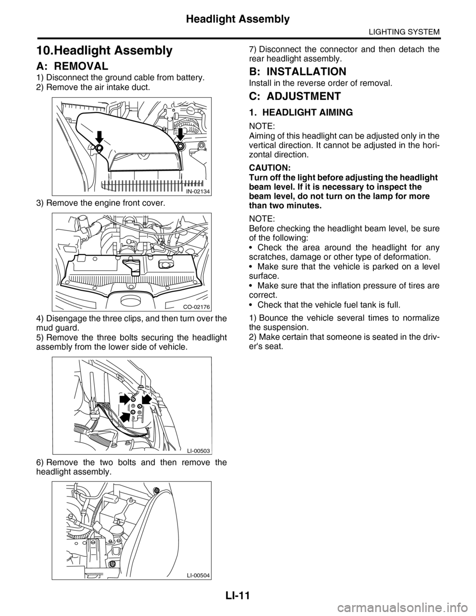
2) Remove the air intake duct.
3) Remove the engine front cover.
4) Disengage the three clips, and then turn over the
mud guard.
5) Remove the three bolts securing the headlight
assembly from the lower side of vehicle.
6) Remove the two bolts and then remove the
headlight assembly.
7) Disconnect the connector and then detach the
rear headlight assembly.
B: INSTALLATION
Install in the reverse order of removal.
C: ADJUSTMENT
1. HEADLIGHT AIMING
NOTE:
Aiming of this headlight can be adjusted only in the
vertical direction. It cannot be adjusted in the hori-
zontal direction.
CAUTION:
Turn off the light before adjusting the headlight
beam level. If it is necessary to inspect the
beam level, do not turn on the lamp for more
than two minutes.
NOTE:
Before checking the headlight beam level, be sure
of the following:
•Check the area around the headlight for any
scratches, damage or other type of deformation.
•Make sure that the vehicle is parked on a level
surface.
•Make sure that the inflation pressure of tires are
correct.
•Check that the vehicle fuel tank is full.
1) Bounce the vehicle several times to normalize
the suspension.
2) Make certain that someone is seated in the driv-
er's seat.
IN-02134
CO-02176
LI-00503
LI-00504
Page 546 of 2453
LI-13
Headlight Bulb
LIGHTING SYSTEM
11.Headlight Bulb
A: REMOVAL
1. HIGH BEAM AND LOW BEAM
CAUTION:
•Because the halogen bulb operates at a high
temperature, dirt and oil on the bulb surface re-
duces the bulb's service life. Hold the flange
portion when replacing the bulb. Never touch
the glass portion.
•Do not leave the headlight without a bulb for
a long time. Dust, moisture, etc. entering the
headlight may affect its performance.
1) Disconnect the ground cable from battery.
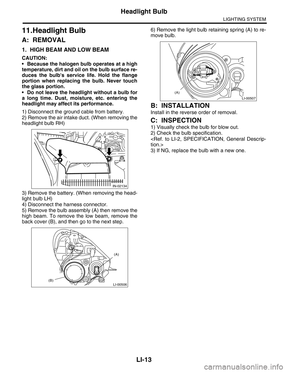
2) Remove the air intake duct. (When removing the
headlight bulb RH)
3) Remove the battery. (When removing the head-
light bulb LH)
4) Disconnect the harness connector.
5) Remove the bulb assembly (A) then remove the
high beam. To remove the low beam, remove the
back cover (B), and then go to the next step.
6) Remove the light bulb retaining spring (A) to re-
move bulb.
B: INSTALLATION
Install in the reverse order of removal.
C: INSPECTION
1) Visually check the bulb for blow out.
2) Check the bulb specification.
3) If NG, replace the bulb with a new one.
IN-02134
LI-00506(B)
(A)
LI-00507
(A)
Page 684 of 2453
SL-55
Immobilizer Antenna
SECURITY AND LOCKS
26.Immobilizer Antenna
A: REMOVAL
1) Disconnect the ground cable from battery.
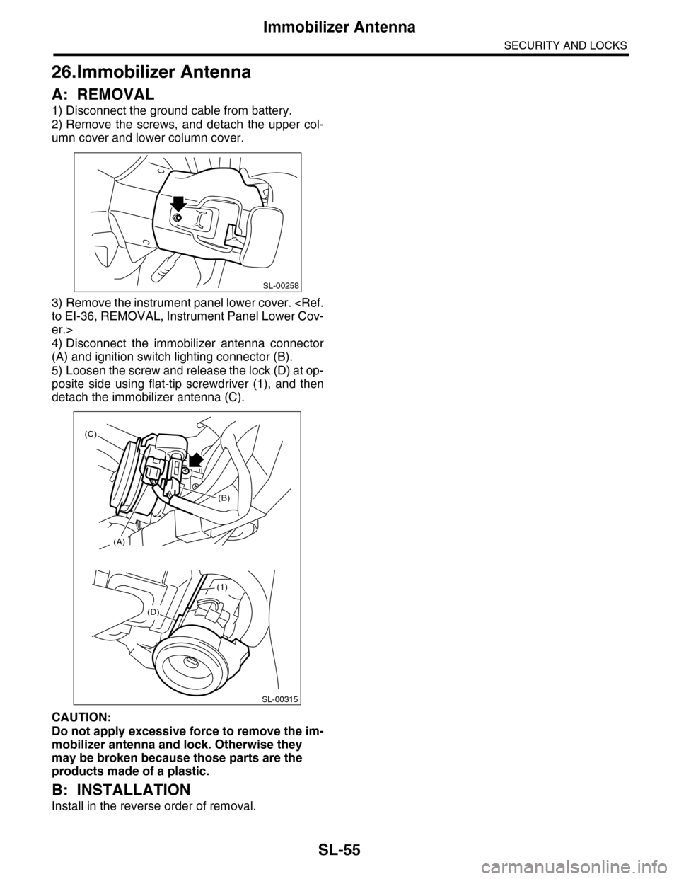
2) Remove the screws, and detach the upper col-
umn cover and lower column cover.
3) Remove the instrument panel lower cover.
er.>
4) Disconnect the immobilizer antenna connector
(A) and ignition switch lighting connector (B).
5) Loosen the screw and release the lock (D) at op-
posite side using flat-tip screwdriver (1), and then
detach the immobilizer antenna (C).
CAUTION:
Do not apply excessive force to remove the im-
mobilizer antenna and lock. Otherwise they
may be broken because those parts are the
products made of a plastic.
B: INSTALLATION
Install in the reverse order of removal.
SL-00258
(D)
(1)
SL-00315
(A)
(C)
(B)
Page 917 of 2453
PS-37
Pipe Assembly
POWER ASSISTED SYSTEM (POWER STEERING)
6. Pipe Assembly
A: REMOVAL
1) Disconnect the ground cable from the battery.
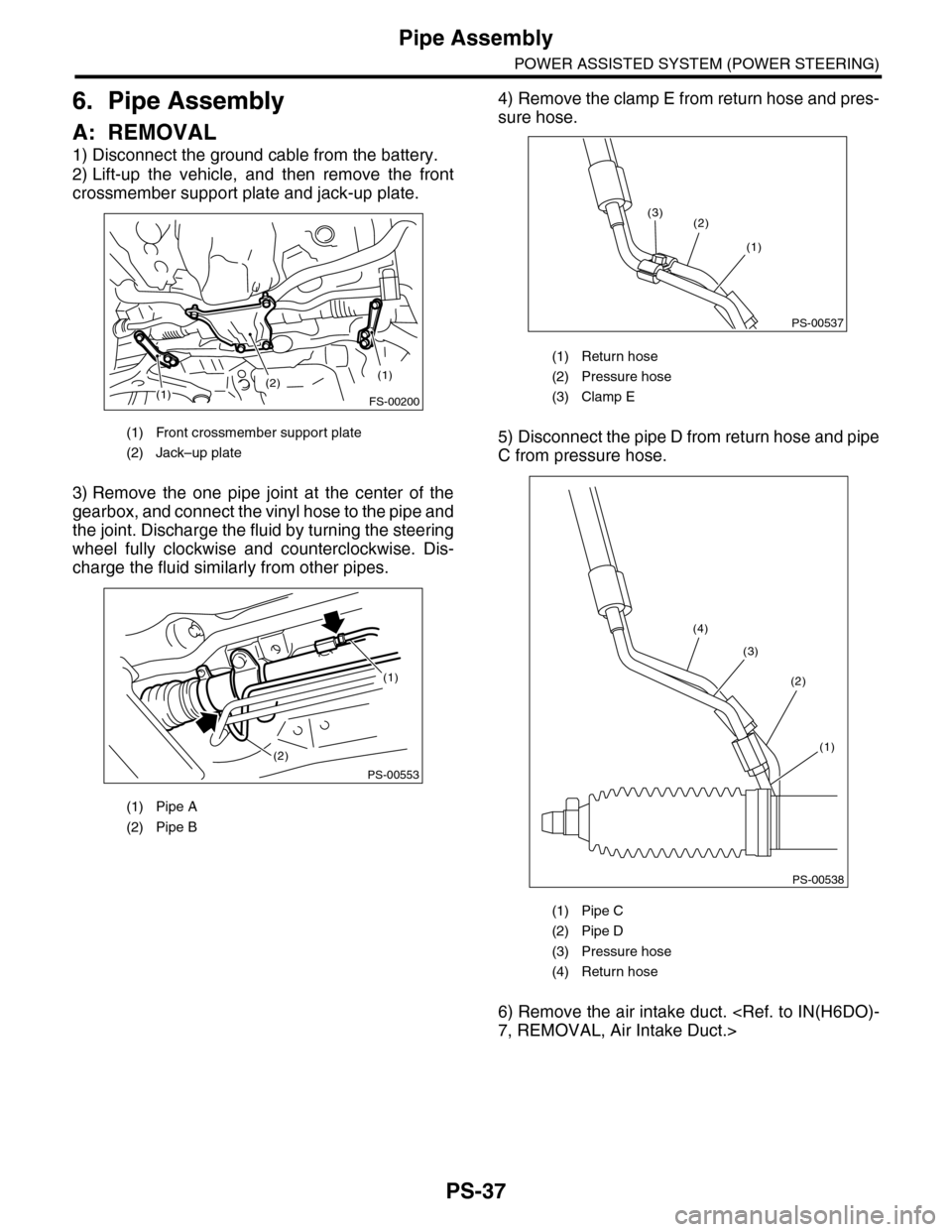
2) Lift-up the vehicle, and then remove the front
crossmember support plate and jack-up plate.
3) Remove the one pipe joint at the center of the
gearbox, and connect the vinyl hose to the pipe and
the joint. Discharge the fluid by turning the steering
wheel fully clockwise and counterclockwise. Dis-
charge the fluid similarly from other pipes.
4) Remove the clamp E from return hose and pres-
sure hose.
5) Disconnect the pipe D from return hose and pipe
C from pressure hose.
6) Remove the air intake duct.
(1) Front crossmember support plate
(2) Jack–up plate
(1) Pipe A
(2) Pipe B
(2)(1)
(1)
FS-00200
(2)
PS-00553
(1)
(1) Return hose
(2) Pressure hose
(3) Clamp E
(1) Pipe C
(2) Pipe D
(3) Pressure hose
(4) Return hose
PS-00537
(3)
(1)
(2)
PS-00538
(4)
(3)
(2)
(1)
Page 921 of 2453
PS-41
Oil Pump
POWER ASSISTED SYSTEM (POWER STEERING)
7. Oil Pump
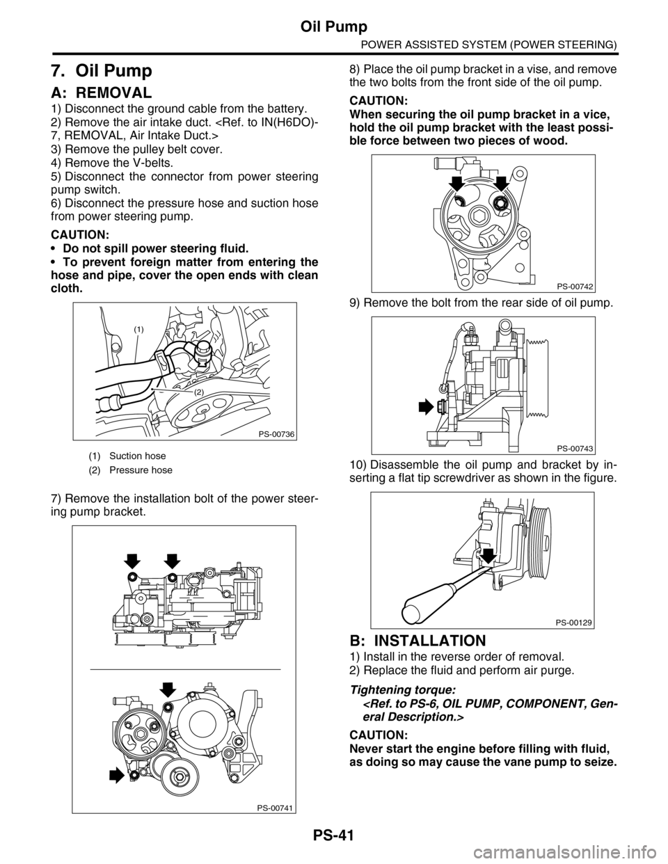
A: REMOVAL
1) Disconnect the ground cable from the battery.
2) Remove the air intake duct.
3) Remove the pulley belt cover.
4) Remove the V-belts.
5) Disconnect the connector from power steering
pump switch.
6) Disconnect the pressure hose and suction hose
from power steering pump.
CAUTION:
•Do not spill power steering fluid.
•To prevent foreign matter from entering the
hose and pipe, cover the open ends with clean
cloth.
7) Remove the installation bolt of the power steer-
ing pump bracket.
8) Place the oil pump bracket in a vise, and remove
the two bolts from the front side of the oil pump.
CAUTION:
When securing the oil pump bracket in a vice,
hold the oil pump bracket with the least possi-
ble force between two pieces of wood.
9) Remove the bolt from the rear side of oil pump.
10) Disassemble the oil pump and bracket by in-
serting a flat tip screwdriver as shown in the figure.
B: INSTALLATION
1) Install in the reverse order of removal.
2) Replace the fluid and perform air purge.
Tightening torque:
CAUTION:
Never start the engine before filling with fluid,
as doing so may cause the vane pump to seize.
(1) Suction hose
(2) Pressure hose
PS-00736
(1)
(2)
PS-00741
PS-00742
PS-00743
PS-00129
Page 925 of 2453
PS-45
Oil Pump
POWER ASSISTED SYSTEM (POWER STEERING)
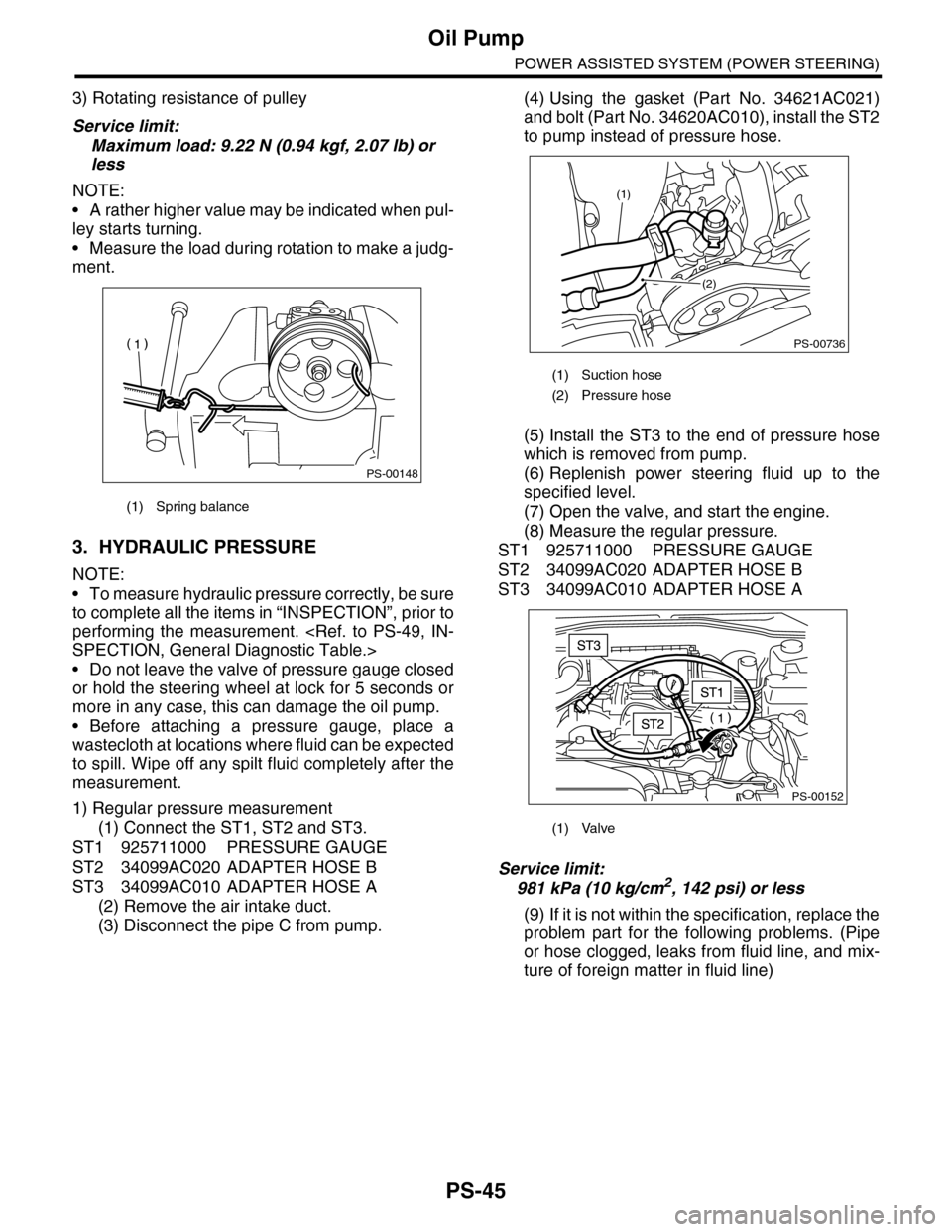
3) Rotating resistance of pulley
Service limit:
Maximum load: 9.22 N (0.94 kgf, 2.07 lb) or
less
NOTE:
•A rather higher value may be indicated when pul-
ley starts turning.
•Measure the load during rotation to make a judg-
ment.
3. HYDRAULIC PRESSURE
NOTE:
•To measure hydraulic pressure correctly, be sure
to complete all the items in “INSPECTION”, prior to
performing the measurement.
•Do not leave the valve of pressure gauge closed
or hold the steering wheel at lock for 5 seconds or
more in any case, this can damage the oil pump.
•Before attaching a pressure gauge, place a
wastecloth at locations where fluid can be expected
to spill. Wipe off any spilt fluid completely after the
measurement.
1) Regular pressure measurement
(1) Connect the ST1, ST2 and ST3.
ST1 925711000 PRESSURE GAUGE
ST2 34099AC020 ADAPTER HOSE B
ST3 34099AC010 ADAPTER HOSE A
(2) Remove the air intake duct.
(3) Disconnect the pipe C from pump.
(4) Using the gasket (Part No. 34621AC021)
and bolt (Part No. 34620AC010), install the ST2
to pump instead of pressure hose.
(5) Install the ST3 to the end of pressure hose
which is removed from pump.
(6) Replenish power steering fluid up to the
specified level.
(7) Open the valve, and start the engine.
(8) Measure the regular pressure.
ST1 925711000 PRESSURE GAUGE
ST2 34099AC020 ADAPTER HOSE B
ST3 34099AC010 ADAPTER HOSE A
Service limit:
981 kPa (10 kg/cm2, 142 psi) or less
(9) If it is not within the specification, replace the
problem part for the following problems. (Pipe
or hose clogged, leaks from fluid line, and mix-
ture of foreign matter in fluid line)
(1) Spring balance
PS-00148
(1) Suction hose
(2) Pressure hose
(1) Valve
PS-00736
(1)
(2)
PS-00152