SUBARU TRIBECA 2009 1.G Service Workshop Manual
Manufacturer: SUBARU, Model Year: 2009, Model line: TRIBECA, Model: SUBARU TRIBECA 2009 1.GPages: 2453, PDF Size: 46.32 MB
Page 1001 of 2453
VDC(diag)-9
General Description
VEHICLE DYNAMICS CONTROL (VDC) (DIAGNOSTICS)
3. General Description
A: CAUTION
1. SRS AIRBAG SYSTEM
Airbag system wiring harness is routed near the
ABS wheel speed sensor and VDCCM&H/U.
CAUTION:
•All airbag system wiring harness and con-
nectors are colored yellow. Do not use the elec-
trical test equipment on these circuits.
•Be careful not to damage the airbag system
wiring harness when servicing the ABS wheel
speed sensor and VDCCM&H/U.
B: INSPECTION
Before performing diagnosis, check the following
items which might affect VDC problems.
1. BATTERY
Measure the battery voltage and check electrolyte.
Standard voltage: 12 V or more
Specific gravity: 1.260 or more
2. GROUND
Check the tightening torque of ground (GB-7) bolt
of VDC.
Tightening torque:
13 N·m (1.3 kgf-m, 9.6 ft-lb)
3. BRAKE FLUID
1) Check the brake fluid level.
2) Check the brake fluid for leaks.
4. HYDRAULIC UNIT
Check the hydraulic unit.
•With brake tester
TESTER, INSPECTION, VDC Control Module &
Hydraulic Control Unit (VDCCM&H/U).>
•Without brake tester
USING A PRESSURE GAUGE, INSPECTION,
VDC Control Module & Hydraulic Control Unit (VD-
CCM&H/U).>
5. BRAKE DRAG
Check for brake drag.
6. BRAKE PAD AND ROTOR
Check the brake pad and rotor.
•Front
•Rear
7. TIRE
Check the tire specifications, tire wear and air pres-
sure.
Page 1002 of 2453
VDC(diag)-10
General Description
VEHICLE DYNAMICS CONTROL (VDC) (DIAGNOSTICS)
C: PREPARATION TOOL
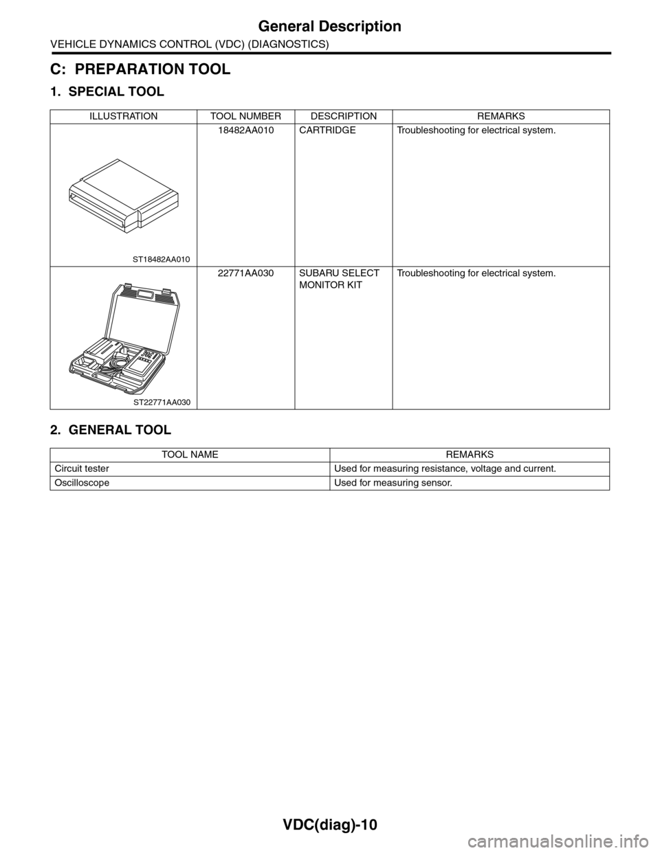
1. SPECIAL TOOL
2. GENERAL TOOL
ILLUSTRATION TOOL NUMBER DESCRIPTION REMARKS
18482AA010 CARTRIDGE Troubleshooting for electrical system.
22771AA030 SUBARU SELECT
MONITOR KIT
Tr o u b l e s h o o t i n g f o r e l e c t r i c a l s y s t e m .
TOOL NAME REMARKS
Circuit tester Used for measuring resistance, voltage and current.
Oscilloscope Used for measuring sensor.
ST18482AA010
ST22771AA030
Page 1003 of 2453
VDC(diag)-11
Electrical Component Location
VEHICLE DYNAMICS CONTROL (VDC) (DIAGNOSTICS)
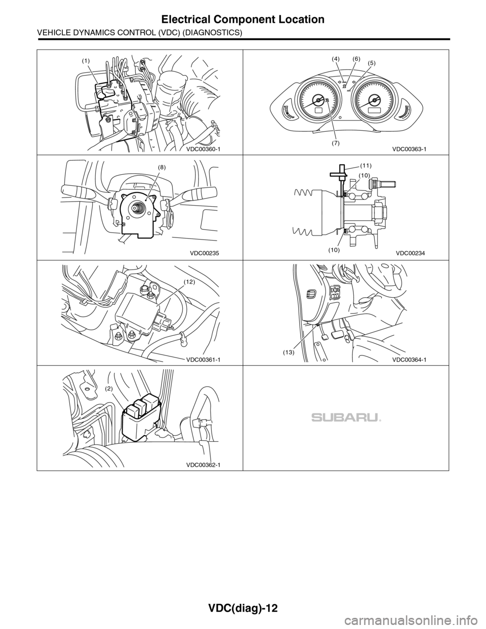
4. Electrical Component Location
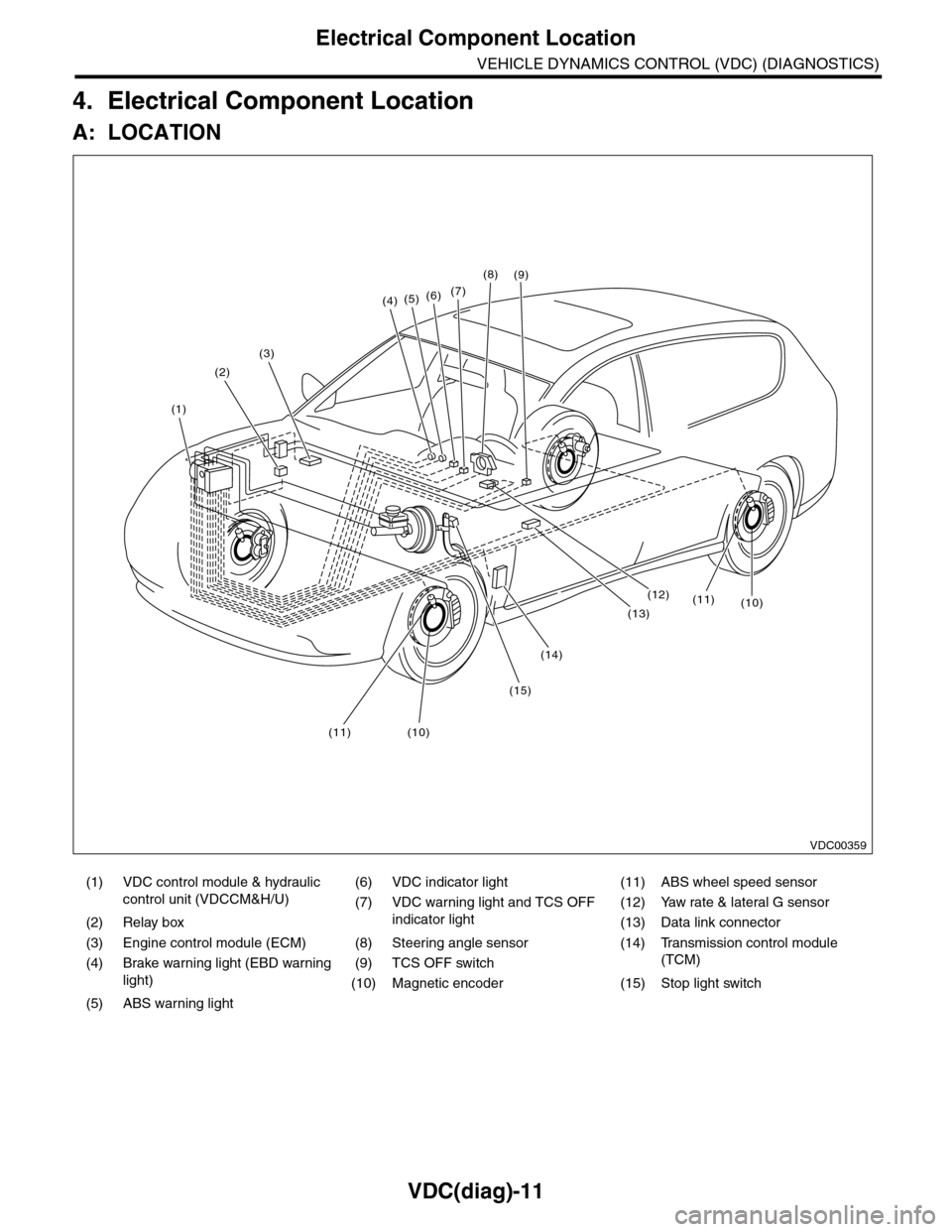
A: LOCATION
(1) VDC control module & hydraulic
control unit (VDCCM&H/U)
(6) VDC indicator light (11) ABS wheel speed sensor
(7) VDC warning light and TCS OFF
indicator light
(12) Yaw rate & lateral G sensor
(2) Relay box (13) Data link connector
(3) Engine control module (ECM) (8) Steering angle sensor (14) Transmission control module
(TCM)(4) Brake warning light (EBD warning
light)
(9) TCS OFF switch
(10) Magnetic encoder (15) Stop light switch
(5) ABS warning light
(4)(5)(6)(7)
(8)
(1)
(2)
(3)
(15)
(14)
(12)
(13)
(11)(10)
(11)(10)
(9)
VDC00359
Page 1004 of 2453
VDC(diag)-12
Electrical Component Location
VEHICLE DYNAMICS CONTROL (VDC) (DIAGNOSTICS)
VDC00360-1
(1)
VDC00363-1
(4)
(7)
(6)(5)
(8)
VDC00235VDC00234
(11)
(10)
(10)
VDC00361-1
(12)
VDC00364-1(13)
VDC00362-1
(2)
Page 1005 of 2453
VDC(diag)-13
Control Module I/O Signal
VEHICLE DYNAMICS CONTROL (VDC) (DIAGNOSTICS)
5. Control Module I/O Signal
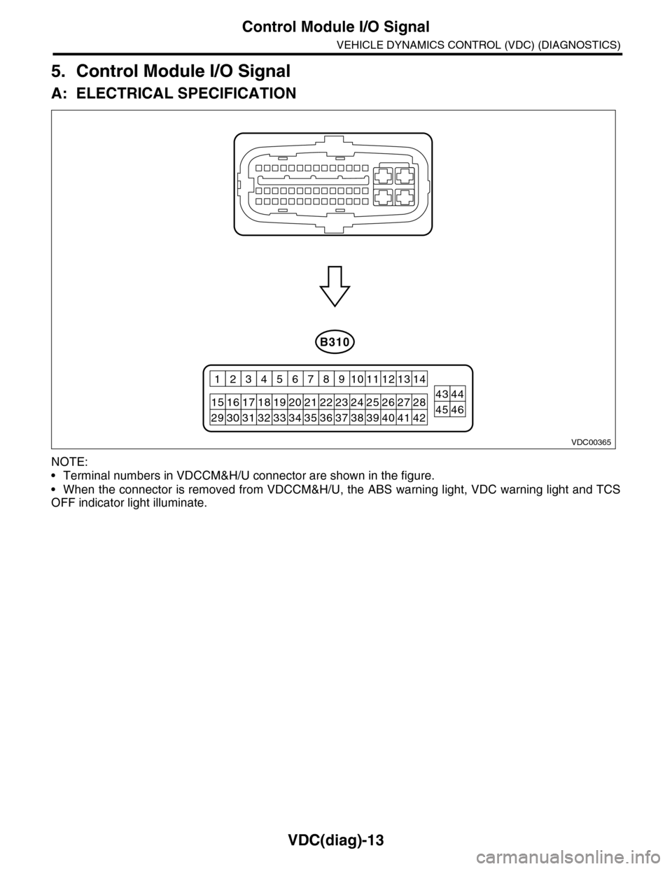
A: ELECTRICAL SPECIFICATION
NOTE:
•Terminal numbers in VDCCM&H/U connector are shown in the figure.
•When the connector is removed from VDCCM&H/U, the ABS warning light, VDC warning light and TCS
OFF indicator light illuminate.
VDC00365
B310
2627284344252423
12131411109
201918171615
43218765
2122
40414245463938373433323130293536
Page 1006 of 2453
VDC(diag)-14
Control Module I/O Signal
VEHICLE DYNAMICS CONTROL (VDC) (DIAGNOSTICS)
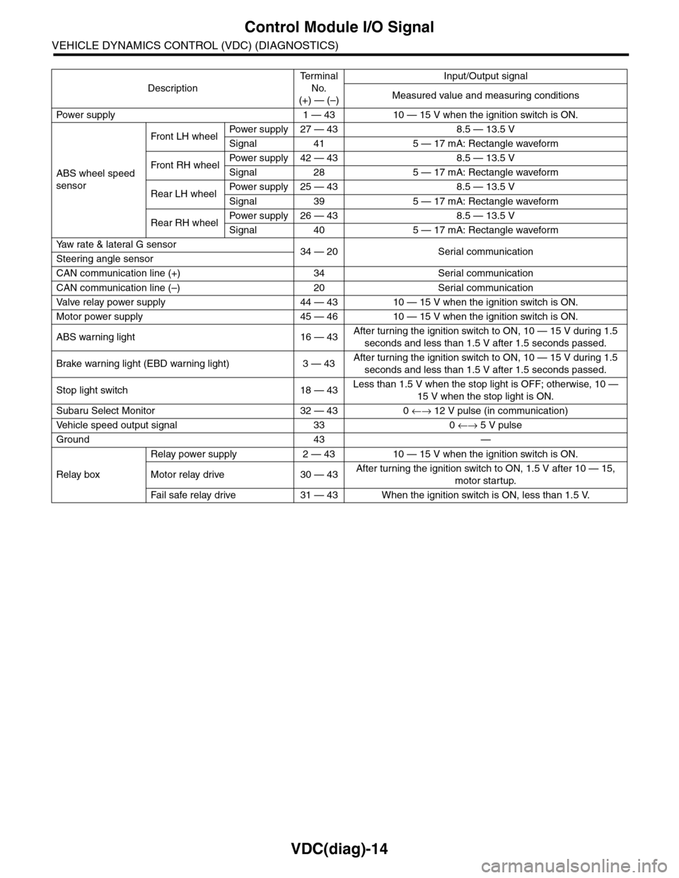
Description
Te r m i n a l
No.
(+) — (–)
Input/Output signal
Measured value and measuring conditions
Pow er s up p ly 1 — 43 10 — 15 V w h e n t h e i gn i t io n sw it ch i s ON .
ABS wheel speed
sensor
Front LH wheelPowe r s u pp ly 27 — 4 3 8 . 5 — 1 3. 5 V
Signal 41 5 — 17 mA: Rectangle waveform
Front RH wheelPower supply 42 — 43 8.5 — 13.5 V
Signal 28 5 — 17 mA: Rectangle waveform
Rear LH wheelPower supply 25 — 43 8.5 — 13.5 V
Signal 39 5 — 17 mA: Rectangle waveform
Rear RH wheelPower supply 26 — 43 8.5 — 13.5 V
Signal 40 5 — 17 mA: Rectangle waveform
Ya w r a t e & l a t e r a l G s e n s o r34 — 20 Serial communicationSteering angle sensor
CAN communication line (+) 34 Serial communication
CAN communication line (–) 20 Serial communication
Valve relay power supply 44 — 43 10 — 15 V when the ignition switch is ON.
Motor power supply 45 — 46 10 — 15 V when the ignition switch is ON.
ABS warning light 16 — 43After turning the ignition switch to ON, 10 — 15 V during 1.5
seconds and less than 1.5 V after 1.5 seconds passed.
Brake warning light (EBD warning light) 3 — 43After turning the ignition switch to ON, 10 — 15 V during 1.5
seconds and less than 1.5 V after 1.5 seconds passed.
Stop light switch 18 — 43Less than 1.5 V when the stop light is OFF; otherwise, 10 —
15 V when the stop light is ON.
Subaru Select Monitor 32 — 43 0 ←→ 12 V pulse (in communication)
Ve h i c l e s p e e d o u t p u t s i g n a l 3 3 0 ←→ 5 V pulse
Ground 43 —
Relay box
Relay power supply 2 — 43 10 — 15 V when the ignition switch is ON.
Motor relay drive 30 — 43After turning the ignition switch to ON, 1.5 V after 10 — 15,
motor startup.
Fa i l s afe r e lay d r ive 31 — 4 3 W he n t h e i g ni t io n swit c h i s ON, l es s t ha n 1 . 5 V.
Page 1007 of 2453
VDC(diag)-15
Control Module I/O Signal
VEHICLE DYNAMICS CONTROL (VDC) (DIAGNOSTICS)
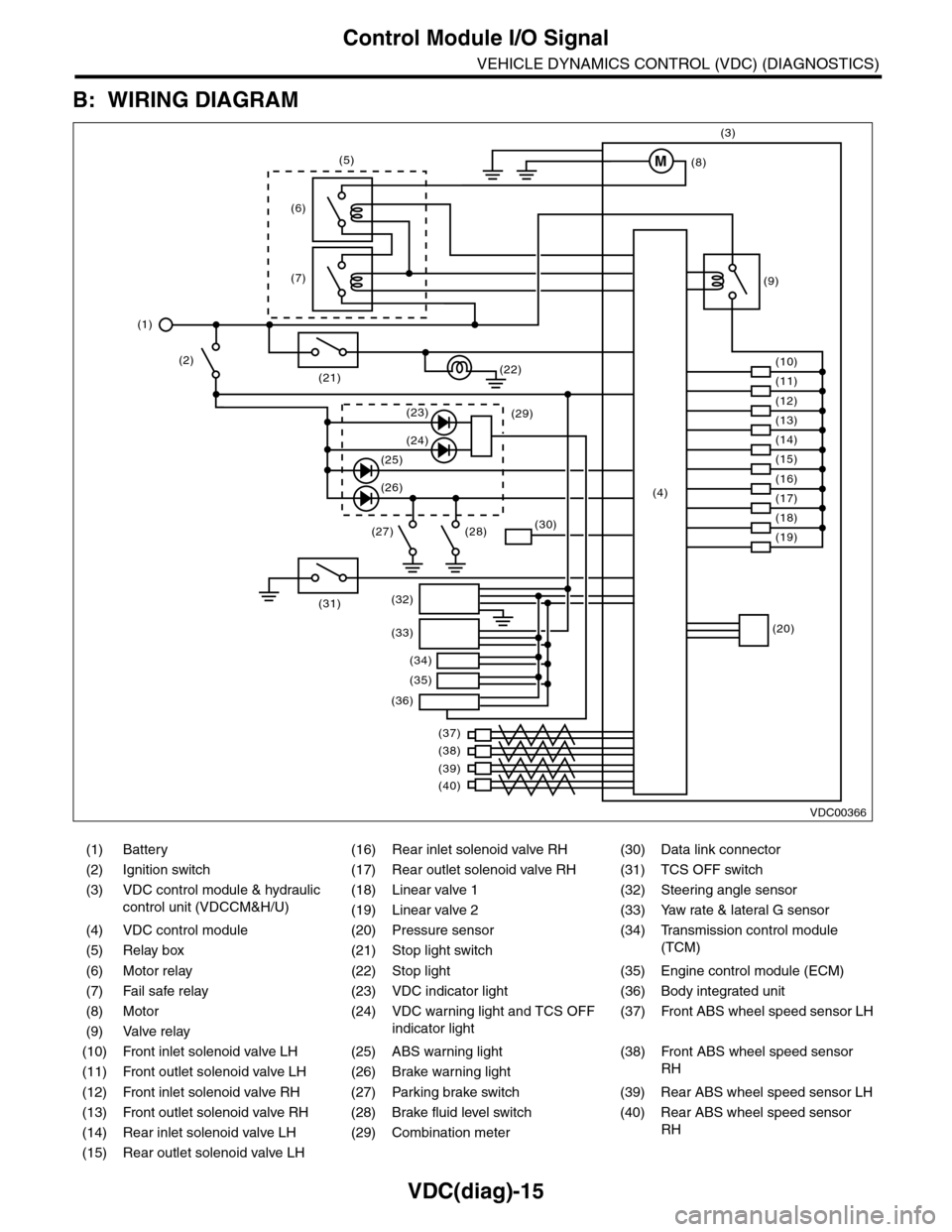
B: WIRING DIAGRAM
(1) Battery (16) Rear inlet solenoid valve RH (30) Data link connector
(2) Ignition switch (17) Rear outlet solenoid valve RH (31) TCS OFF switch
(3) VDC control module & hydraulic
control unit (VDCCM&H/U)
(18) Linear valve 1 (32) Steering angle sensor
(19) Linear valve 2 (33) Yaw rate & lateral G sensor
(4) VDC control module (20) Pressure sensor (34)
Tr a n s m i s s i o n c o n t r o l m o d u l e
(TCM)(5) Relay box (21) Stop light switch
(6) Motor relay (22) Stop light (35) Engine control module (ECM)
(7) Fail safe relay (23) VDC indicator light (36) Body integrated unit
(8) Motor (24) VDC warning light and TCS OFF
indicator light
(37)
Fr o nt A B S w he e l sp ee d se n so r L H
(9) Valve relay
(10) Front inlet solenoid valve LH (25) ABS warning light (38)
Fr o nt A B S w he e l sp e ed se n so r
RH(11) Front outlet solenoid valve LH (26) Brake warning light
(12) Front inlet solenoid valve RH (27) Parking brake switch (39) Rear ABS wheel speed sensor LH
(13) Front outlet solenoid valve RH (28) Brake fluid level switch (40) Rear ABS wheel speed sensor
RH(14) Rear inlet solenoid valve LH (29) Combination meter
(15) Rear outlet solenoid valve LH
VDC00366
M
(17)(4)(16)
(19)
(20)
(18)
(38)
(37)
(32)
(33)
(36)
(34)
(35)
(40)
(39)
(15)
(14)
(13)
(12)
(7)
(22)(21)
(31)
(23)(29)
(24)
(25)
(26)
(27) (28)(30)
(1)
(2)
(6)
(11)
(10)
(9)
(8)
(3)
(5)
Page 1008 of 2453
VDC(diag)-16
Subaru Select Monitor
VEHICLE DYNAMICS CONTROL (VDC) (DIAGNOSTICS)
6. Subaru Select Monitor
A: OPERATION
1. READ DIAGNOSTIC TROUBLE CODE
(DTC)
1) Prepare the Subaru Select Monitor kit.
TOOL, General Description.>
2) Connect the diagnosis cable to Subaru Select
Monitor.
3) Insert the cartridge to the Subaru Select Monitor.
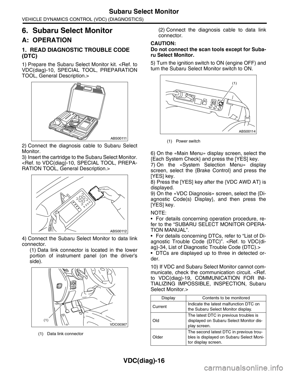
4) Connect the Subaru Select Monitor to data link
connector.
(1) Data link connector is located in the lower
portion of instrument panel (on the driver's
side).
(2) Connect the diagnosis cable to data link
connector.
CAUTION:
Do not connect the scan tools except for Suba-
ru Select Monitor.
5) Turn the ignition switch to ON (engine OFF) and
turn the Subaru Select Monitor switch to ON.
6) On the «Main Menu» display screen, select the
{Each System Check} and press the [YES] key.
7) On the «System Selection Menu» display
screen, select the {Brake Control} and press the
[YES] key.
8) Press the [YES] key after the {VDC AWD AT} is
displayed.
9) On the «VDC Diagnosis» screen, select the {Di-
agnostic Code(s) Display}, and then press the
[YES] key.
NOTE:
•For details concerning operation procedure, re-
fer to the “SUBARU SELECT MONITOR OPERA-
TION MANUAL”.
•For details concerning DTCs, refer to “List of Di-
agnostic Trouble Code (DTC)”.
•DTCs are displayed up to three in detected or-
der.
10) If VDC and Subaru Select Monitor cannot com-
municate, check the communication circuit.
TIALIZING IMPOSSIBLE, INSPECTION, Subaru
Select Monitor.>
(1) Data link connector
ABS00111
ABS00112
VDC00367(1)
(1) Power switch
Display Contents to be monitored
CurrentIndicate the latest malfunction DTC on
the Subaru Select Monitor display.
Old
The latest DTC in previous troubles is
displayed on Subaru Select Monitor dis-
play screen.
Older
The second latest DTC in previous trou-
bles is displayed on Subaru Select Moni-
tor display screen.
ABS00114
(1)
Page 1009 of 2453
![SUBARU TRIBECA 2009 1.G Service Workshop Manual VDC(diag)-17
Subaru Select Monitor
VEHICLE DYNAMICS CONTROL (VDC) (DIAGNOSTICS)
2. READ CURRENT DATA
1) On the «Main Menu» display screen, select the {Each System Check} and press the [YES] key.
2) SUBARU TRIBECA 2009 1.G Service Workshop Manual VDC(diag)-17
Subaru Select Monitor
VEHICLE DYNAMICS CONTROL (VDC) (DIAGNOSTICS)
2. READ CURRENT DATA
1) On the «Main Menu» display screen, select the {Each System Check} and press the [YES] key.
2)](/img/17/7322/w960_7322-1008.png)
VDC(diag)-17
Subaru Select Monitor
VEHICLE DYNAMICS CONTROL (VDC) (DIAGNOSTICS)
2. READ CURRENT DATA
1) On the «Main Menu» display screen, select the {Each System Check} and press the [YES] key.
2) On the «System Selection Menu» display screen, select the {Brake Control} and press the [YES] key.
3) Press the [YES] key after {VDC AWD AT} is displayed.
4) On the «Brake Control Diagnosis» display screen, select the {Current Data Display/Save}, and then press
the [YES] key.
5) On the «Display Menu» screen, select the data display method and press the [YES] key.
6) Using a scroll key, scroll the display screen up or down until necessary data is shown.
•A list of the support data is shown in the following table.
NOTE:
For details concerning operation procedure, refer to the “SUBARU SELECT MONITOR OPERATION MAN-
UAL”.
Display Contents to be monitored Unit of measure
FR Wheel SpeedWheel speed detected by front ABS wheel speed sensor RH is dis-
played.km/h or MPH
FL Wheel SpeedWheel speed detected by front ABS wheel speed sensor LH is dis-
played.km/h or MPH
RR Wheel SpeedWheel speed detected by rear ABS wheel speed sensor RH is dis-
played.km/h or MPH
RL Wheel SpeedWheel speed detected by rear ABS wheel speed sensor LH is dis-
played.km/h or MPH
Fr o nt / Re ar G S e ns o r Ve h ic le f r on t / re a r ac ce le ra t io n d e te c te d by G se n so r is d i sp layed .m/s2
Lateral G Sensor Vehicle lateral acceleration detected by G sensor is displayed.m/s2
IG power supply voltage Voltage supplied to VDCCM&H/U is displayed. V
Steering Angle Sensor Steering angle detected by steering angle sensor is displayed. deg
Ya w R a t e S e n s o r V e h i c l e a n g u l a r s p e e d d e t e c t e d b y y a w r a t e s e n s o r i s d i s p l a y e d . d e g / s
Pressure Sensor Brake fluid pressure detected by pressure sensor is displayed. bar
ABS Control Flag ABS control condition is displayed. ON or OFF
EBD Control Flag EBD control condition is displayed. ON or OFF
Brake Switch Brake ON/OFF is displayed. ON or OFF
ABS Warning Light ON operation of the ABS warning light is displayed. ON or OFF
EBD Warning Light ON operation of the EBD warning light is displayed. ON or OFF
Motor Relay Signal Motor relay operation signal is displayed. ON or OFF
Motor Relay Monitor Motor relay monitor signal is displayed. ON or OFF
TCS Control Flag TCS control condition is displayed. ON or OFF
Va l ve R e l ay S i g n a l Va l v e r e l ay o p e r a t i o n s i g n a l i s d i s p l ay e d . O N o r O F F
VDC Control Flag VDC control condition is displayed. ON or OFF
VDC Warning Light ON operation of the VDC warning light is displayed. ON or OFF
OFF Light ON/OFF condition of TCS OFF indicator light is displayed. ON or OFF
E/G Control Prohibited Flag Engine control command signal is displayed. 1 or 0
OFF Switch Signal Operation condition of TCS OFF switch is displayed. ON or OFF
Motor Fail Safe Relay Drive
SignalMotor fail safe relay drive signal is displayed. ON or OFF
Page 1010 of 2453
![SUBARU TRIBECA 2009 1.G Service Workshop Manual VDC(diag)-18
Subaru Select Monitor
VEHICLE DYNAMICS CONTROL (VDC) (DIAGNOSTICS)
3. CLEAR MEMORY MODE
1) On the «Main Menu», select the {2. Each Sys-
tem Check} and press the [YES] key.
2) On SUBARU TRIBECA 2009 1.G Service Workshop Manual VDC(diag)-18
Subaru Select Monitor
VEHICLE DYNAMICS CONTROL (VDC) (DIAGNOSTICS)
3. CLEAR MEMORY MODE
1) On the «Main Menu», select the {2. Each Sys-
tem Check} and press the [YES] key.
2) On](/img/17/7322/w960_7322-1009.png)
VDC(diag)-18
Subaru Select Monitor
VEHICLE DYNAMICS CONTROL (VDC) (DIAGNOSTICS)
3. CLEAR MEMORY MODE
1) On the «Main Menu», select the {2. Each Sys-
tem Check} and press the [YES] key.
2) On the «System Selection Menu» display
screen, select the {Brake Control} and press the
[YES] key.
3) Press the [YES] key after {VDC AWD AT} is dis-
played.
4) On the «Brake Control Diagnosis» display
screen, select the {Memory Clear} and press the
[YES] key.
5) When “Done” and “Turn ignition switch OFF” are
shown on the display screen, turn the Subaru Se-
lect Monitor and ignition switch to OFF.
NOTE:
For details concerning operation procedure, refer
to the “SUBARU SELECT MONITOR OPERATION
MANUAL”.
4. SEQUENCE CONTROL
5. FREEZE FRAME DATA
NOTE:
•Data stored at the time of trouble occurrence is
shown on display.
•Each time trouble occurs, the latest information
is stored in the freeze frame data in memory.
Display Contents to be monitored
Clear memory? DTC deleting function
Display Contents to be monitoredReference tar-
get
ABS
sequence
control
Operate the valve and
pump motor continuously
to perform the ABS
sequence control.
Sequence Con-
trol.>
VDC
sequence
control
Operate the valve and
pump motor continuously
to perform the VDC
sequence control.
Sequence Con-
trol.>
Display Contents to be monitored
IG CounterNumber of times ignition switch turned to
ON is displayed.
DTC The recorded failure code is displayed.
FR Wheel
Speed
Wheel speed detected by front ABS
wheel speed sensor RH is displayed in
km/h or MPH.
FL Wheel Speed
Wheel speed detected by front ABS
wheel speed sensor LH is displayed in
km/h or MPH.
RR Wheel
Speed
Wheel speed detected by rear ABS
wheel speed sensor RH is displayed in
km/h or MPH.
RL Wheel
Speed
Wheel speed detected by rear ABS
wheel speed sensor LH is displayed in
km/h or MPH.
Ve h i c l e S p e e dVe h i c l e s p e e d c a l c u l a t e d b y V D C c o n t r o l
module is displayed.
G Sensor First
ShaftThe sensor value for a 45° angle crossed
2 axis G sensor is displayed.G Sensor Sec-
ond Shaft
Ya w R a t e S e n -
sor
Ve h i c l e a n g u l a r s p e e d d e t e c t e d b y y a w
rate sensor is displayed.
IG power supply
voltage
Vo l t a g e s u p p l i e d t o V D C c o n t r o l m o d u l e
is displayed.
Steering Angle
Sensor
Steering angle detected by steering
angle sensor is displayed.
Pressure sen-
sor output
Brake fluid pressure detected by pres-
sure sensor is displayed.
Engine SpeedEngine speed on malfunction occur-
rence is displayed.
Acceleration
Opening AngleAcceleration opening is displayed.
Gear positionGear position on malfunction occurrence
is displayed.
Steering Angle
Sensor Malfunc-
tion Code
The recorded steering angle sensor fail-
ure code is displayed?
ABS Control
FlagABS control condition is displayed.
EBD Control
FlagEBD control condition is displayed.
Brake Switch Brake ON/OFF is displayed.
TCS Control
FlagTCS control condition is displayed.
VDC Control
FlagVDC control condition is displayed.
E/G Control Flag
Absolute angle
recognition flag
Whether the absolute angle was deter-
mined is displayed.
OFF Switch Sig-
nal
Operation condition of TCS OFF switch
is displayed.