SUBARU TRIBECA 2009 1.G Service Workshop Manual
Manufacturer: SUBARU, Model Year: 2009, Model line: TRIBECA, Model: SUBARU TRIBECA 2009 1.GPages: 2453, PDF Size: 46.32 MB
Page 1091 of 2453
VDC-10
VDC Control Module & Hydraulic Control Unit (VDCCM&H/U)
VEHICLE DYNAMICS CONTROL (VDC)
6) When the hydraulic unit begins to work, first the
FL side performs compression, hold, and decom-
pression, and then the FR side performs compres-
sion, hold, and decompression.
7) Read values indicated on the pressure gauge
and check if the fluctuation of the values between
decompression and compression meets specifica-
tion. Depress the brake pedal and check that it is
not abnormally hard, and tightness is normal.
8) Disconnect the pressure gauges from FL and FR
caliper bodies.
9) Install the air bleeder screws of FL and FR cali-
per bodies.
10) Remove the air bleeder screws from RL and
RR caliper bodies.
11) Connect two pressure gauges to RL and RR
caliper bodies.
12) Bleed air from RL and RR caliper bodies, and
pressure gauge.
13) Perform VDC sequence control.
14) When the hydraulic unit begins to work, first the
RR side performs compression, hold, and decom-
pression, and then the RL side performs compres-
sion, hold, and decompression.
15) Read the values indicated on the pressure
gauges and check if it is within specification. De-
press the brake pedal and check that it is not abnor-
mally hard, and tightness is normal.
16) Disconnect the pressure gauge from the RL
and RR caliper bodies.
17) Install the air bleeder screws of RL and RR cal-
iper bodies.
18) Bleed air from the brake line.
4. CHECK HYDRAULIC UNIT VDC OPERA-
TION WITH BRAKE TESTER
1) Set wheels other than the one to measure free
rollers.
2) Prepare to operate the VDC sequence control.
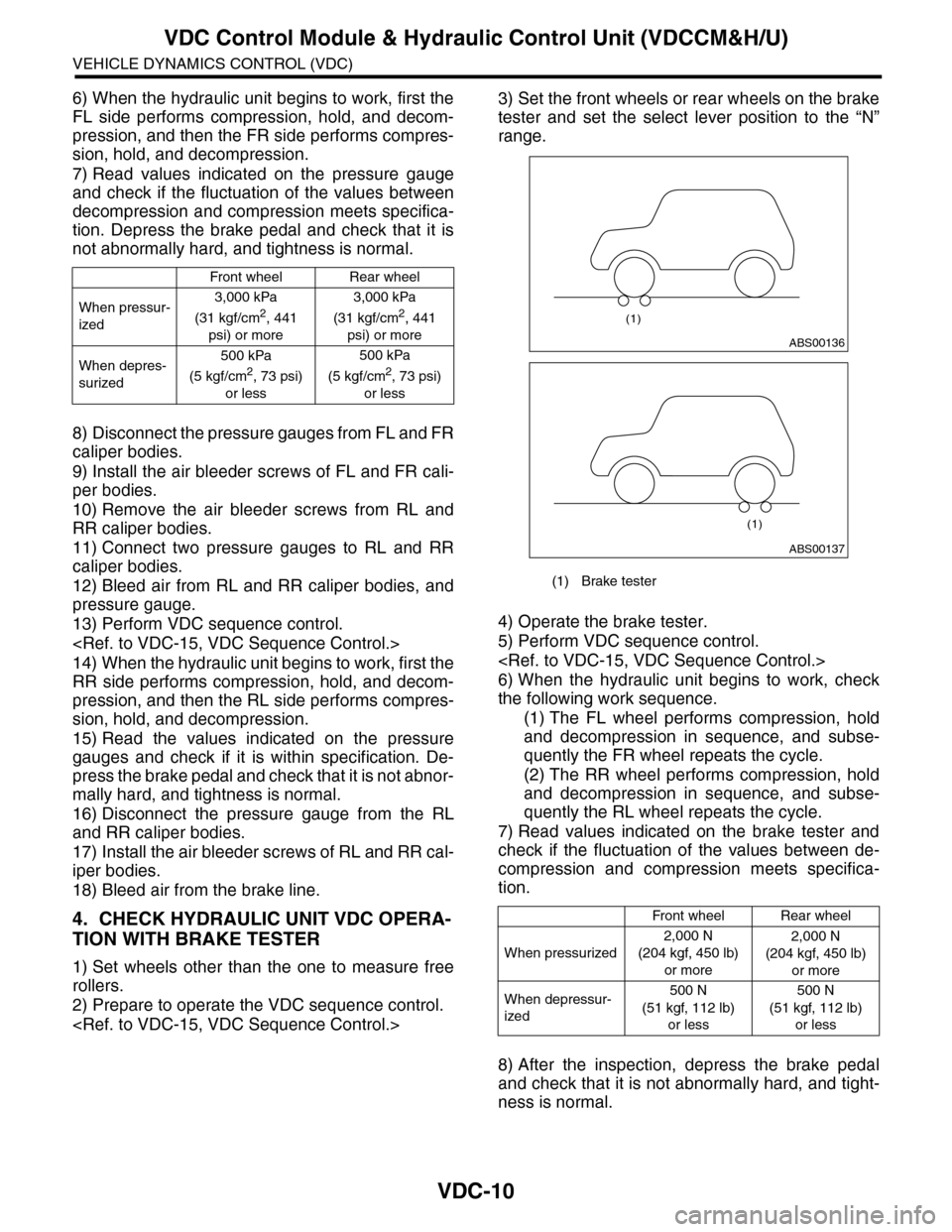
3) Set the front wheels or rear wheels on the brake
tester and set the select lever position to the “N”
range.
4) Operate the brake tester.
5) Perform VDC sequence control.
6) When the hydraulic unit begins to work, check
the following work sequence.
(1) The FL wheel performs compression, hold
and decompression in sequence, and subse-
quently the FR wheel repeats the cycle.
(2) The RR wheel performs compression, hold
and decompression in sequence, and subse-
quently the RL wheel repeats the cycle.
7) Read values indicated on the brake tester and
check if the fluctuation of the values between de-
compression and compression meets specifica-
tion.
8) After the inspection, depress the brake pedal
and check that it is not abnormally hard, and tight-
ness is normal.
Front wheelRear wheel
When pressur-
ized
3,000 kPa
(31 kgf/cm2, 441
psi) or more
3,000 kPa
(31 kgf/cm2, 441
psi) or more
When depres-
surized
500 kPa
(5 kgf/cm2, 73 psi)
or less
500 kPa
(5 kgf/cm2, 73 psi)
or less
(1) Brake tester
Front wheelRear wheel
When pressurized
2,000 N
(204 kgf, 450 lb)
or more
2,000 N
(204 kgf, 450 lb)
or more
When depressur-
ized
500 N
(51 kgf, 112 lb)
or less
500 N
(51 kgf, 112 lb)
or less
ABS00136
(1)
ABS00137
(1)
Page 1092 of 2453
VDC-11
VDC Control Module & Hydraulic Control Unit (VDCCM&H/U)
VEHICLE DYNAMICS CONTROL (VDC)
D: ADJUSTMENT
When the following replacement, removal and in-
stallation are performed, be sure to perform center-
ing of the steering angle sensor and zero point
setting of the yaw rate & G sensor.
•VDCCM&H/U
•Steering angle sensor
•Yaw rate & lateral G sensor
•Steering wheel parts (Including airbag)
•Suspension parts
•Wheel alignment adjustment
1) Park the vehicle straight on a level surface. (En-
gine operation in the “P” or “N” range)
2) Check that steering wheel is positioned at the
center. (When the center position is not correct, ad-
just the wheel alignment.)
3) Set the Subaru Select Monitor to the vehicle,
and select {Set up mode for Neutral of Steering An-
gle Sensor & Lateral G Sensor 0 point} in the
“Function check sequence” screen. (Follow the
procedures shown in the display.)
4) On the “Brake Control System” display screen,
select {Current Data Display & Save}, and check
that the steering angle sensor shows “0 deg”.
5) When the “0 deg” is not displayed, repeat the
above steps and check that the “0 deg” is dis-
played.
6) Drive the vehicle for 10 minutes, and check that
the ABS and VDC warning light is not illuminated.
7) Check that there is no unnecessary VDC opera-
tion or steering control loss. If there is a problem,
repeat the steps above.
Page 1093 of 2453
VDC-12
ABS Sequence Control
VEHICLE DYNAMICS CONTROL (VDC)
3. ABS Sequence Control
A: OPERATION
1) While the ABS sequence control is being per-
formed, the operation of the hydraulic unit can be
checked using the brake tester or pressure gauge
after the hydraulic unit solenoid valve operation.
2) ABS sequence control can be started by the
Subaru Select Monitor.
1. ABS SEQUENCE CONTROL WITH SUB-
ARU SELECT MONITOR
NOTE:
In the event of any trouble, the ABS sequence con-
trol will not operate.
1) Connect the Subaru Select Monitor to data link
connector under the driver's side instrument panel
lower cover.
2) Turn the ignition switch ON.
3) Set the Subaru Select Monitor switch to ON.
4) Set the Subaru Select Monitor to “Brake Control”
mode.
5) When the “Function check sequence” is select-
ed, the “ABS sequence control” will start.
6) Execute the following operations when the mes-
sage “Press the brake pedal so that the brake ped-
al force is between 100 and 150 kgf” is displayed.
(1) [When the brake tester is used, press brake
pedal pad with a force of 1,000 N (102 kgf, 225
lb). ]
(2) When using a pressure gauge, press the
brake pedal so that the pressure gauge indi-
cates 3,500 kPa (36 kg/cm2, 511 psi).
7) “Press the “YES” key” will be displayed. Press
the [YES] key.
8) The brake system being operated is displayed
on the Subaru Select Monitor.
Page 1094 of 2453
VDC-13
ABS Sequence Control
VEHICLE DYNAMICS CONTROL (VDC)
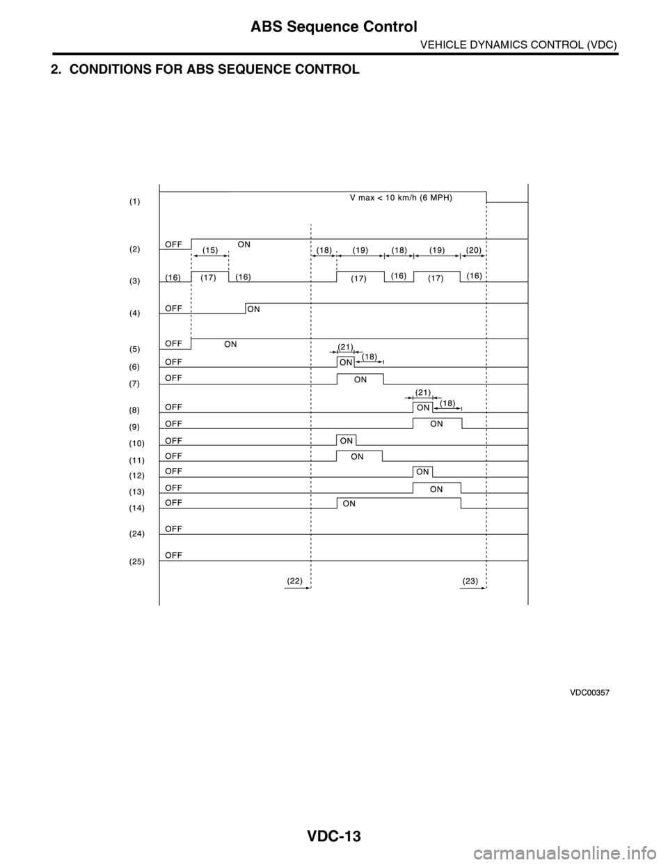
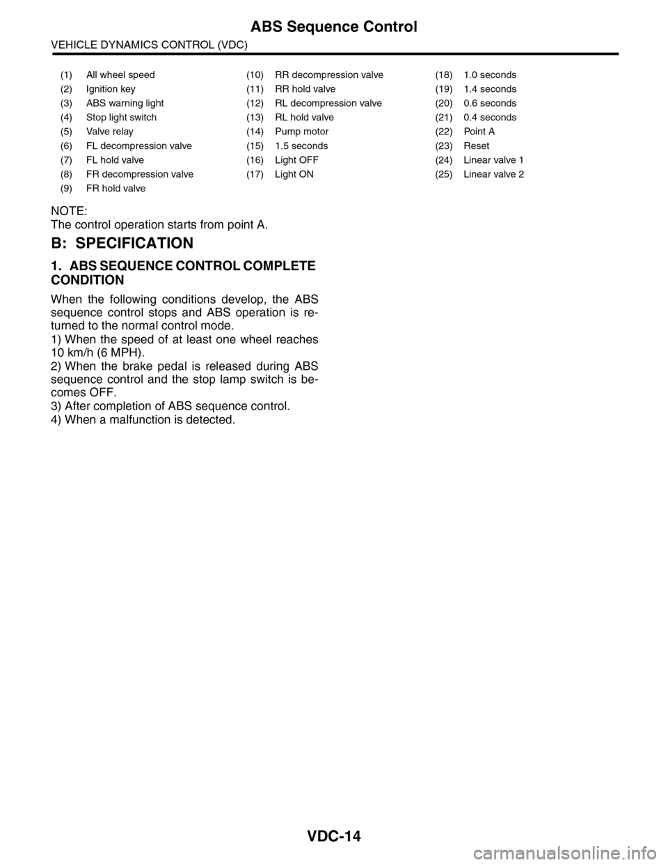
2. CONDITIONS FOR ABS SEQUENCE CONTROL
Page 1095 of 2453
VDC-14
ABS Sequence Control
VEHICLE DYNAMICS CONTROL (VDC)
NOTE:
The control operation starts from point A.
B: SPECIFICATION
1. ABS SEQUENCE CONTROL COMPLETE
CONDITION
When the following conditions develop, the ABS
sequence control stops and ABS operation is re-
turned to the normal control mode.
1) When the speed of at least one wheel reaches
10 km/h (6 MPH).
2) When the brake pedal is released during ABS
sequence control and the stop lamp switch is be-
comes OFF.
3) After completion of ABS sequence control.
4) When a malfunction is detected.
(1) All wheel speed (10) RR decompression valve (18) 1.0 seconds
(2) Ignition key (11) RR hold valve (19) 1.4 seconds
(3) ABS warning light (12) RL decompression valve (20) 0.6 seconds
(4) Stop light switch (13) RL hold valve (21) 0.4 seconds
(5) Valve relay (14) Pump motor (22) Point A
(6) FL decompression valve (15) 1.5 seconds (23) Reset
(7) FL hold valve (16) Light OFF (24) Linear valve 1
(8) FR decompression valve (17) Light ON (25) Linear valve 2
(9) FR hold valve
Page 1096 of 2453
VDC-15
VDC Sequence Control
VEHICLE DYNAMICS CONTROL (VDC)
4. VDC Sequence Control
A: OPERATION
1) While the VDC sequence control is performed,
the operation of the hydraulic unit can be checked
using the brake tester or pressure gauge after the
hydraulic unit solenoid valve is operated.
2) VDC sequence control can be started by Subaru
Select Monitor.
1. VDC SEQUENCE CONTROL WITH SUB-
ARU SELECT MONITOR
NOTE:
In the event of any trouble, sequence control will
not operate.
1) Connect the Subaru Select Monitor to data link
connector under the driver's side instrument panel
lower cover.
2) Turn the ignition switch ON.
3) Set the Subaru Select Monitor switch to ON.
4) Set the Subaru Select Monitor to “Brake Control”
mode.
5) When the “VDC Inspection Mode” is selected
from the “Function check sequence” menu, the
“VDC sequence control” will start.
6) ”Press the “YES” key” will be displayed. Press
the [YES] key.
7) Operation points will be displayed on Subaru Se-
lect Monitor.
Page 1097 of 2453
VDC-16
VDC Sequence Control
VEHICLE DYNAMICS CONTROL (VDC)
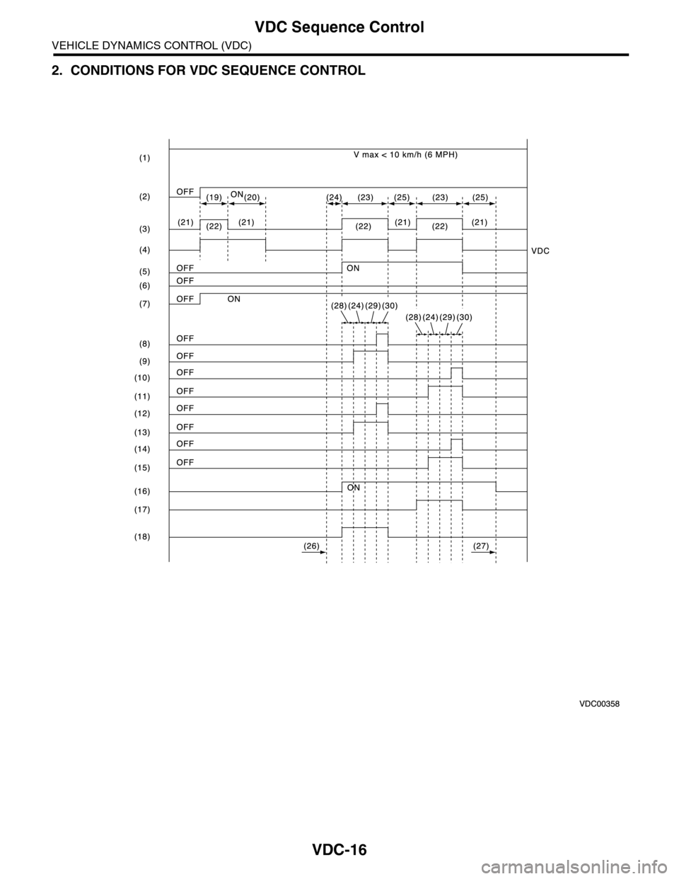
2. CONDITIONS FOR VDC SEQUENCE CONTROL
Page 1098 of 2453
VDC-17
VDC Sequence Control
VEHICLE DYNAMICS CONTROL (VDC)
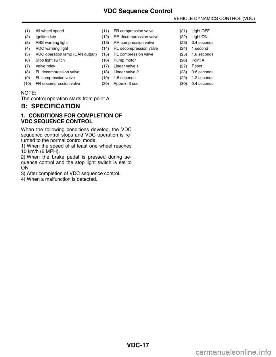
NOTE:
The control operation starts from point A.
B: SPECIFICATION
1. CONDITIONS FOR COMPLETION OF
VDC SEQUENCE CONTROL
When the following conditions develop, the VDC
sequence control stops and VDC operation is re-
turned to the normal control mode.
1) When the speed of at least one wheel reaches
10 km/h (6 MPH).
2) When the brake pedal is pressed during se-
quence control and the stop light switch is set to
ON.
3) After completion of VDC sequence control.
4) When a malfunction is detected.
(1) All wheel speed (11) FR compression valve (21) Light OFF
(2) Ignition key (12) RR decompression valve (22) Light ON
(3) ABS warning light (13) RR compression valve (23) 3.4 seconds
(4) VDC warning light (14) RL decompression valve (24) 1 second
(5) VDC operation lamp (CAN output) (15) RL compression valve (25) 1.6 seconds
(6) Stop light switch (16) Pump motor (26) Point A
(7) Valve relay (17) Linear valve 1 (27) Reset
(8) FL decompression valve (18) Linear valve 2 (28) 0.8 seconds
(9) FL compression valve (19) 1.5 seconds (29) 1.2 seconds
(10) FR decompression valve (20) Approx. 3 sec. (30) 0.4 seconds
Page 1099 of 2453
VDC-18
Yaw Rate & Lateral G Sensor
VEHICLE DYNAMICS CONTROL (VDC)
5. Yaw Rate & Lateral G Sensor
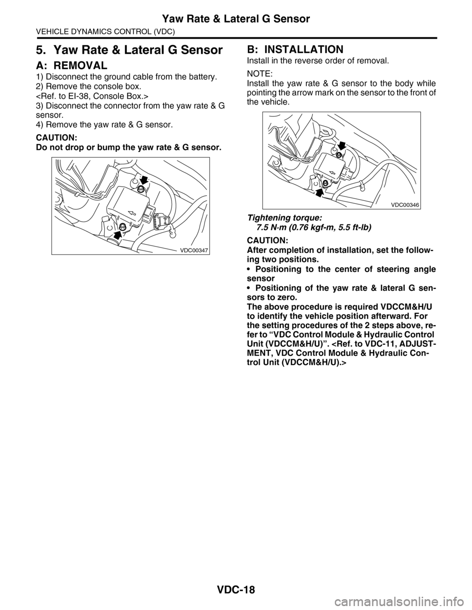
A: REMOVAL
1) Disconnect the ground cable from the battery.
2) Remove the console box.
3) Disconnect the connector from the yaw rate & G
sensor.
4) Remove the yaw rate & G sensor.
CAUTION:
Do not drop or bump the yaw rate & G sensor.
B: INSTALLATION
Install in the reverse order of removal.
NOTE:
Install the yaw rate & G sensor to the body while
pointing the arrow mark on the sensor to the front of
the vehicle.
Tightening torque:
7.5 N·m (0.76 kgf-m, 5.5 ft-lb)
CAUTION:
After completion of installation, set the follow-
ing two positions.
•Positioning to the center of steering angle
sensor
•Positioning of the yaw rate & lateral G sen-
sors to zero.
The above procedure is required VDCCM&H/U
to identify the vehicle position afterward. For
the setting procedures of the 2 steps above, re-
fer to “VDC Control Module & Hydraulic Control
Unit (VDCCM&H/U)”.
trol Unit (VDCCM&H/U).>
VDC00347
VDC00346
Page 1100 of 2453
VDC-19
Steering Angle Sensor
VEHICLE DYNAMICS CONTROL (VDC)
6. Steering Angle Sensor
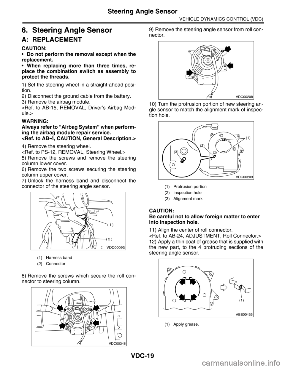
A: REPLACEMENT
CAUTION:
•Do not perform the removal except when the
replacement.
•When replacing more than three times, re-
place the combination switch as assembly to
protect the threads.
1) Set the steering wheel in a straight-ahead posi-
tion.
2) Disconnect the ground cable from the battery.
3) Remove the airbag module.
WARNING:
Always refer to “Airbag System” when perform-
ing the airbag module repair service.
4) Remove the steering wheel.
5) Remove the screws and remove the steering
column lower cover.
6) Remove the two screws securing the steering
column upper cover.
7) Unlock the harness band and disconnect the
connector of the steering angle sensor.
8) Remove the screws which secure the roll con-
nector to steering column.
9) Remove the steering angle sensor from roll con-
nector.
10) Turn the protrusion portion of new steering an-
gle sensor to match the alignment mark of inspec-
tion hole.
CAUTION:
Be careful not to allow foreign matter to enter
into inspection hole.
11) Align the center of roll connector.
12) Apply a thin coat of grease that is supplied with
the new part, to the 4 protruding sections of the
steering angle sensor.
(1) Harness band
(2) Connector
VDC00093
( 1 )
( 2 )
VDC00348
(1) Protrusion portion
(2) Inspection hole
(3) Alignment mark
(1) Apply grease.
VDC00208
VDC00209
(1)
(2)
(3)
ABS00435
(1)