SUBARU TRIBECA 2009 1.G Service Workshop Manual
Manufacturer: SUBARU, Model Year: 2009, Model line: TRIBECA, Model: SUBARU TRIBECA 2009 1.GPages: 2453, PDF Size: 46.32 MB
Page 1081 of 2453
VDC(diag)-89
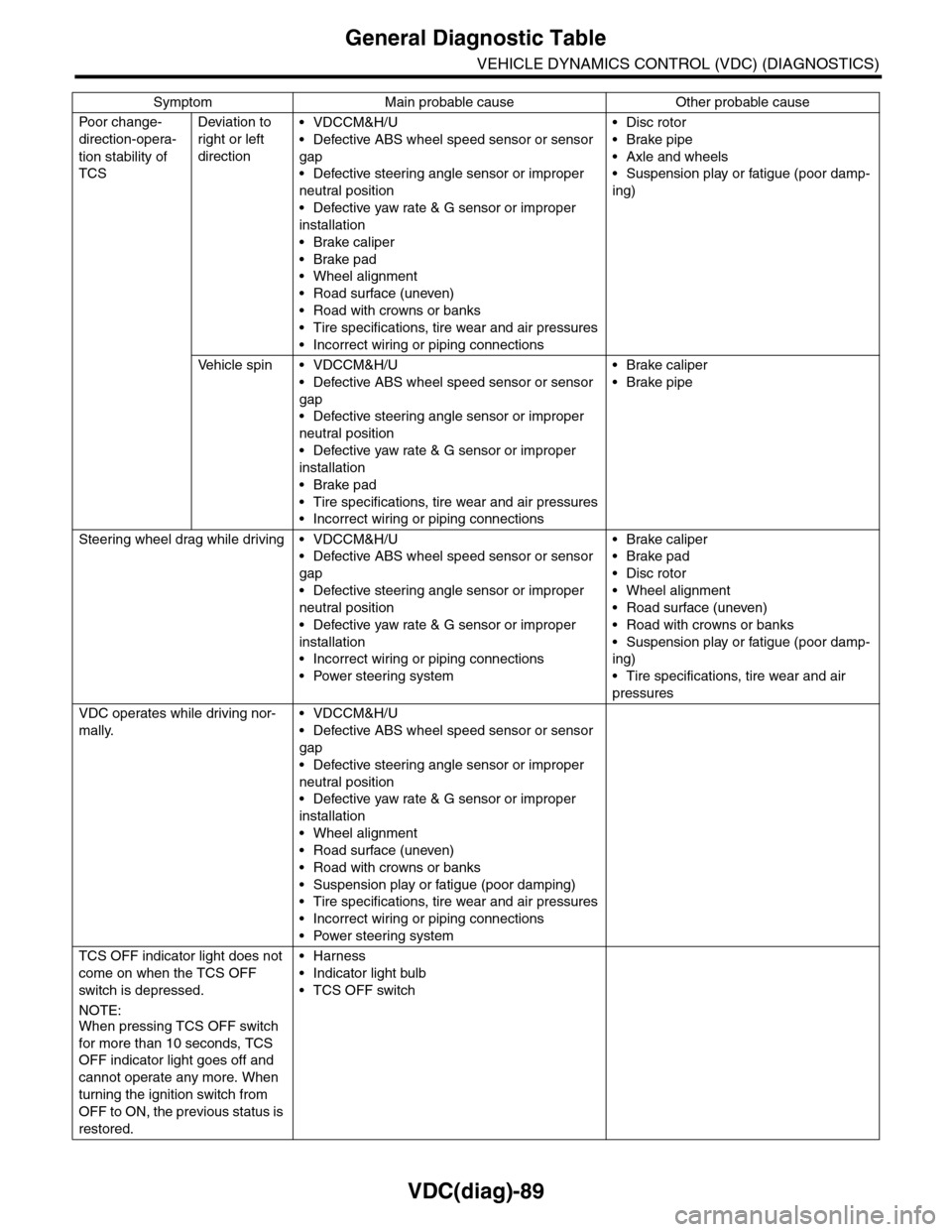
General Diagnostic Table
VEHICLE DYNAMICS CONTROL (VDC) (DIAGNOSTICS)
Po or ch a ng e -
direction-opera-
tion stability of
TCS
Deviation to
right or left
direction
•VDCCM&H/U
•Defective ABS wheel speed sensor or sensor
gap
•Defective steering angle sensor or improper
neutral position
•Defective yaw rate & G sensor or improper
installation
•Brake caliper
•Brake pad
•Wheel alignment
•Road surface (uneven)
•Road with crowns or banks
•Tire specifications, tire wear and air pressures
•Incorrect wiring or piping connections
•Disc rotor
•Brake pipe
•Axle and wheels
•Suspension play or fatigue (poor damp-
ing)
Ve h i c l e s p i n • V D C C M & H / U
•Defective ABS wheel speed sensor or sensor
gap
•Defective steering angle sensor or improper
neutral position
•Defective yaw rate & G sensor or improper
installation
•Brake pad
•Tire specifications, tire wear and air pressures
•Incorrect wiring or piping connections
•Brake caliper
•Brake pipe
Steering wheel drag while driving • VDCCM&H/U
•Defective ABS wheel speed sensor or sensor
gap
•Defective steering angle sensor or improper
neutral position
•Defective yaw rate & G sensor or improper
installation
•Incorrect wiring or piping connections
•Power steering system
•Brake caliper
•Brake pad
•Disc rotor
•Wheel alignment
•Road surface (uneven)
•Road with crowns or banks
•Suspension play or fatigue (poor damp-
ing)
•Tire specifications, tire wear and air
pressures
VDC operates while driving nor-
mally.
•VDCCM&H/U
•Defective ABS wheel speed sensor or sensor
gap
•Defective steering angle sensor or improper
neutral position
•Defective yaw rate & G sensor or improper
installation
•Wheel alignment
•Road surface (uneven)
•Road with crowns or banks
•Suspension play or fatigue (poor damping)
•Tire specifications, tire wear and air pressures
•Incorrect wiring or piping connections
•Power steering system
TCS OFF indicator light does not
come on when the TCS OFF
switch is depressed.
NOTE:When pressing TCS OFF switch
for more than 10 seconds, TCS
OFF indicator light goes off and
cannot operate any more. When
turning the ignition switch from
OFF to ON, the previous status is
restored.
•Harness
•Indicator light bulb
•TCS OFF switch
Symptom Main probable cause Other probable cause
Page 1082 of 2453

VDC(diag)-90
General Diagnostic Table
VEHICLE DYNAMICS CONTROL (VDC) (DIAGNOSTICS)
Page 1083 of 2453
VDC-2
General Description
VEHICLE DYNAMICS CONTROL (VDC)
1. General Description
A: SPECIFICATION
B: COMPONENT
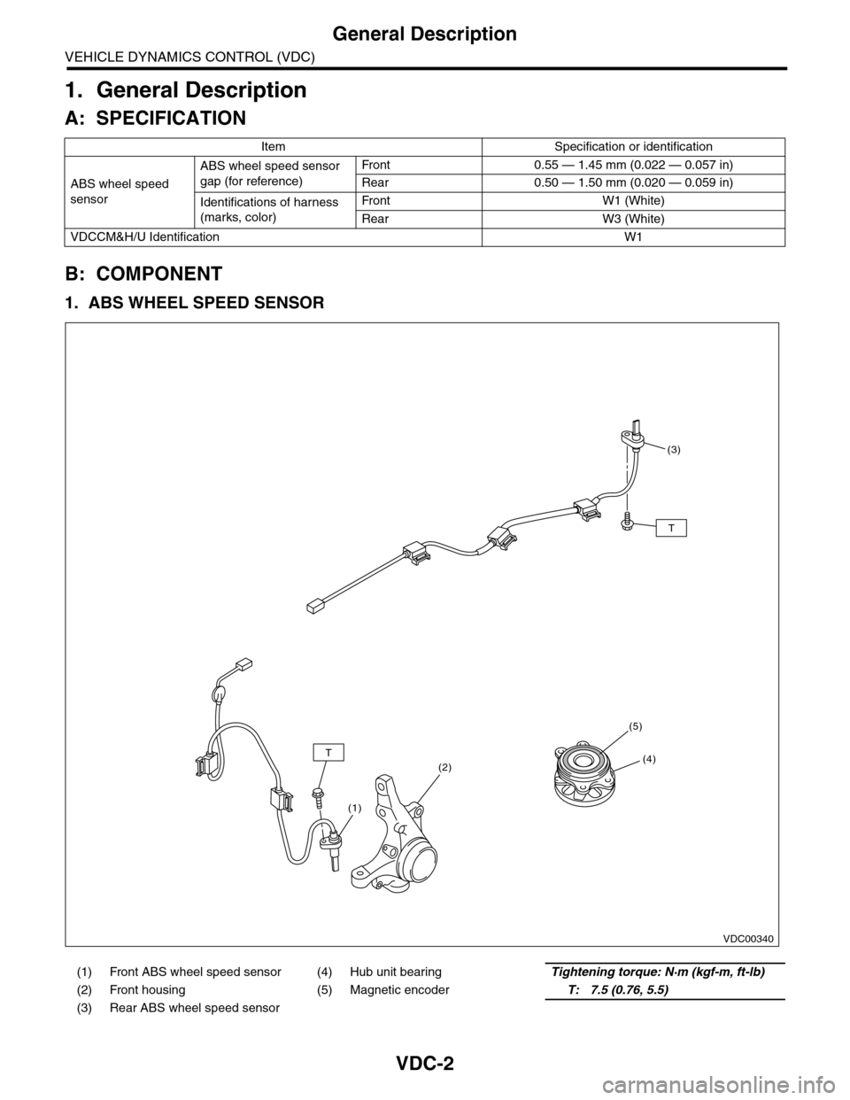
1. ABS WHEEL SPEED SENSOR
Item Specification or identification
ABS wheel speed
sensor
ABS wheel speed sensor
gap (for reference)
Fr o nt 0 . 55 — 1. 4 5 m m ( 0. 0 2 2 — 0. 0 57 i n)
Rear 0.50 — 1.50 mm (0.020 — 0.059 in)
Identifications of harness
(marks, color)
Fr o nt W1 ( Wh i te )
Rear W3 (White)
VDCCM&H/U IdentificationW1
(1) Front ABS wheel speed sensor (4) Hub unit bearingTightening torque: N·m (kgf-m, ft-lb)
(2) Front housing (5) Magnetic encoderT: 7.5 (0.76, 5.5)
(3) Rear ABS wheel speed sensor
VDC00340
T
T
(3)
(4)
(5)
(2)
(1)
Page 1084 of 2453
VDC-3
General Description
VEHICLE DYNAMICS CONTROL (VDC)
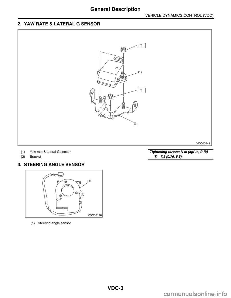
2. YAW RATE & LATERAL G SENSOR
3. STEERING ANGLE SENSOR
(1) Yaw rate & lateral G sensor Tightening torque: N·m (kgf-m, ft-lb)
(2) Bracket T: 7.5 (0.76, 5.5)
VDC00341
(1)
T
T
(2)
(1) Steering angle sensor
VDC00196
(1)
Page 1085 of 2453
VDC-4
General Description
VEHICLE DYNAMICS CONTROL (VDC)
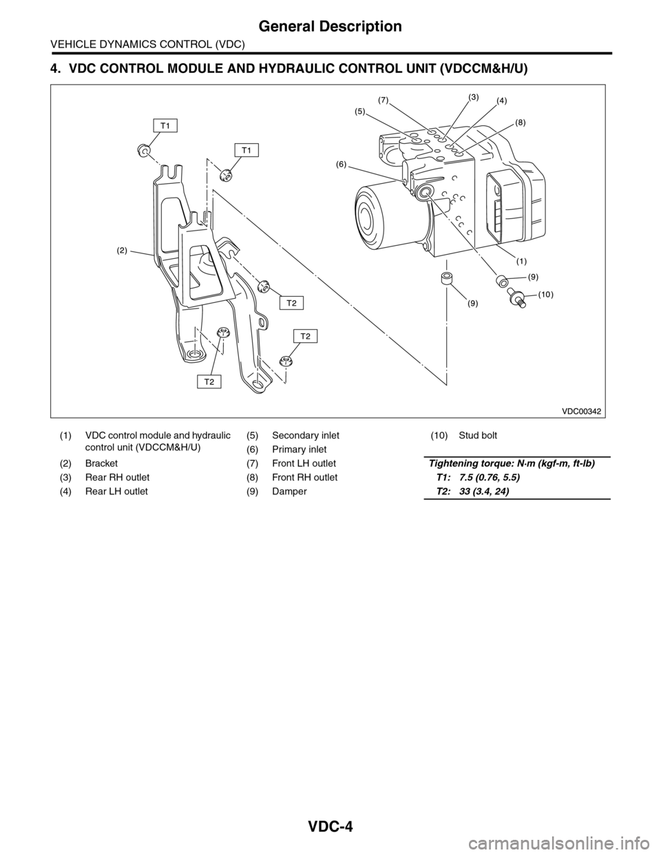
4. VDC CONTROL MODULE AND HYDRAULIC CONTROL UNIT (VDCCM&H/U)
(1) VDC control module and hydraulic
control unit (VDCCM&H/U)
(5) Secondary inlet (10) Stud bolt
(6) Primary inlet
(2) Bracket (7) Front LH outletTightening torque: N·m (kgf-m, ft-lb)
(3) Rear RH outlet (8) Front RH outletT1: 7.5 (0.76, 5.5)
(4) Rear LH outlet (9) DamperT2: 33 (3.4, 24)
Page 1086 of 2453
VDC-5
General Description
VEHICLE DYNAMICS CONTROL (VDC)
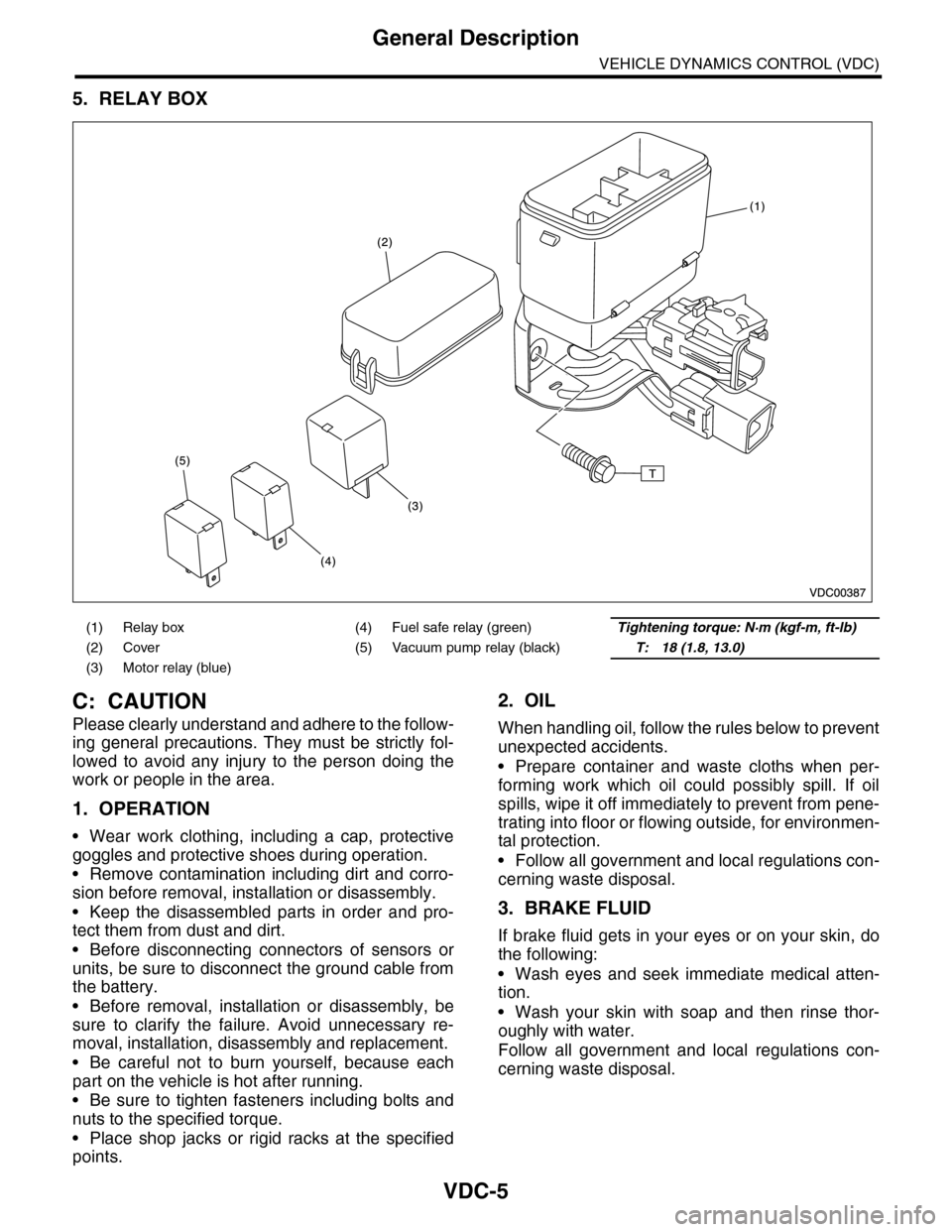
5. RELAY BOX
C: CAUTION
Please clearly understand and adhere to the follow-
ing general precautions. They must be strictly fol-
lowed to avoid any injury to the person doing the
work or people in the area.
1. OPERATION
•Wear work clothing, including a cap, protective
goggles and protective shoes during operation.
•Remove contamination including dirt and corro-
sion before removal, installation or disassembly.
•Keep the disassembled parts in order and pro-
tect them from dust and dirt.
•Before disconnecting connectors of sensors or
units, be sure to disconnect the ground cable from
the battery.
•Before removal, installation or disassembly, be
sure to clarify the failure. Avoid unnecessary re-
moval, installation, disassembly and replacement.
•Be careful not to burn yourself, because each
part on the vehicle is hot after running.
•Be sure to tighten fasteners including bolts and
nuts to the specified torque.
•Place shop jacks or rigid racks at the specified
points.
2. OIL
When handling oil, follow the rules below to prevent
unexpected accidents.
•Prepare container and waste cloths when per-
forming work which oil could possibly spill. If oil
spills, wipe it off immediately to prevent from pene-
trating into floor or flowing outside, for environmen-
tal protection.
•Follow all government and local regulations con-
cerning waste disposal.
3. BRAKE FLUID
If brake fluid gets in your eyes or on your skin, do
the following:
•Wash eyes and seek immediate medical atten-
tion.
•Wash your skin with soap and then rinse thor-
oughly with water.
Follow all government and local regulations con-
cerning waste disposal.
(1) Relay box (4) Fuel safe relay (green)Tightening torque: N·m (kgf-m, ft-lb)
(2) Cover (5) Vacuum pump relay (black)T: 18 (1.8, 13.0)
(3) Motor relay (blue)
Page 1087 of 2453
VDC-6
General Description
VEHICLE DYNAMICS CONTROL (VDC)
D: PREPARATION TOOL
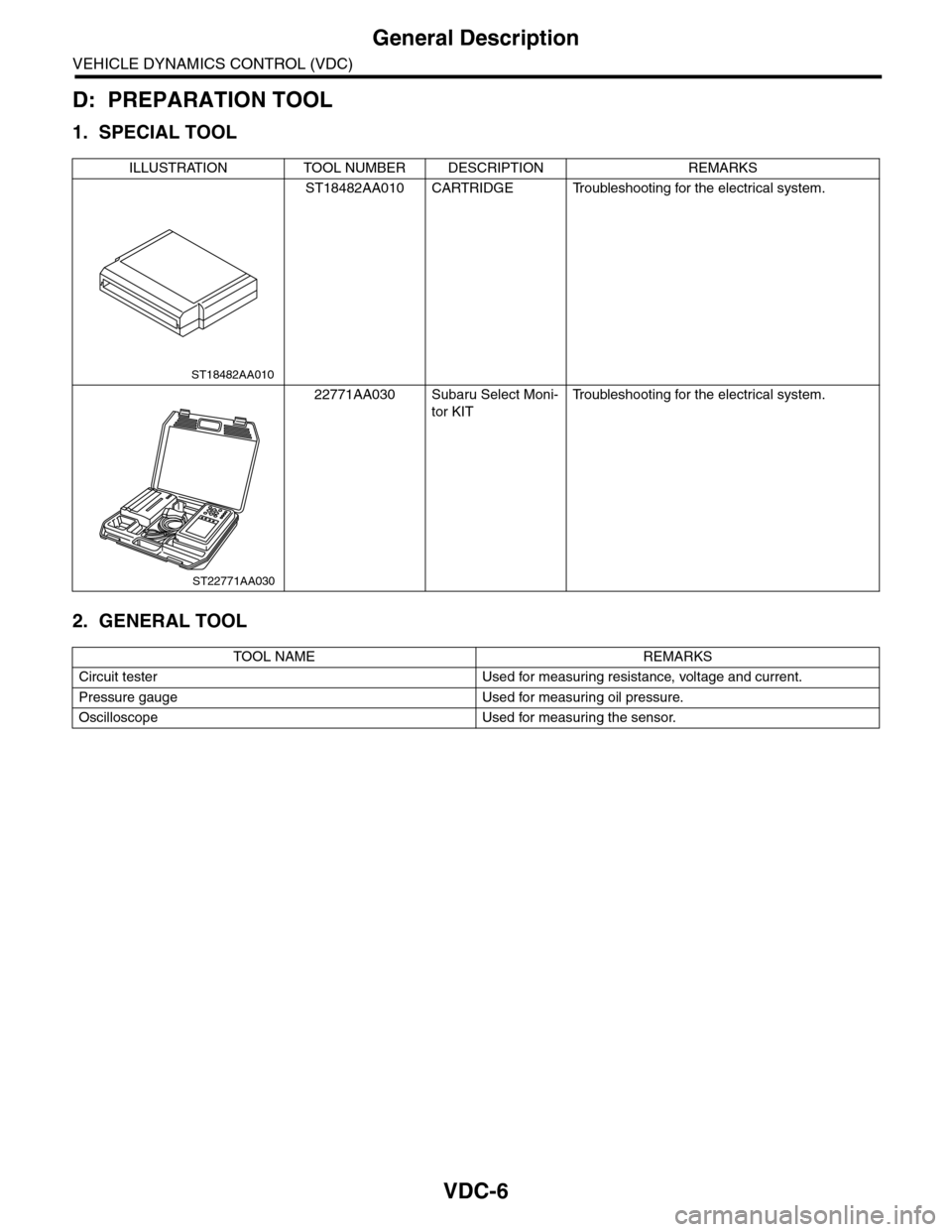
1. SPECIAL TOOL
2. GENERAL TOOL
ILLUSTRATION TOOL NUMBER DESCRIPTION REMARKS
ST18482AA010 CARTRIDGE Troubleshooting for the electrical system.
22771AA030 Subaru Select Moni-
tor KIT
Tr o u b l e s h o o t i n g f o r t h e e l e c t r i c a l s y s t e m .
TOOL NAME REMARKS
Circuit tester Used for measuring resistance, voltage and current.
Pressure gauge Used for measuring oil pressure.
Oscilloscope Used for measuring the sensor.
ST18482AA010
ST22771AA030
Page 1088 of 2453
VDC-7
VDC Control Module & Hydraulic Control Unit (VDCCM&H/U)
VEHICLE DYNAMICS CONTROL (VDC)
2. VDC Control Module & Hy-
draulic Control Unit (VDC-
CM&H/U)
A: REMOVAL
1) Disconnect the ground cable from the battery.
2) Use compressed air to remove moisture and
dust around the VDCCM&H/U.
NOTE:
If the terminals become dirty, it may cause improp-
er contact.
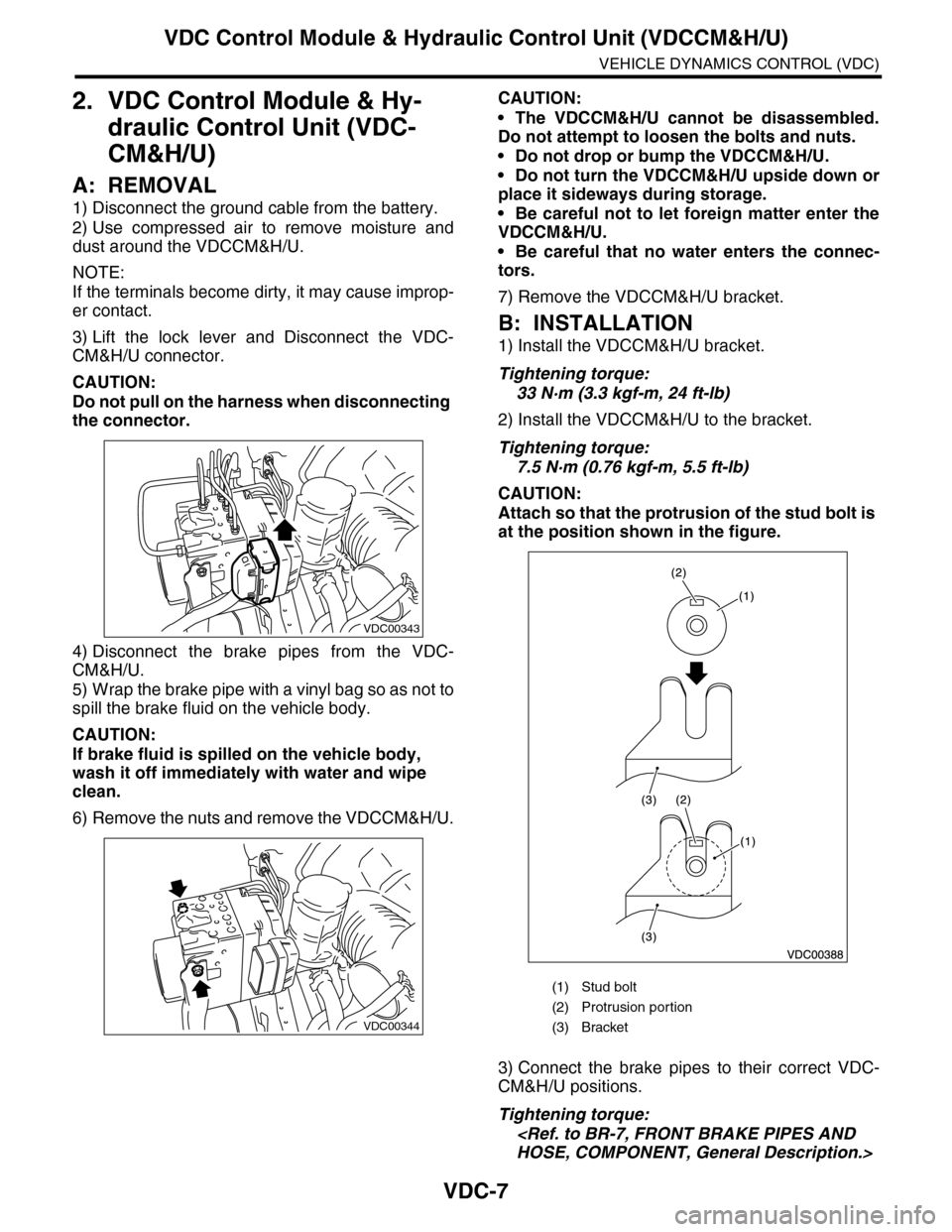
3) Lift the lock lever and Disconnect the VDC-
CM&H/U connector.
CAUTION:
Do not pull on the harness when disconnecting
the connector.
4) Disconnect the brake pipes from the VDC-
CM&H/U.
5) Wrap the brake pipe with a vinyl bag so as not to
spill the brake fluid on the vehicle body.
CAUTION:
If brake fluid is spilled on the vehicle body,
wash it off immediately with water and wipe
clean.
6) Remove the nuts and remove the VDCCM&H/U.
CAUTION:
•The VDCCM&H/U cannot be disassembled.
Do not attempt to loosen the bolts and nuts.
•Do not drop or bump the VDCCM&H/U.
•Do not turn the VDCCM&H/U upside down or
place it sideways during storage.
•Be careful not to let foreign matter enter the
VDCCM&H/U.
•Be careful that no water enters the connec-
tors.
7) Remove the VDCCM&H/U bracket.
B: INSTALLATION
1) Install the VDCCM&H/U bracket.
Tightening torque:
33 N·m (3.3 kgf-m, 24 ft-lb)
2) Install the VDCCM&H/U to the bracket.
Tightening torque:
7.5 N·m (0.76 kgf-m, 5.5 ft-lb)
CAUTION:
Attach so that the protrusion of the stud bolt is
at the position shown in the figure.
3) Connect the brake pipes to their correct VDC-
CM&H/U positions.
Tightening torque:
VDC00343
VDC00344
(1) Stud bolt
(2) Protrusion por tion
(3) Bracket
Page 1089 of 2453
VDC-8
VDC Control Module & Hydraulic Control Unit (VDCCM&H/U)
VEHICLE DYNAMICS CONTROL (VDC)
4) Connect the VDCCM&H/U connectors.
NOTE:
•Be sure to remove all foreign matter from inside
the connector before connecting.
•Make sure the VDCCM&H/U connector is se-
curely locked.
5) Bleed air from the brake system.
C: INSPECTION
1) Check the condition of connection and settle-
ment of connector.
2) Check the mark used for VDCCM&H/U identifi-
cation.
Refer to “SPECIFICATION” for the identification
mark.
1. CHECKING THE HYDRAULIC UNIT ABS
OPERATION BY PRESSURE GAUGE
1) Lift-up the vehicle and remove the wheel.
2) Remove the air bleeder screws from FL and FR
caliper bodies.
3) Connect two pressure gauges to FL and FR cal-
iper bodies.
CAUTION:
•Use a pressure gauge used exclusively for
brake fluid measurement.
•Do not use the pressure gauge used for the
measurement of transmission oil. Doing so will
cause the piston seal to expand and deform.
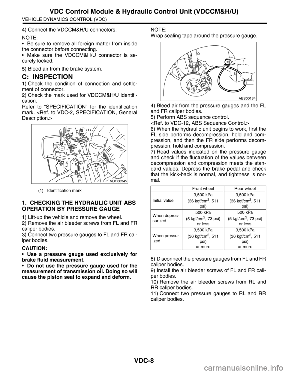
NOTE:
Wrap sealing tape around the pressure gauge.
4) Bleed air from the pressure gauges and the FL
and FR caliper bodies.
5) Perform ABS sequence control.
6) When the hydraulic unit begins to work, first the
FL side performs decompression, hold and com-
pression, and then the FR side performs decom-
pression, hold and compression.
7) Read values indicated on the pressure gauge
and check if the fluctuation of the values between
decompression and compression meets the stan-
dard values. Depress the brake pedal and check
that the kick-back is normal, and tightness is nor-
mal.
8) Disconnect the pressure gauges from FL and FR
caliper bodies.
9) Install the air bleeder screws of FL and FR cali-
per bodies.
10) Remove the air bleeder screws from RL and
RR caliper bodies.
11) Connect two pressure gauges to RL and RR
caliper bodies.
(1) Identification mark
VDC00345
(1)
Front wheelRear wheel
Initial value
3,500 kPa
(36 kgf/cm2, 511
psi)
3,500 kPa
(36 kgf/cm2, 511
psi)
When depres-
surized
500 kPa
(5 kgf/cm2, 73 psi)
or less
500 kPa
(5 kgf/cm2, 73 psi)
or less
When pressur-
ized
3,500 kPa
(36 kgf/cm2, 511
psi)
or more
3,500 kPa
(36 kgf/cm2, 511
psi)
or more
ABS00134
Page 1090 of 2453
VDC-9
VDC Control Module & Hydraulic Control Unit (VDCCM&H/U)
VEHICLE DYNAMICS CONTROL (VDC)
12) Bleed air from the brake system.
13) Bleed air from RL and RR caliper bodies, and
pressure gauge.
14) Perform ABS sequence control.
15) When the hydraulic unit begins to work, first the
RR side performs decompression, hold and com-
pression, and then the RL side performs decom-
pression, hold and compression.
16) Read values indicated on the pressure gauge
and check if the fluctuation of the values between
decompression and compression meets specifica-
tion. Depress the brake pedal and check that the
kick-back is normal, and tightness is normal.
17) Disconnect the pressure gauge from the RL
and RR caliper bodies.
18) Install the air bleeder screws of RL and RR cal-
iper bodies.
19) Bleed air from the brake system.
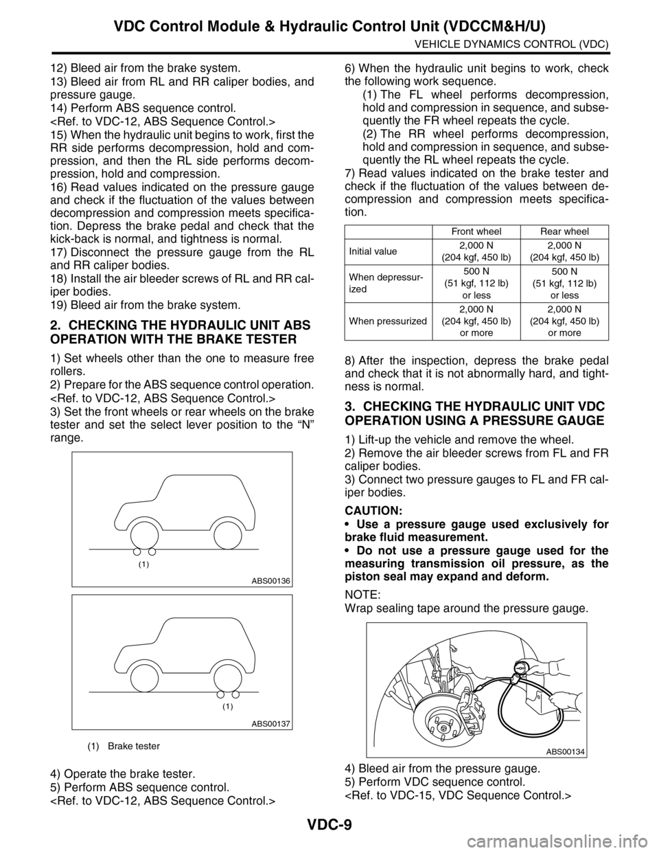
2. CHECKING THE HYDRAULIC UNIT ABS
OPERATION WITH THE BRAKE TESTER
1) Set wheels other than the one to measure free
rollers.
2) Prepare for the ABS sequence control operation.
3) Set the front wheels or rear wheels on the brake
tester and set the select lever position to the “N”
range.
4) Operate the brake tester.
5) Perform ABS sequence control.
6) When the hydraulic unit begins to work, check
the following work sequence.
(1) The FL wheel performs decompression,
hold and compression in sequence, and subse-
quently the FR wheel repeats the cycle.
(2) The RR wheel performs decompression,
hold and compression in sequence, and subse-
quently the RL wheel repeats the cycle.
7) Read values indicated on the brake tester and
check if the fluctuation of the values between de-
compression and compression meets specifica-
tion.
8) After the inspection, depress the brake pedal
and check that it is not abnormally hard, and tight-
ness is normal.
3. CHECKING THE HYDRAULIC UNIT VDC
OPERATION USING A PRESSURE GAUGE
1) Lift-up the vehicle and remove the wheel.
2) Remove the air bleeder screws from FL and FR
caliper bodies.
3) Connect two pressure gauges to FL and FR cal-
iper bodies.
CAUTION:
•Use a pressure gauge used exclusively for
brake fluid measurement.
•Do not use a pressure gauge used for the
measuring transmission oil pressure, as the
piston seal may expand and deform.
NOTE:
Wrap sealing tape around the pressure gauge.
4) Bleed air from the pressure gauge.
5) Perform VDC sequence control.
(1) Brake tester
ABS00136
(1)
ABS00137
(1)
Front wheelRear wheel
Initial value2,000 N
(204 kgf, 450 lb)
2,000 N
(204 kgf, 450 lb)
When depressur-
ized
500 N
(51 kgf, 112 lb)
or less
500 N
(51 kgf, 112 lb)
or less
When pressurized
2,000 N
(204 kgf, 450 lb)
or more
2,000 N
(204 kgf, 450 lb)
or more
ABS00134