SUBARU TRIBECA 2009 1.G Service Workshop Manual
Manufacturer: SUBARU, Model Year: 2009, Model line: TRIBECA, Model: SUBARU TRIBECA 2009 1.GPages: 2453, PDF Size: 46.32 MB
Page 1141 of 2453
CO(H6DO)-22
Radiator Main Fan and Fan Motor
COOLING
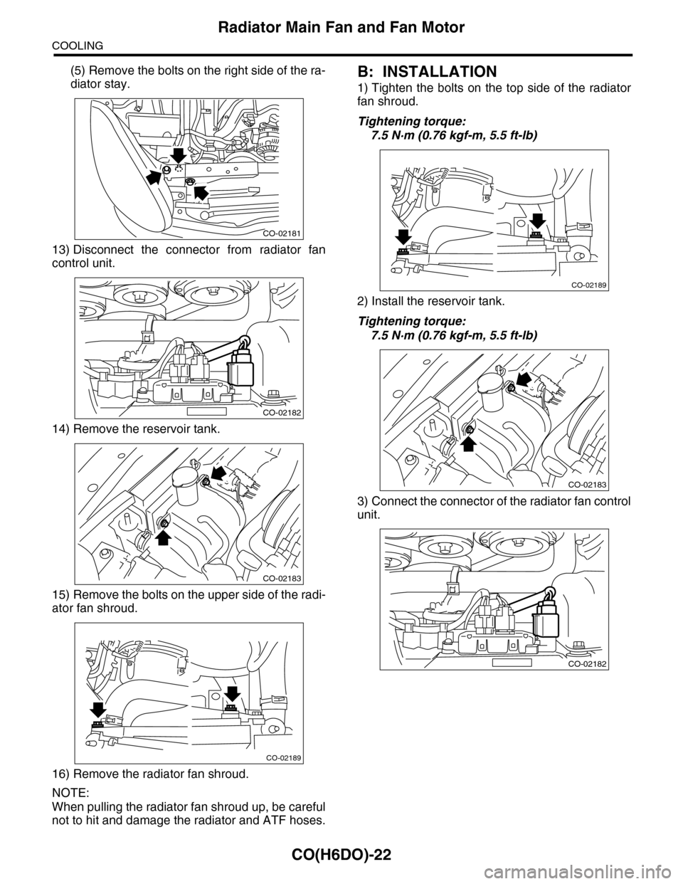
(5) Remove the bolts on the right side of the ra-
diator stay.
13) Disconnect the connector from radiator fan
control unit.
14) Remove the reservoir tank.
15) Remove the bolts on the upper side of the radi-
ator fan shroud.
16) Remove the radiator fan shroud.
NOTE:
When pulling the radiator fan shroud up, be careful
not to hit and damage the radiator and ATF hoses.
B: INSTALLATION
1) Tighten the bolts on the top side of the radiator
fan shroud.
Tightening torque:
7.5 N·m (0.76 kgf-m, 5.5 ft-lb)
2) Install the reservoir tank.
Tightening torque:
7.5 N·m (0.76 kgf-m, 5.5 ft-lb)
3) Connect the connector of the radiator fan control
unit.
CO-02181
CO-02182
CO-02183
CO-02189
CO-02189
CO-02183
CO-02182
Page 1142 of 2453
CO(H6DO)-23
Radiator Main Fan and Fan Motor
COOLING
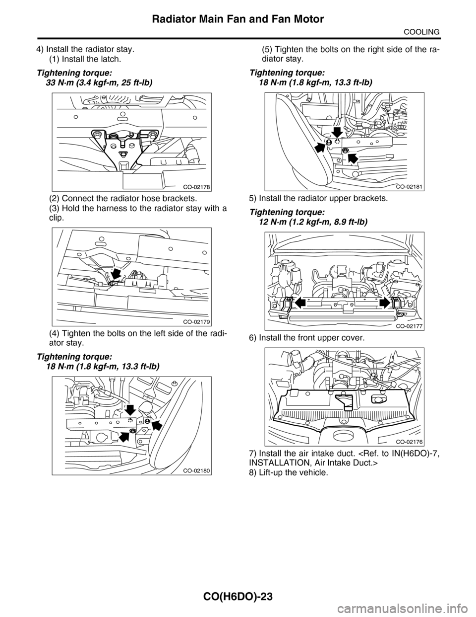
4) Install the radiator stay.
(1) Install the latch.
Tightening torque:
33 N·m (3.4 kgf-m, 25 ft-lb)
(2) Connect the radiator hose brackets.
(3) Hold the harness to the radiator stay with a
clip.
(4) Tighten the bolts on the left side of the radi-
ator stay.
Tightening torque:
18 N·m (1.8 kgf-m, 13.3 ft-lb)
(5) Tighten the bolts on the right side of the ra-
diator stay.
Tightening torque:
18 N·m (1.8 kgf-m, 13.3 ft-lb)
5) Install the radiator upper brackets.
Tightening torque:
12 N·m (1.2 kgf-m, 8.9 ft-lb)
6) Install the front upper cover.
7) Install the air intake duct.
8) Lift-up the vehicle.
CO-02179
CO-02180
CO-02181
CO-02177
CO-02176
Page 1143 of 2453
CO(H6DO)-24
Radiator Main Fan and Fan Motor
COOLING
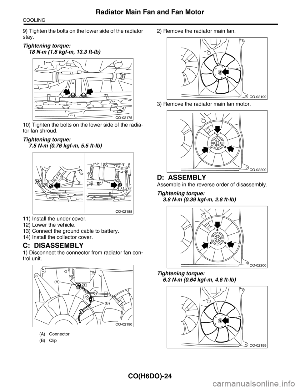
9) Tighten the bolts on the lower side of the radiator
stay.
Tightening torque:
18 N·m (1.8 kgf-m, 13.3 ft-lb)
10) Tighten the bolts on the lower side of the radia-
tor fan shroud.
Tightening torque:
7.5 N·m (0.76 kgf-m, 5.5 ft-lb)
11) Install the under cover.
12) Lower the vehicle.
13) Connect the ground cable to battery.
14) Install the collector cover.
C: DISASSEMBLY
1) Disconnect the connector from radiator fan con-
trol unit.
2) Remove the radiator main fan.
3) Remove the radiator main fan motor.
D: ASSEMBLY
Assemble in the reverse order of disassembly.
Tightening torque:
3.8 N·m (0.39 kgf-m, 2.8 ft-lb)
Tightening torque:
6.3 N·m (0.64 kgf-m, 4.6 ft-lb)
(A) Connector
(B) Clip
CO-02175
CO-02188
CO-02190
(A)
(B)
CO-02199
CO-02200
CO-02200
CO-02199
Page 1144 of 2453
CO(H6DO)-25
Radiator Sub Fan and Fan Motor
COOLING
9. Radiator Sub Fan and Fan
Motor
A: REMOVAL
Refer to the radiator main fan & fan motor.
Fan Motor.>
B: INSTALLATION
Refer to the radiator main fan & fan motor.
Fan and Fan Motor.>
C: DISASSEMBLY
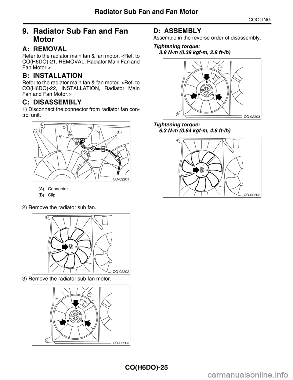
1) Disconnect the connector from radiator fan con-
trol unit.
2) Remove the radiator sub fan.
3) Remove the radiator sub fan motor.
D: ASSEMBLY
Assemble in the reverse order of disassembly.
Tightening torque:
3.8 N·m (0.39 kgf-m, 2.8 ft-lb)
Tightening torque:
6.3 N·m (0.64 kgf-m, 4.6 ft-lb)
(A) Connector
(B) Clip
CO-02201
(A)(B)
CO-02202
CO-02203
CO-02203
CO-02202
Page 1145 of 2453
CO(H6DO)-26
Reservoir Tank
COOLING
10.Reservoir Tank
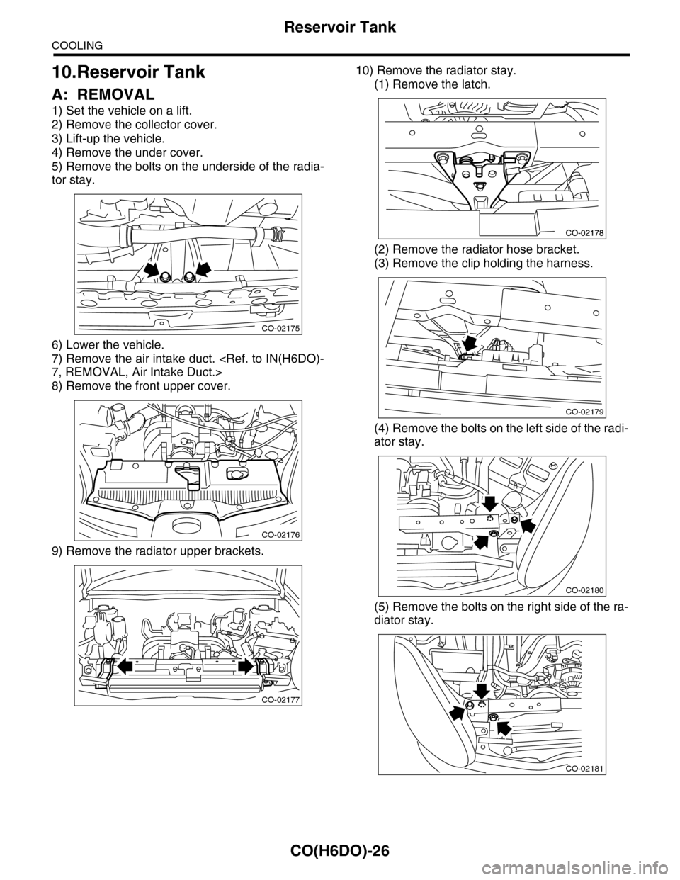
A: REMOVAL
1) Set the vehicle on a lift.
2) Remove the collector cover.
3) Lift-up the vehicle.
4) Remove the under cover.
5) Remove the bolts on the underside of the radia-
tor stay.
6) Lower the vehicle.
7) Remove the air intake duct.
8) Remove the front upper cover.
9) Remove the radiator upper brackets.
10) Remove the radiator stay.
(1) Remove the latch.
(2) Remove the radiator hose bracket.
(3) Remove the clip holding the harness.
(4) Remove the bolts on the left side of the radi-
ator stay.
(5) Remove the bolts on the right side of the ra-
diator stay.
CO-02175
CO-02176
CO-02177
CO-02179
CO-02180
CO-02181
Page 1146 of 2453
CO(H6DO)-27
Reservoir Tank
COOLING
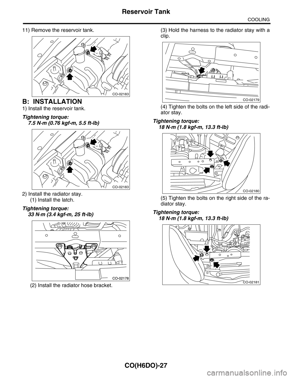
11) Remove the reservoir tank.
B: INSTALLATION
1) Install the reservoir tank.
Tightening torque:
7.5 N·m (0.76 kgf-m, 5.5 ft-lb)
2) Install the radiator stay.
(1) Install the latch.
Tightening torque:
33 N·m (3.4 kgf-m, 25 ft-lb)
(2) Install the radiator hose bracket.
(3) Hold the harness to the radiator stay with a
clip.
(4) Tighten the bolts on the left side of the radi-
ator stay.
Tightening torque:
18 N·m (1.8 kgf-m, 13.3 ft-lb)
(5) Tighten the bolts on the right side of the ra-
diator stay.
Tightening torque:
18 N·m (1.8 kgf-m, 13.3 ft-lb)
CO-02183
CO-02183
CO-02179
CO-02180
CO-02181
Page 1147 of 2453
CO(H6DO)-28
Reservoir Tank
COOLING
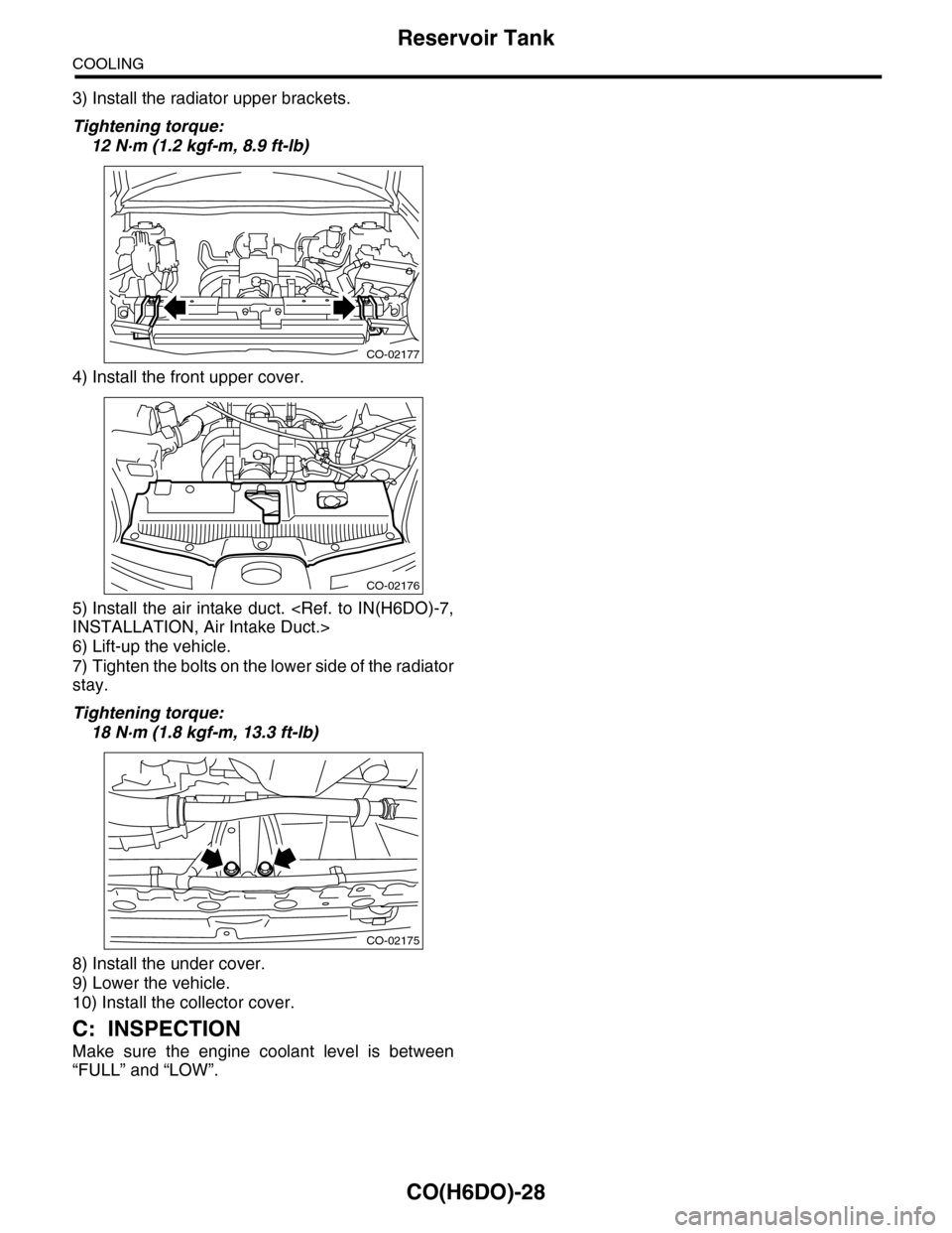
3) Install the radiator upper brackets.
Tightening torque:
12 N·m (1.2 kgf-m, 8.9 ft-lb)
4) Install the front upper cover.
5) Install the air intake duct.
6) Lift-up the vehicle.
7) Tighten the bolts on the lower side of the radiator
stay.
Tightening torque:
18 N·m (1.8 kgf-m, 13.3 ft-lb)
8) Install the under cover.
9) Lower the vehicle.
10) Install the collector cover.
C: INSPECTION
Make sure the engine coolant level is between
“FULL” and “LOW”.
CO-02177
CO-02176
CO-02175
Page 1148 of 2453
CO(H6DO)-29
Radiator Fan Control Unit
COOLING
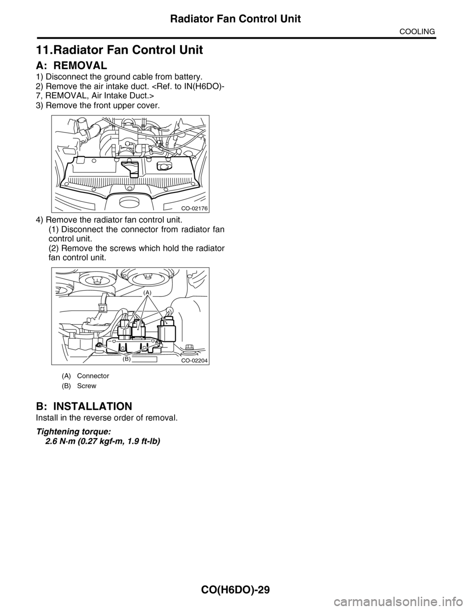
11.Radiator Fan Control Unit
A: REMOVAL
1) Disconnect the ground cable from battery.
2) Remove the air intake duct.
3) Remove the front upper cover.
4) Remove the radiator fan control unit.
(1) Disconnect the connector from radiator fan
control unit.
(2) Remove the screws which hold the radiator
fan control unit.
B: INSTALLATION
Install in the reverse order of removal.
Tightening torque:
2.6 N·m (0.27 kgf-m, 1.9 ft-lb)
(A) Connector
(B) Screw
CO-02176
CO-02204
(A)
(B)
Page 1149 of 2453
CO(H6DO)-30
Engine Cooling System Trouble in General
COOLING
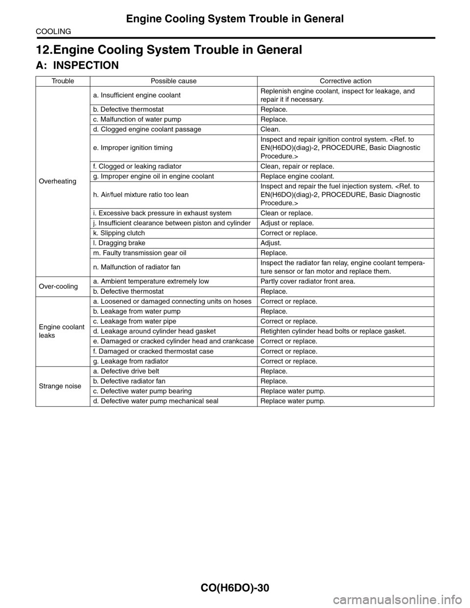
12.Engine Cooling System Trouble in General
A: INSPECTION
Tr o u b l e P o s s i b l e c a u s e C o r r e c t i v e a c t i o n
Overheating
a. Insufficient engine coolantReplenish engine coolant, inspect for leakage, and
repair it if necessary.
b. De fe c ti ve t he r mo st a t Rep la c e.
c. Malfunction of water pump Replace.
d. Clogged engine coolant passage Clean.
e. Improper ignition timing
Inspect and repair ignition control system.
Procedure.>
f. Clogged or leaking radiator Clean, repair or replace.
g. Improper engine oil in engine coolant Replace engine coolant.
h. Air/fuel mixture ratio too lean
Inspect and repair the fuel injection system.
Procedure.>
i. Excessive back pressure in exhaust system Clean or replace.
j. Insufficient clearance between piston and cylinder Adjust or replace.
k. Slipping clutch Correct or replace.
l. Dragging brake Adjust.
m. Faulty transmission gear oil Replace.
n. Malfunction of radiator fanInspect the radiator fan relay, engine coolant tempera-
ture sensor or fan motor and replace them.
Over-coolinga. Ambient temperature extremely low Partly cover radiator front area.
b. De fe c ti ve t he r mo st a t Rep la c e.
Engine coolant
leaks
a. Loosened or damaged connecting units on hoses Correct or replace.
b. L ea k ag e f r o m wat e r pu mp Rep la c e.
c. Leakage from water pipe Correct or replace.
d. Leakage around cylinder head gasket Retighten cylinder head bolts or replace gasket.
e. Damaged or cracked cylinder head and crankcase Correct or replace.
f. Damaged or cracked ther mostat case Correct or replace.
g. Leakage from radiator Correct or replace.
Strange noise
a. Defective drive belt Replace.
b. De fe c ti ve ra di a t or fan Rep la c e.
c. Defective water pump bearing Replace water pump.
d. Defective water pump mechanical seal Replace water pump.
Page 1150 of 2453
EC(H6DO)-2
General Description
EMISSION CONTROL (AUX. EMISSION CONTROL DEVICES)
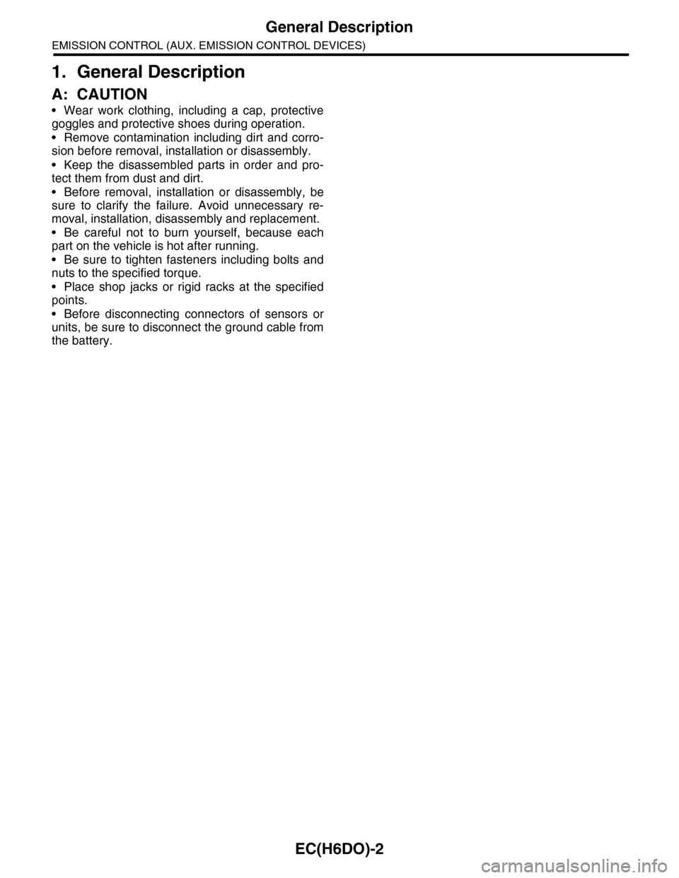
1. General Description
A: CAUTION
•Wear work clothing, including a cap, protective
goggles and protective shoes during operation.
•Remove contamination including dirt and corro-
sion before removal, installation or disassembly.
•Keep the disassembled parts in order and pro-
tect them from dust and dirt.
•Before removal, installation or disassembly, be
sure to clarify the failure. Avoid unnecessary re-
moval, installation, disassembly and replacement.
•Be careful not to burn yourself, because each
part on the vehicle is hot after running.
•Be sure to tighten fasteners including bolts and
nuts to the specified torque.
•Place shop jacks or rigid racks at the specified
points.
•Before disconnecting connectors of sensors or
units, be sure to disconnect the ground cable from
the battery.