SUBARU TRIBECA 2009 1.G Service Workshop Manual
Manufacturer: SUBARU, Model Year: 2009, Model line: TRIBECA, Model: SUBARU TRIBECA 2009 1.GPages: 2453, PDF Size: 46.32 MB
Page 1161 of 2453
EC(H6DO)-13
PCV Valve
EMISSION CONTROL (AUX. EMISSION CONTROL DEVICES)
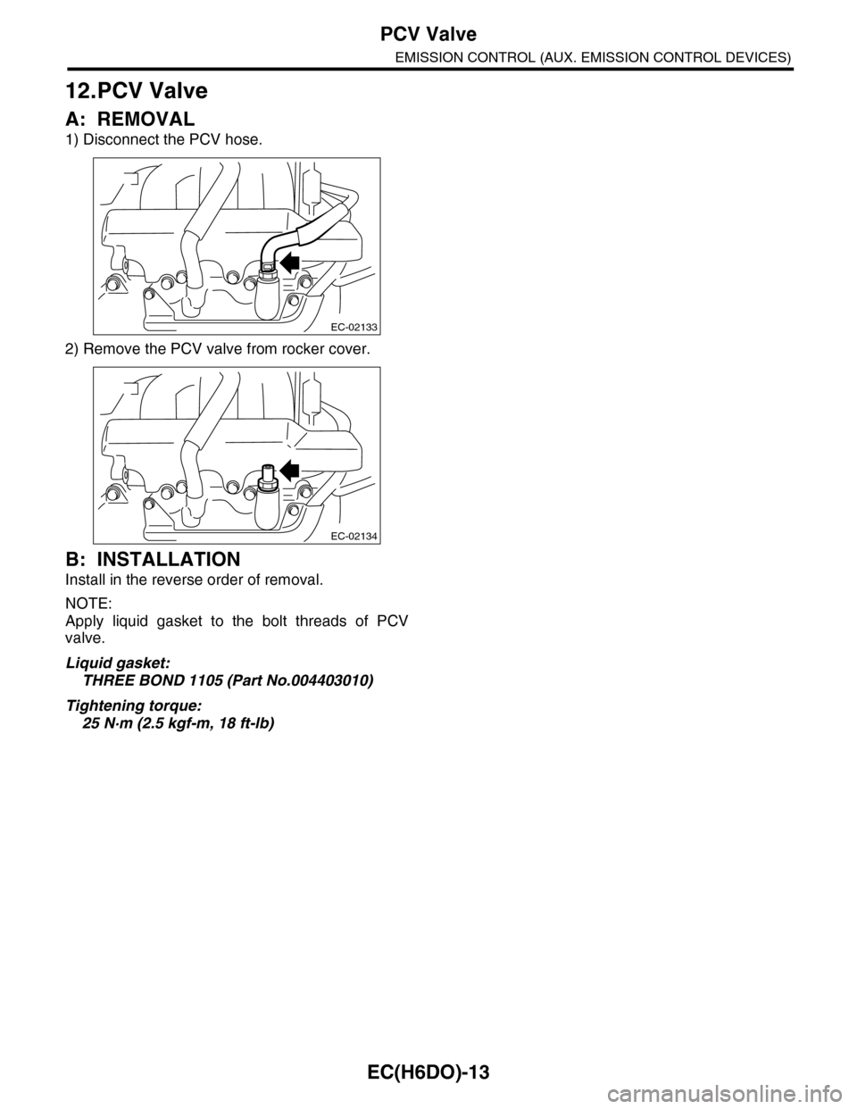
12.PCV Valve
A: REMOVAL
1) Disconnect the PCV hose.
2) Remove the PCV valve from rocker cover.
B: INSTALLATION
Install in the reverse order of removal.
NOTE:
Apply liquid gasket to the bolt threads of PCV
valve.
Liquid gasket:
THREE BOND 1105 (Part No.004403010)
Tightening torque:
25 N·m (2.5 kgf-m, 18 ft-lb)
EC-02133
EC-02134
Page 1162 of 2453
EC(H6DO)-14
PCV Valve
EMISSION CONTROL (AUX. EMISSION CONTROL DEVICES)
Page 1163 of 2453
EN(H6DO)(diag)-2
Basic Diagnostic Procedure
ENGINE (DIAGNOSTICS)
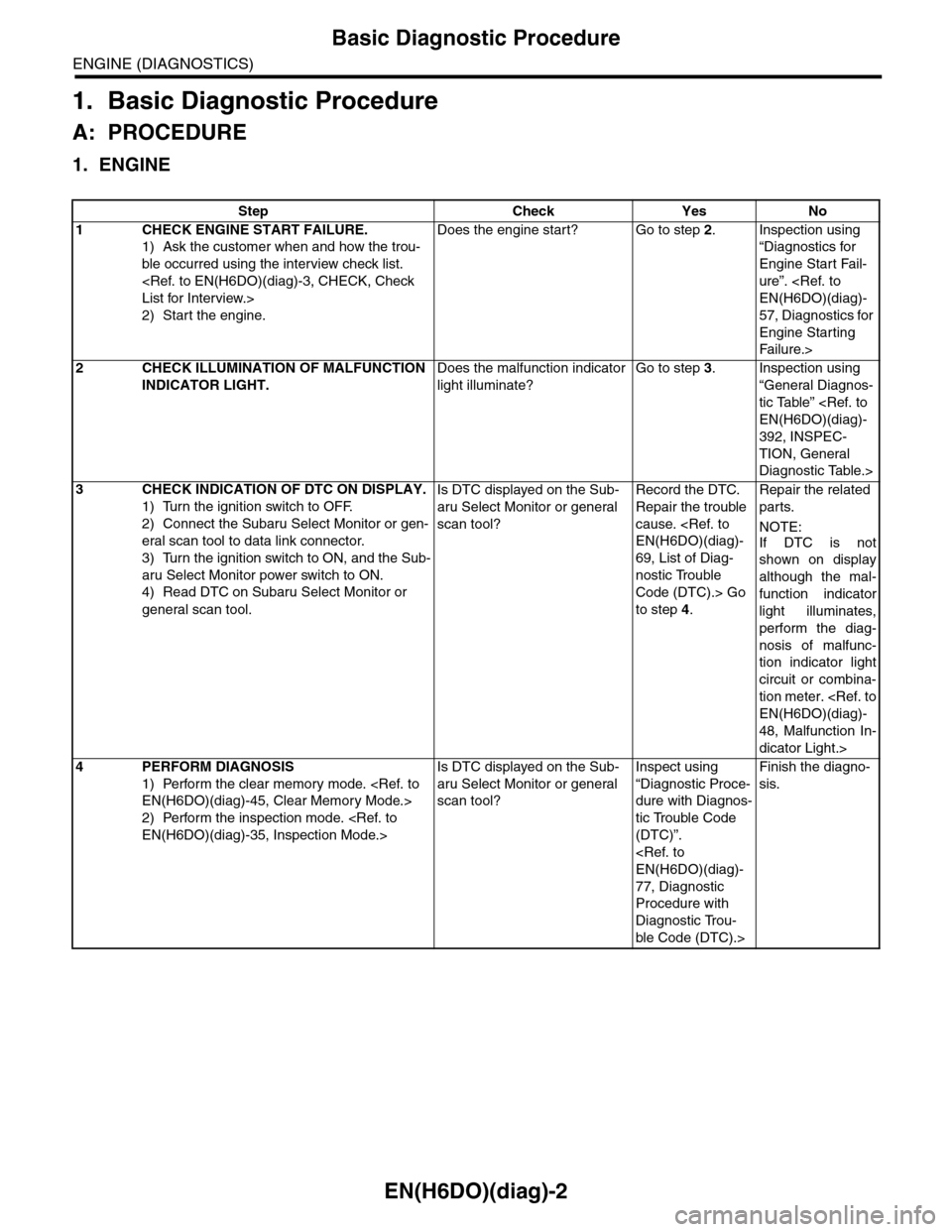
1. Basic Diagnostic Procedure
A: PROCEDURE
1. ENGINE
Step Check Yes No
1CHECK ENGINE START FAILURE.
1) Ask the customer when and how the trou-
ble occurred using the interview check list.
2) Start the engine.
Does the engine start? Go to step 2.Inspection using
“Diagnostics for
Engine Start Fail-
ure”.
57, Diagnostics for
Engine Starting
Fai lu r e.>
2CHECK ILLUMINATION OF MALFUNCTION
INDICATOR LIGHT.
Does the malfunction indicator
light illuminate?
Go to step 3.Inspection using
“General Diagnos-
tic Table”
392, INSPEC-
TION, General
Diagnostic Table.>
3CHECK INDICATION OF DTC ON DISPLAY.
1) Turn the ignition switch to OFF.
2) Connect the Subaru Select Monitor or gen-
eral scan tool to data link connector.
3) Turn the ignition switch to ON, and the Sub-
aru Select Monitor power switch to ON.
4) Read DTC on Subaru Select Monitor or
general scan tool.
Is DTC displayed on the Sub-
aru Select Monitor or general
scan tool?
Record the DTC.
Repair the trouble
cause.
69, List of Diag-
nostic Trouble
Code (DTC).> Go
to step 4.
Repair the related
parts.
NOTE:
If DTC is not
shown on display
although the mal-
function indicator
light illuminates,
perform the diag-
nosis of malfunc-
tion indicator light
circuit or combina-
tion meter.
48, Malfunction In-
dicator Light.>
4PERFORM DIAGNOSIS
1) Perform the clear memory mode.
2) Perform the inspection mode.
Is DTC displayed on the Sub-
aru Select Monitor or general
scan tool?
Inspect using
“Diagnostic Proce-
dure with Diagnos-
tic Trouble Code
(DTC)”.
77, Diagnostic
Procedure with
Diagnostic Trou-
ble Code (DTC).>
Finish the diagno-
sis.
Page 1164 of 2453
EN(H6DO)(diag)-3
Check List for Interview
ENGINE (DIAGNOSTICS)
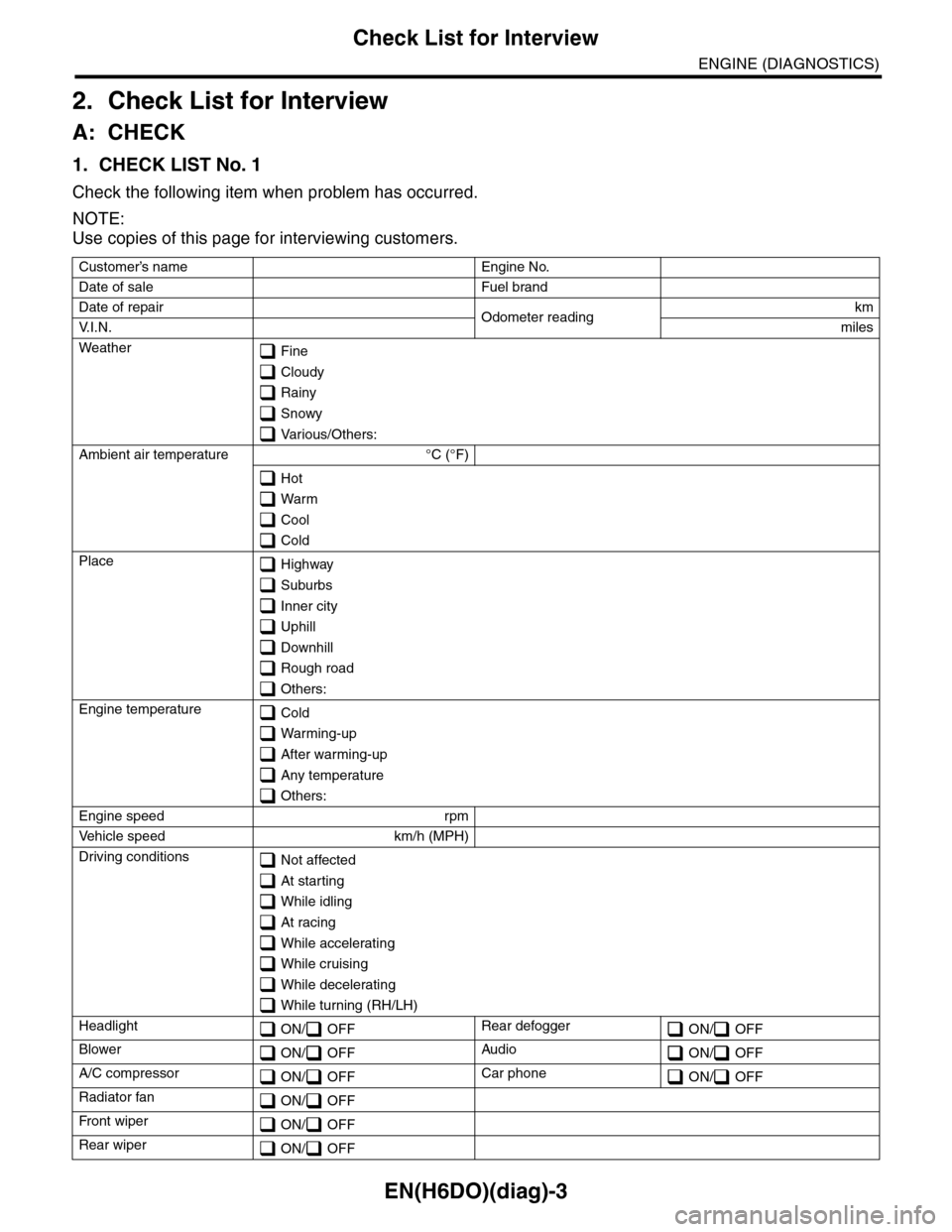
2. Check List for Interview
A: CHECK
1. CHECK LIST No. 1
Check the following item when problem has occurred.
NOTE:
Use copies of this page for interviewing customers.
Customer’s name Engine No.
Date of sale Fuel brand
Date of repair Odometer readingkm
V. I . N . miles
Weather Fine
Cloudy
Rainy
Snowy
Various/Others:
Ambient air temperature °C (°F)
Hot
Warm
Cool
Cold
Place Highway
Suburbs
Inner city
Uphill
Downhill
Rough road
Others:
Engine temperature Cold
Warming-up
After warming-up
Any temperature
Others:
Engine speed rpm
Ve h i c l e s p e e d k m / h ( M P H )
Driving conditions Not affected
At starting
While idling
At racing
While accelerating
While cruising
While decelerating
While turning (RH/LH)
Headlight ON/ OFFRear defogger ON/ OFF
Blower ON/ OFFAudio ON/ OFF
A/C compressor ON/ OFFCar phone ON/ OFF
Radiator fan ON/ OFF
Fr o nt wi pe r ON/ OFF
Rear wiper ON/ OFF
Page 1165 of 2453
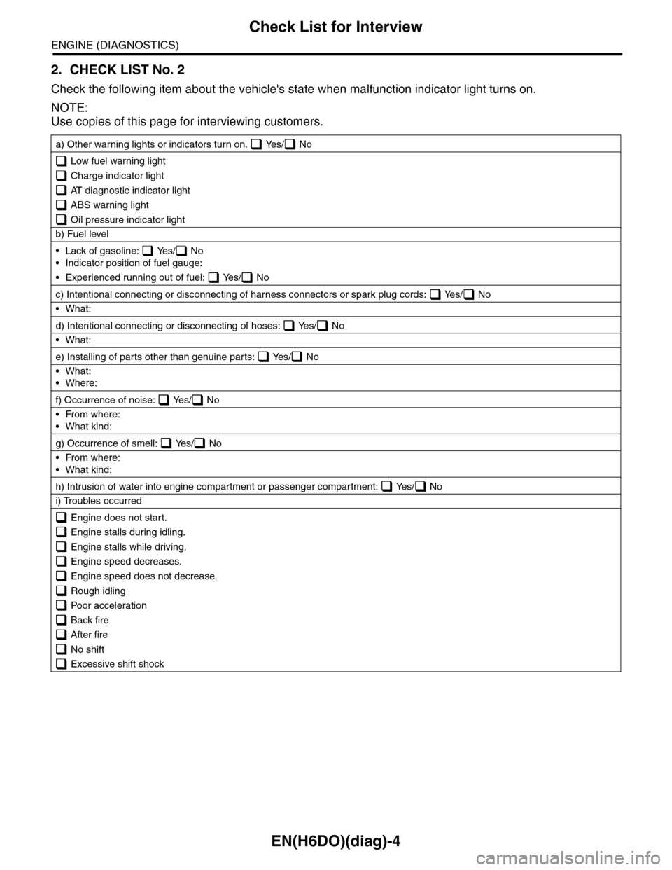
EN(H6DO)(diag)-4
Check List for Interview
ENGINE (DIAGNOSTICS)
2. CHECK LIST No. 2
Check the following item about the vehicle's state when malfunction indicator light turns on.
NOTE:
Use copies of this page for interviewing customers.
a) Other warning lights or indicators turn on. Yes/ No
Low fuel warning light
Charge indicator light
AT diagnostic indicator light
ABS warning light
Oil pressure indicator light
b) Fuel level
•Lack of gasoline: Yes/ No
•Indicator position of fuel gauge:
•Experienced running out of fuel: Yes/ No
c) Intentional connecting or disconnecting of harness connectors or spark plug cords: Yes/ No
•What:
d) Intentional connecting or disconnecting of hoses: Yes/ No
•What:
e) Installing of parts other than genuine parts: Yes/ No
•What:
•Where:
f) Occurrence of noise: Yes/ No
•From where:
•What kind:
g) Occurrence of smell: Yes/ No
•From where:
•What kind:
h) Intrusion of water into engine compartment or passenger compartment: Yes/ No
i) Troubles occurred
Engine does not start.
Engine stalls during idling.
Engine stalls while driving.
Engine speed decreases.
Engine speed does not decrease.
Rough idling
Poor acceleration
Back fire
After fire
No shift
Excessive shift shock
Page 1166 of 2453
EN(H6DO)(diag)-5
General Description
ENGINE (DIAGNOSTICS)
3. General Description
A: CAUTION
1) Airbag system wiring harness is routed near the
ECM, main relay and fuel pump relay.
CAUTION:
•All airbag system wiring harnesses and con-
nectors are colored yellow. Do not use electri-
cal test equipment on these circuits.
•Be careful not to damage the airbag system
wiring harness when servicing the ECM, TCM,
main relay and fuel pump relay.
2) Never connect the battery in reverse polarity.
•The ECM will be destroyed instantly.
•The fuel injector and other parts will be dam-
aged.
3) Do not disconnect the battery terminals while the
engine is running.
A large counter electromotive force will be generat-
ed in the generator, and this voltage may damage
electronic parts such as ECM etc.
4) Before disconnecting the connectors of each
sensor and ECM, be sure to turn the ignition switch
to OFF. Perform the clear memory mode after con-
necting the connectors.
5) Poor contact has been identified as a primary
cause of this problem. Measure the voltage or re-
sistance of individual sensor or all electrical control
modules using a tapered pin with a diameter of less
than 0.64 mm (0.025 in). Do not insert the pin more
than 5 mm (0.20 in) into the part.
6) Remove the ECM from the located position after
disconnecting two cables on battery.
Otherwise, the ECM may be damaged.
CAUTION:
When replacing the ECM, be careful not to use
the wrong spec. ECM to avoid any damage on
the fuel injection system.
7) Connectors of each sensor in the engine com-
partment and the harness connectors on the en-
gine side and body side are all designed to be
waterproof. Even if the connectors are waterproof,
take care not to allow water to get into them when
washing the vehicle, or when servicing the vehicle
in rainy weather.
8) Use ECM mounting stud bolts as the grounding
point to chassis when measuring voltage and resis-
tance in the passenger compartment.
9) Use the engine ground terminal or engine as-
sembly as the grounding point to chassis when
measuring the voltage and resistance in engine
compartment.
10) Every MFI-related part is a precision part. Do
not drop them.
11) Observe the following cautions when installing
a radio in MFI equipped models.
CAUTION:
•The antenna must be kept as far apart as pos-
sible from control unit. (The ECM is located un-
der the steering column, inside of the
instrument panel lower trim panel.)
•The antenna feeder must be placed as far apart
as possible from the ECM and MFI harness.
•Carefully adjust the antenna for correct
matching.
•When mounting a large power type radio, pay
special attention to the three items mentioned
above.
•Incorrect installation of the radio may affect
the operation of ECM.
12) Release the pressure in the fuel system before
disconnecting the fuel hose. If engine starts during
this operation, run it until it stops.
13) For the model with ABS, the ABS warning light
may illuminate when performing driving test with
jacked-up or lifted-up condition, but this is not a
system malfunction. The reason for this is the
speed difference between the front and rear
wheels. After diagnosis of engine control system,
perform the ABS memory clear procedure of self-
diagnosis function.
B: INSPECTION
Before performing diagnostics, check the following
item which might affect engine problems.
1. BATTERY
1) Measure the battery voltage and specific gravity
of electrolyte.
Standard voltage: 12 V
Specific gravity: Above 1.260
2) Check the condition of the main and other fuses,
and harnesses and connectors. Also check for
proper grounding.
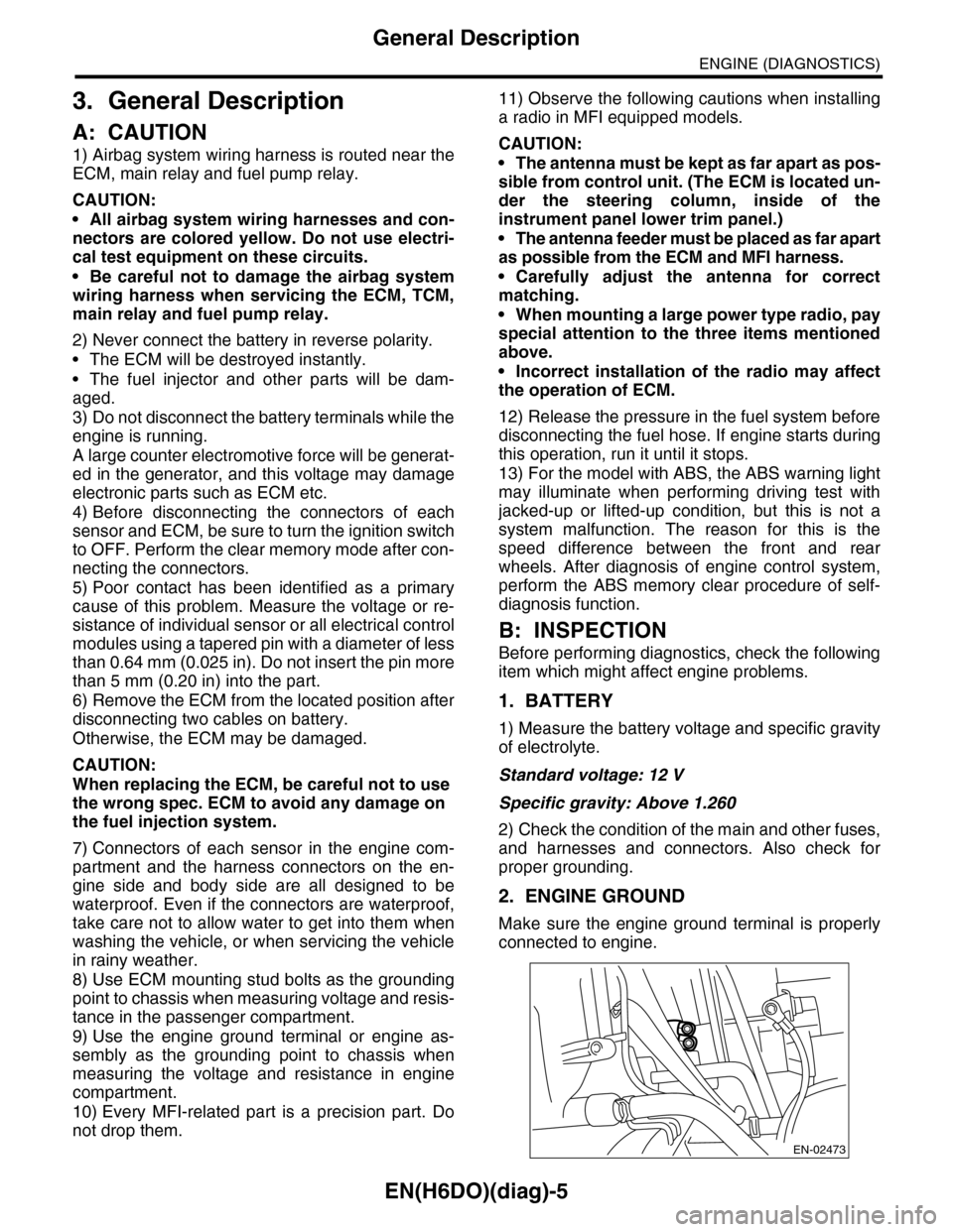
2. ENGINE GROUND
Make sure the engine ground terminal is properly
connected to engine.
EN-02473
Page 1167 of 2453
EN(H6DO)(diag)-6
General Description
ENGINE (DIAGNOSTICS)
C: NOTE
1. GENERAL DESCRIPTION
•The on-board diagnostics (OBD) system detects
and indicates a fault in various inputs and outputs
of the complex electronic control. Malfunction indi-
cator light in the combination meter indicates oc-
currence of a fault or trouble.
•Further, against such a failure or sensors as may
disable the drive, the fail-safe function is provided
to ensure the minimal drivability.
•The OBD system incorporated with the vehicles
within this engine family complies with OBD-II Reg-
ulations. The OBD system monitors the compo-
nents and the system malfunction listed in Engine
Section which affects on emissions.
•When the system decides that a malfunction oc-
curs, malfunction indicator light illuminates. At the
same time of the malfunction indicator light illumi-
nation or blinking, a DTC and a freeze frame en-
gine conditions are stored into on-board computer.
•The OBD system stores freeze frame engine
condition data (engine load, engine coolant tem-
perature, fuel trim, engine speed and vehicle
speed, etc.) into on-board computer when it detects
a malfunction first.
•If the OBD system detects the various malfunc-
tions including the fault of fuel trim or misfire, the
OBD system first stores freeze frame engine condi-
tions about fuel trim or misfire.
•When the malfunction does not occur again for
three consecutive driving cycles, malfunction indi-
cator light is turned off, but DTC remains at on-
board computer.
•When troubleshooting the vehicle which com-
plies with OBD-II Regulations, connect the Subaru
Select Monitor or general scan tool to the vehicle.
2. ENGINE AND EMISSION CONTROL SYS-
TEM
•The Multipoint Fuel Injection (MFI) system is a
system that supplies the optimum air-fuel mixture
to the engine for all the various operating condi-
tions through the use of the latest electronic tech-
nology.
With this system fuel, which is pressurized at a con-
stant pressure, is injected into the intake air pas-
sage of the cylinder head. The injection quantity of
fuel is controlled by an intermittent injection system
where the electro-magnetic injection valve (fuel in-
jector) opens only for a short period of time, de-
pending on the quantity of air required for one cycle
of operation. In actual operation, the injection quan-
tity is determined by the duration of an electric
pulse applied to the fuel injector and this permits
simple, yet highly precise metering of the fuel.
•Further, all the operating conditions of the engine
are converted into electric signals, and this results
in additional features of the system, such as large
improved adaptability, easier addition of compen-
sating element etc.
The MFI system also has the following features:
•Reduced emission of harmful exhaust gases.
•Reduced in fuel consumption.
•Increased engine output.
•Superior acceleration and deceleration.
•Superior startability and warm-up perfor-
mance in cold weather since compensation is
made for coolant and intake air temperature.
Page 1168 of 2453
EN(H6DO)(diag)-7
General Description
ENGINE (DIAGNOSTICS)
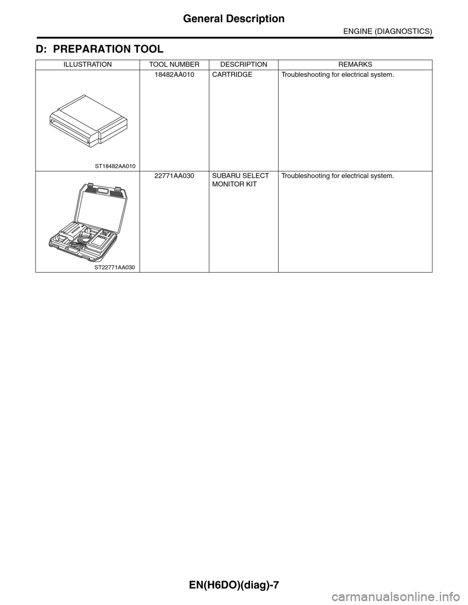
D: PREPARATION TOOL
ILLUSTRATION TOOL NUMBER DESCRIPTION REMARKS
18482AA010 CARTRIDGE Troubleshooting for electrical system.
22771AA030 SUBARU SELECT
MONITOR KIT
Tr o u b l e s h o o t i n g f o r e l e c t r i c a l s y s t e m .
ST18482AA010
ST22771AA030
Page 1169 of 2453
EN(H6DO)(diag)-8
Electrical Component Location
ENGINE (DIAGNOSTICS)
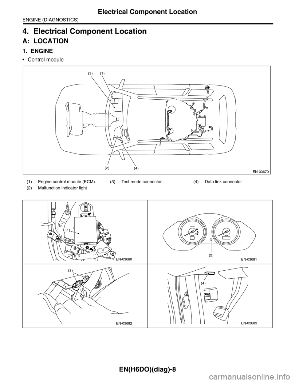
4. Electrical Component Location
A: LOCATION
1. ENGINE
•Control module
(1) Engine control module (ECM) (3) Test mode connector (4) Data link connector
(2) Malfunction indicator light
EN-03679
(1)
(4)
(3)
(2)
EN-03680
(1)
EN-03681
CHECKENGINE
(2)
x1000/min
EN-03682
(3)
EN-03683
(4)
Page 1170 of 2453
EN(H6DO)(diag)-9
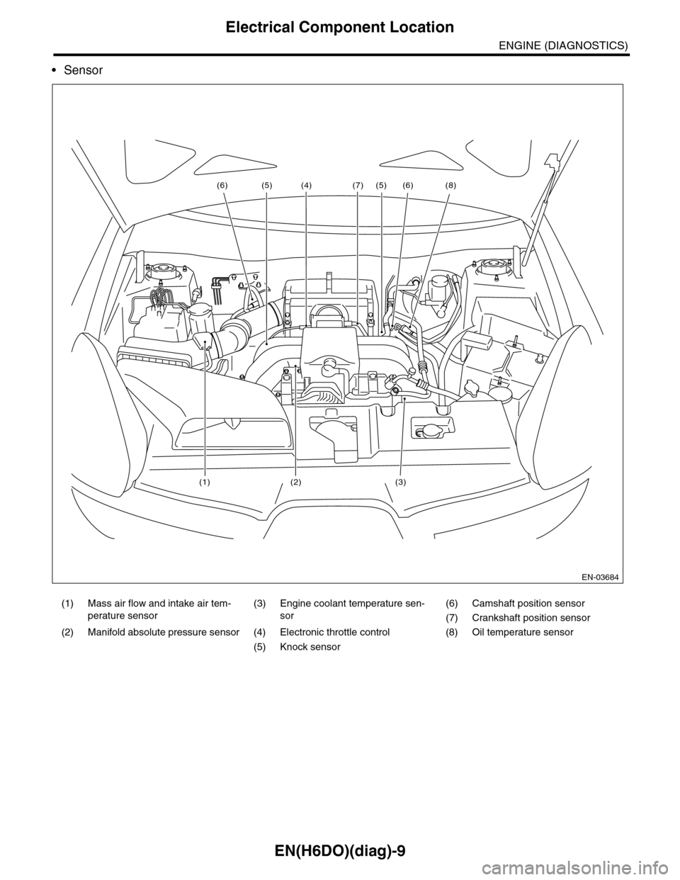
Electrical Component Location
ENGINE (DIAGNOSTICS)
•Sensor
(1) Mass air flow and intake air tem-
perature sensor
(3) Engine coolant temperature sen-
sor
(6) Camshaft position sensor
(7) Crankshaft position sensor
(2) Manifold absolute pressure sensor (4) Electronic throttle control (8) Oil temperature sensor
(5) Knock sensor
EN-03684
(6)(6) (8)
(3)(2)
(7)
(1)
(4) (5)(5)