SUBARU TRIBECA 2009 1.G Service Workshop Manual
TRIBECA 2009 1.G
SUBARU
SUBARU
https://www.carmanualsonline.info/img/17/7322/w960_7322-0.png
SUBARU TRIBECA 2009 1.G Service Workshop Manual
Trending: air cleaner, Belt, bulb, R60, cooling, door, obd
Page 1151 of 2453
EC(H6DO)-3
Front Catalytic Converter
EMISSION CONTROL (AUX. EMISSION CONTROL DEVICES)
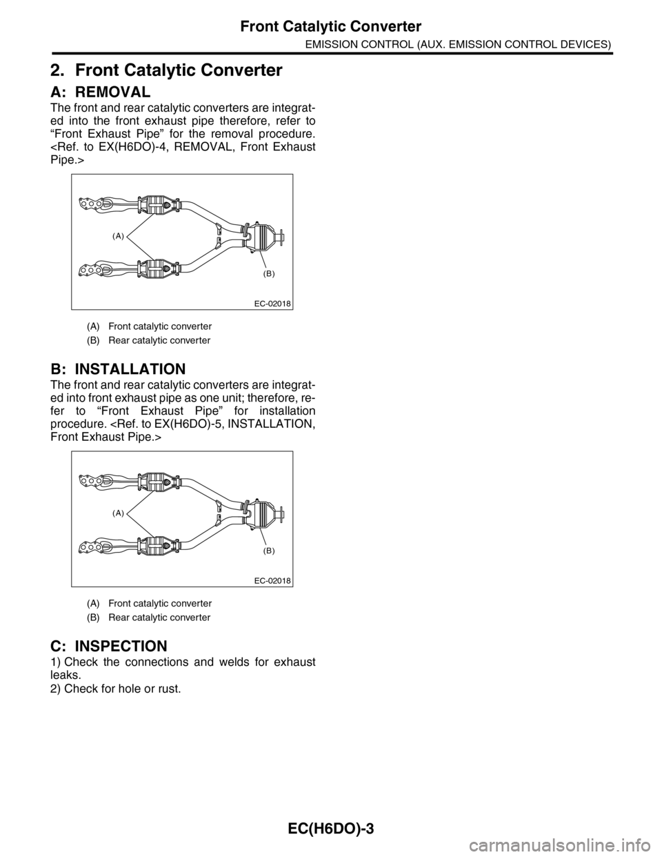
2. Front Catalytic Converter
A: REMOVAL
The front and rear catalytic converters are integrat-
ed into the front exhaust pipe therefore, refer to
“Front Exhaust Pipe” for the removal procedure.
Pipe.>
B: INSTALLATION
The front and rear catalytic converters are integrat-
ed into front exhaust pipe as one unit; therefore, re-
fer to “Front Exhaust Pipe” for installation
procedure.
Front Exhaust Pipe.>
C: INSPECTION
1) Check the connections and welds for exhaust
leaks.
2) Check for hole or rust.
(A) Front catalytic converter
(B) Rear catalytic converter
(A) Front catalytic converter
(B) Rear catalytic converter
(A)
(B)
EC-02018
(A)
(B)
EC-02018
Page 1152 of 2453
EC(H6DO)-4
Rear Catalytic Converter
EMISSION CONTROL (AUX. EMISSION CONTROL DEVICES)
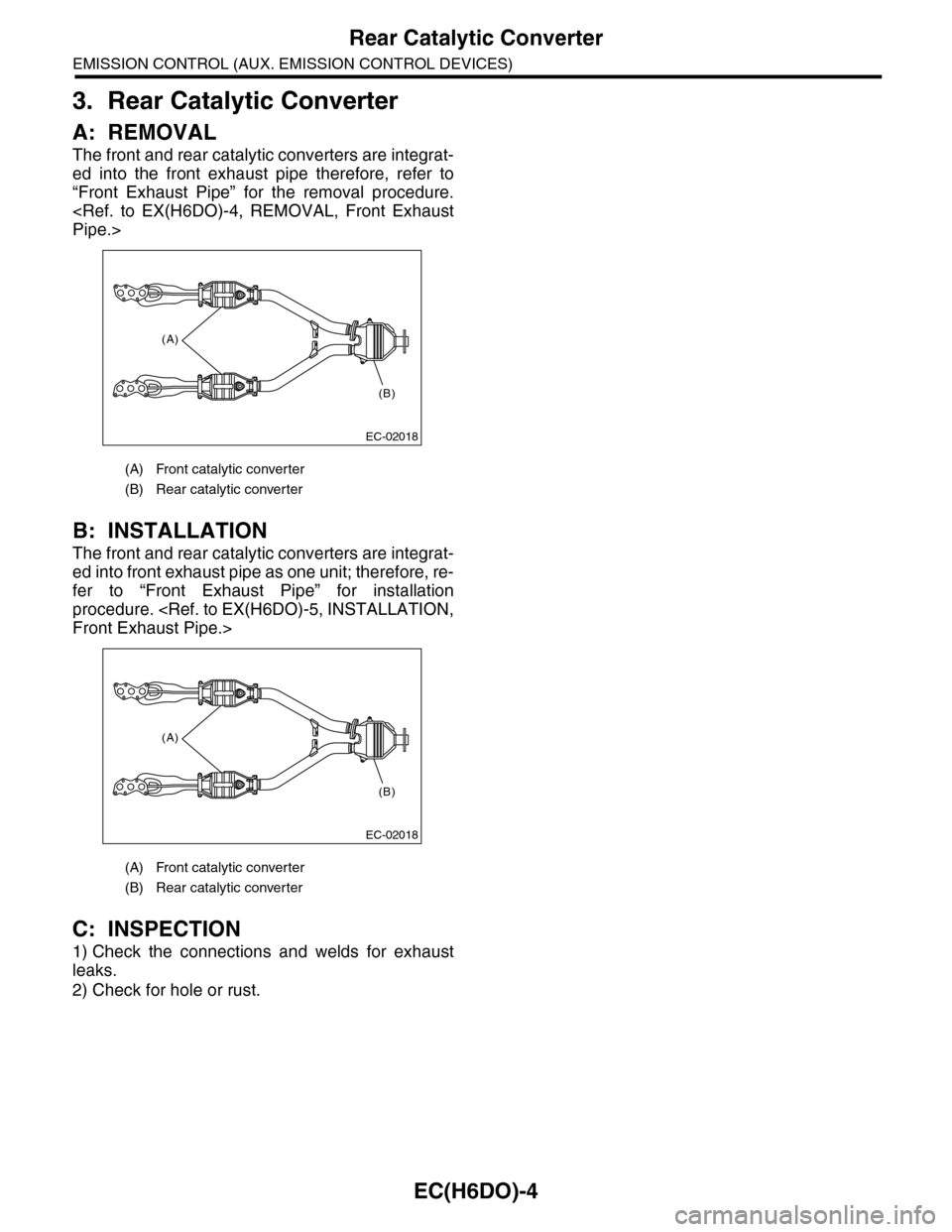
3. Rear Catalytic Converter
A: REMOVAL
The front and rear catalytic converters are integrat-
ed into the front exhaust pipe therefore, refer to
“Front Exhaust Pipe” for the removal procedure.
Pipe.>
B: INSTALLATION
The front and rear catalytic converters are integrat-
ed into front exhaust pipe as one unit; therefore, re-
fer to “Front Exhaust Pipe” for installation
procedure.
Front Exhaust Pipe.>
C: INSPECTION
1) Check the connections and welds for exhaust
leaks.
2) Check for hole or rust.
(A) Front catalytic converter
(B) Rear catalytic converter
(A) Front catalytic converter
(B) Rear catalytic converter
(A)
(B)
EC-02018
(A)
(B)
EC-02018
Page 1153 of 2453
EC(H6DO)-5
Canister
EMISSION CONTROL (AUX. EMISSION CONTROL DEVICES)
4. Canister
A: REMOVAL
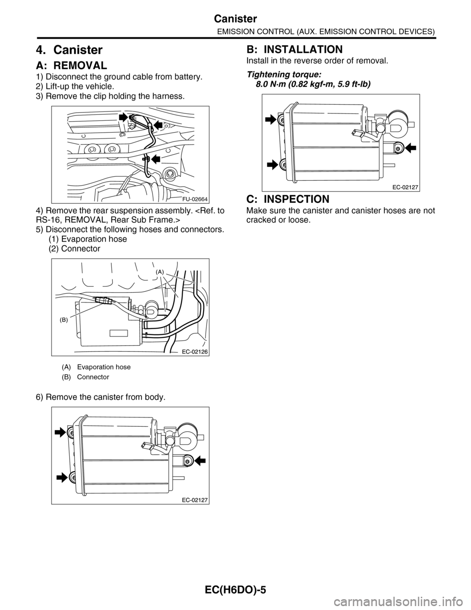
1) Disconnect the ground cable from battery.
2) Lift-up the vehicle.
3) Remove the clip holding the harness.
4) Remove the rear suspension assembly.
RS-16, REMOVAL, Rear Sub Frame.>
5) Disconnect the following hoses and connectors.
(1) Evaporation hose
(2) Connector
6) Remove the canister from body.
B: INSTALLATION
Install in the reverse order of removal.
Tightening torque:
8.0 N·m (0.82 kgf-m, 5.9 ft-lb)
C: INSPECTION
Make sure the canister and canister hoses are not
cracked or loose.
(A) Evaporation hose
(B) Connector
FU-02664
Page 1154 of 2453
EC(H6DO)-6
Purge Control Solenoid Valve
EMISSION CONTROL (AUX. EMISSION CONTROL DEVICES)
5. Purge Control Solenoid Valve
A: REMOVAL
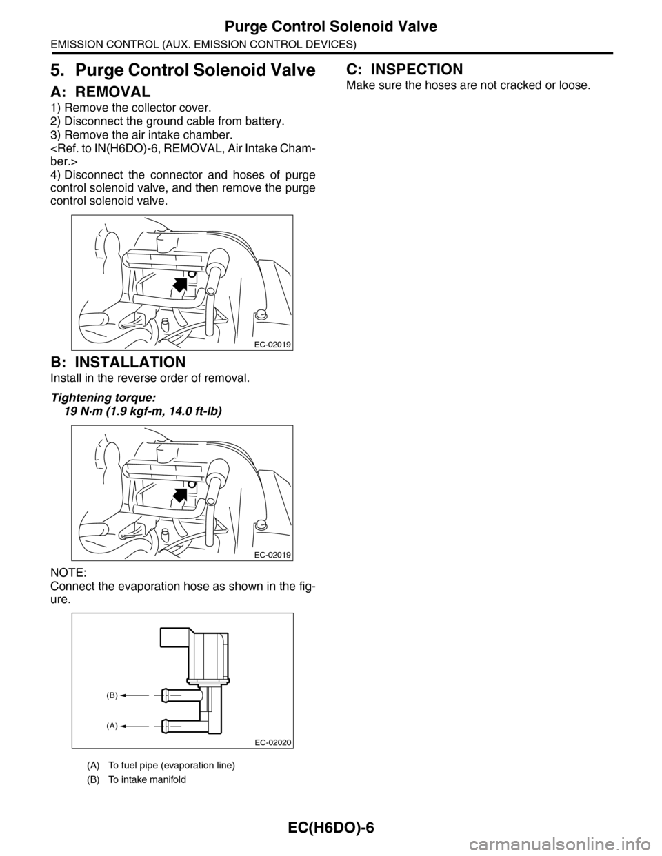
1) Remove the collector cover.
2) Disconnect the ground cable from battery.
3) Remove the air intake chamber.
ber.>
4) Disconnect the connector and hoses of purge
control solenoid valve, and then remove the purge
control solenoid valve.
B: INSTALLATION
Install in the reverse order of removal.
Tightening torque:
19 N·m (1.9 kgf-m, 14.0 ft-lb)
NOTE:
Connect the evaporation hose as shown in the fig-
ure.
C: INSPECTION
Make sure the hoses are not cracked or loose.
(A) To fuel pipe (evaporation line)
(B) To intake manifold
EC-02019
EC-02019
EC-02020
(B)
(A)
Page 1155 of 2453
EC(H6DO)-7
Fuel Level Sensor
EMISSION CONTROL (AUX. EMISSION CONTROL DEVICES)
6. Fuel Level Sensor
A: REMOVAL
For removal procedure, refer to “FU(H6DO)” sec-
tion.
el Sensor.>
B: INSTALLATION
For installation procedure, refer to “FU(H6DO)”
section.
Fuel Level Sensor.>
Page 1156 of 2453
EC(H6DO)-8
Fuel Temperature Sensor
EMISSION CONTROL (AUX. EMISSION CONTROL DEVICES)
7. Fuel Temperature Sensor
A: REMOVAL
The fuel temperature sensor and fuel level sensor
are integrated into one unit; therefore, refer to “Fuel
Level Sensor” for removal procedure.
FU(H6DO)-45, REMOVAL, Fuel Level Sensor.>
B: INSTALLATION
The fuel temperature sensor and fuel level sensor
are integrated into one unit; therefore, refer to “Fuel
Level Sensor” for installation procedure.
FU(H6DO)-45, INSTALLATION, Fuel Level Sen-
sor.>
Page 1157 of 2453
EC(H6DO)-9
Fuel Sub Level Sensor
EMISSION CONTROL (AUX. EMISSION CONTROL DEVICES)
8. Fuel Sub Level Sensor
A: REMOVAL
For removal procedure, refer to “FU(H6DO)” sec-
tion.
Level Sensor.>
B: INSTALLATION
For installation procedure, refer to “FU(H6DO)”
section.
Fuel Sub Level Sensor.>
Page 1158 of 2453
EC(H6DO)-10
Fuel Tank Pressure Sensor
EMISSION CONTROL (AUX. EMISSION CONTROL DEVICES)
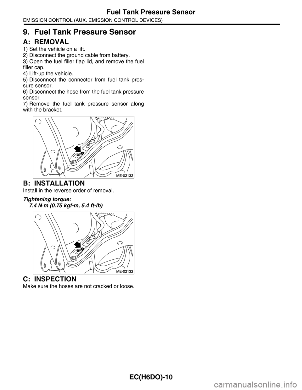
9. Fuel Tank Pressure Sensor
A: REMOVAL
1) Set the vehicle on a lift.
2) Disconnect the ground cable from battery.
3) Open the fuel filler flap lid, and remove the fuel
filler cap.
4) Lift-up the vehicle.
5) Disconnect the connector from fuel tank pres-
sure sensor.
6) Disconnect the hose from the fuel tank pressure
sensor.
7) Remove the fuel tank pressure sensor along
with the bracket.
B: INSTALLATION
Install in the reverse order of removal.
Tightening torque:
7.4 N·m (0.75 kgf-m, 5.4 ft-lb)
C: INSPECTION
Make sure the hoses are not cracked or loose.
Page 1159 of 2453
EC(H6DO)-11
Drain Filter
EMISSION CONTROL (AUX. EMISSION CONTROL DEVICES)
10.Drain Filter
A: SPECIFICATION
Canister is a non-disassembled part, so do not re-
move the drain filter from canister.
Refer to “Canister” for removal and installation pro-
cedure.
ter.>
Canister.>
Page 1160 of 2453
EC(H6DO)-12
Drain Valve
EMISSION CONTROL (AUX. EMISSION CONTROL DEVICES)
11.Drain Valve
A: SPECIFICATION
Canister is a non-disassembled part, so do not re-
move the drain valve from canister.
Refer to “Canister” for removal and installation pro-
cedure.
ter.>
Canister.>
Trending: CD changer, monitor, connector, warning, Room light, self-diagnosis of combination meter, engine oil capacity
