SUBARU TRIBECA 2009 1.G Service Workshop Manual
Manufacturer: SUBARU, Model Year: 2009, Model line: TRIBECA, Model: SUBARU TRIBECA 2009 1.GPages: 2453, PDF Size: 46.32 MB
Page 2251 of 2453
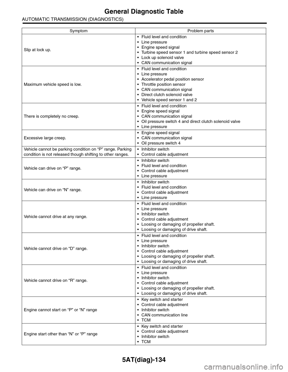
5AT(diag)-134
General Diagnostic Table
AUTOMATIC TRANSMISSION (DIAGNOSTICS)
Slip at lock up.
•Fluid level and condition
•Line pressure
•Engine speed signal
•Turbine speed sensor 1 and turbine speed sensor 2
•Lock up solenoid valve
•CAN communication signal
Maximum vehicle speed is low.
•Fluid level and condition
•Line pressure
•Accelerator pedal position sensor
•Throttle position sensor
•CAN communication signal
•Direct clutch solenoid valve
•Vehicle speed sensor 1 and 2
There is completely no creep.
•Fluid level and condition
•Engine speed signal
•CAN communication signal
•Oil pressure switch 4 and direct clutch solenoid valve
•Line pressure
Excessive large creep.
•Engine speed signal
•CAN communication signal
•Oil pressure switch 4
Ve h i c l e c a n n o t b e p a r k i n g c o n d i t i o n o n “ P ” r a n g e . Pa r k i n g
condition is not released though shifting to other ranges.
•Inhibitor switch
•Control cable adjustment
Ve h i c l e c a n d r i v e o n “ P ” r a n g e .
•Inhibitor switch
•Fluid level and condition
•Control cable adjustment
•Line pressure
Ve h i c l e c a n d r i v e o n “ N ” r a n g e .
•Inhibitor switch
•Fluid level and condition
•Control cable adjustment
•Line pressure
Ve h i c l e c a n n o t d r i v e a t a n y r a n g e .
•Fluid level and condition
•Line pressure
•Inhibitor switch
•Control cable adjustment
•Loosing or damaging of propeller shaft.
•Loosing or damaging of drive shaft.
Ve h i c l e c a n n o t d r i v e o n “ D ” r a n g e .
•Fluid level and condition
•Line pressure
•Inhibitor switch
•Control cable adjustment
•Loosing or damaging of propeller shaft.
•Loosing or damaging of drive shaft.
Ve h i c l e c a n n o t d r i v e o n “ R ” r a n g e .
•Fluid level and condition
•Line pressure
•Inhibitor switch
•Control cable adjustment
•Loosing or damaging of propeller shaft.
•Loosing or damaging of drive shaft.
Engine cannot start on “P” or “N” range
•Key switch and starter
•Control cable adjustment
•Inhibitor switch
•CAN communication line
•TCM
Engine start other than “N” or “P” range
•Key switch and starter
•Control cable adjustment
•Inhibitor switch
•TCM
Symptom Problem parts
Page 2252 of 2453
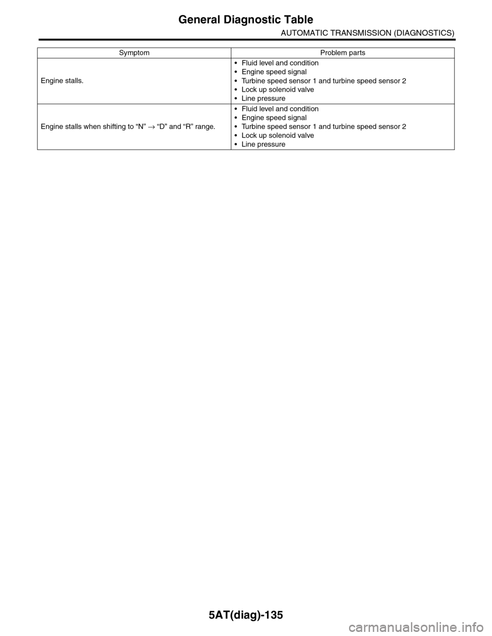
5AT(diag)-135
General Diagnostic Table
AUTOMATIC TRANSMISSION (DIAGNOSTICS)
Engine stalls.
•Fluid level and condition
•Engine speed signal
•Turbine speed sensor 1 and turbine speed sensor 2
•Lock up solenoid valve
•Line pressure
Engine stalls when shifting to “N” → “D” and “R” range.
•Fluid level and condition
•Engine speed signal
•Turbine speed sensor 1 and turbine speed sensor 2
•Lock up solenoid valve
•Line pressure
Symptom Problem parts
Page 2253 of 2453
5AT(diag)-136
General Diagnostic Table
AUTOMATIC TRANSMISSION (DIAGNOSTICS)
Page 2254 of 2453
CS-2
General Description
CONTROL SYSTEMS
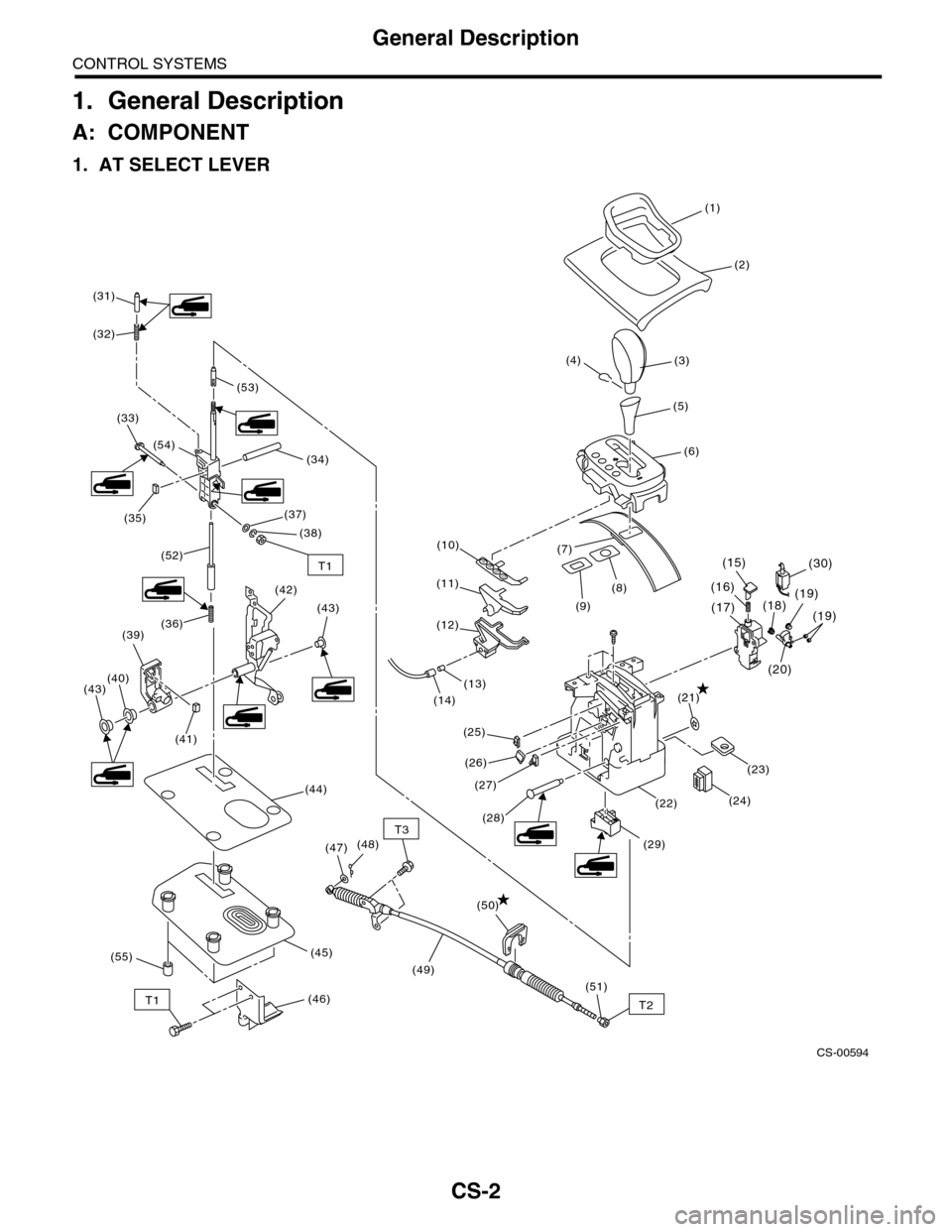
1. General Description
A: COMPONENT
1. AT SELECT LEVER
CS-00594
PRND
(1)
(31)
(32)
(33)
(34)
(37)(35)
(2)
(3)
(5)
(6)
(7)
(8)
(9)
(10)
(11)
(12)
(13)
(23)
(14)(21)
(25)
(17)(18)(19)
(20)
(19)
(16)
(26)
(27)
(4)
(48)(47)
(51)
(49)
(50)
(55)
T2
T3
(24)(22)
(29)
(15)
(28)
(54)
(44)
(45)
(46)
(38)
(40)(43)
(39)(36)
(52)
(43)
(42)
(41)
(53)
(30)T1
T1
Page 2255 of 2453
CS-3
General Description
CONTROL SYSTEMS
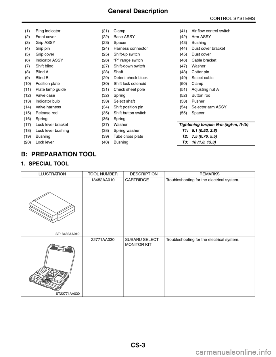
B: PREPARATION TOOL
1. SPECIAL TOOL
(1) Ring indicator (21) Clamp (41) Air flow control switch
(2) Front cover (22) Base ASSY (42) Arm ASSY
(3) Grip ASSY (23) Spacer (43) Bushing
(4) Grip pin (24) Harness connector (44) Dust cover bracket
(5) Grip cover (25) Shift-up switch (45) Dust cover
(6) Indicator ASSY (26) “P” range switch (46) Cable bracket
(7) Shift blind (27) Shift-down switch (47) Washer
(8) Blind A (28) Shaft (48) Cotter pin
(9) Blind B (29) Detent check block (49) Select cable
(10) Position plate (30) Shift lock solenoid (50) Clamp
(11) Plate lamp guide (31) Check sheet pole (51) Adjusting nut A
(12) Valve case (32) Spring (52) Button rod
(13) Indicator bulb (33) Select shaft (53) Pusher
(14) Valve harness (34) Shift position pin (54) Selector arm ASSY
(15) Release rod (35) Shift button switch (55) Spacer
(16) Spring (36) Spring
(17) Lock lever bracket (37) WasherTightening torque: N·m (kgf-m, ft-lb)
(18) Lock lever bushing (38) Spring washerT1: 5.1 (0.52, 3.8)
(19) Bushing (39) Tube cross plateT2: 7.5 (0.76, 5.5)
(20) Lock lever (40) BushingT3: 18 (1.8, 13.3)
ILLUSTRATION TOOL NUMBER DESCRIPTION REMARKS
18482AA010 CARTRIDGE Troubleshooting for the electrical system.
22771AA030 SUBARU SELECT
MONITOR KIT
Tr o u b l e s h o o t i n g f o r t h e e l e c t r i c a l s y s t e m .
ST18482AA010
ST22771AA030
Page 2256 of 2453
CS-4
General Description
CONTROL SYSTEMS
C: CAUTION
•Wear work clothing, including a cap, protective
goggles and protective shoes during operation.
•Remove contamination including dirt and corro-
sion before removal, installation or disassembly.
•Keep the disassembled parts in order and pro-
tect them from dust and dirt.
•Before removal, installation or disassembly, be
sure to clarify the failure. Avoid unnecessary re-
moval, installation, disassembly and replacement.
•Use SUBARU genuine fluid, grease etc. or
equivalent. Do not mix fluid, grease, etc. with that of
another grade or from other manufacturers.
•Be sure to tighten fasteners including bolts and
nuts to the specified torque.
•Place shop jacks or rigid racks at the specified
points.
•Apply grease onto sliding or revolution surfaces
before installation.
•Before installing O-rings or snap rings, apply suf-
ficient amount of fluid to avoid damage and defor-
mation.
•Before securing a part in a vise, place cushioning
material such as wood blocks, aluminum plate or
cloth between the part and the vise.
•Before disconnecting electrical connectors, be
sure to disconnect the negative terminal from bat-
tery.
Page 2257 of 2453
CS-5
AT Shift Lock Control System
CONTROL SYSTEMS
2. AT Shift Lock Control System
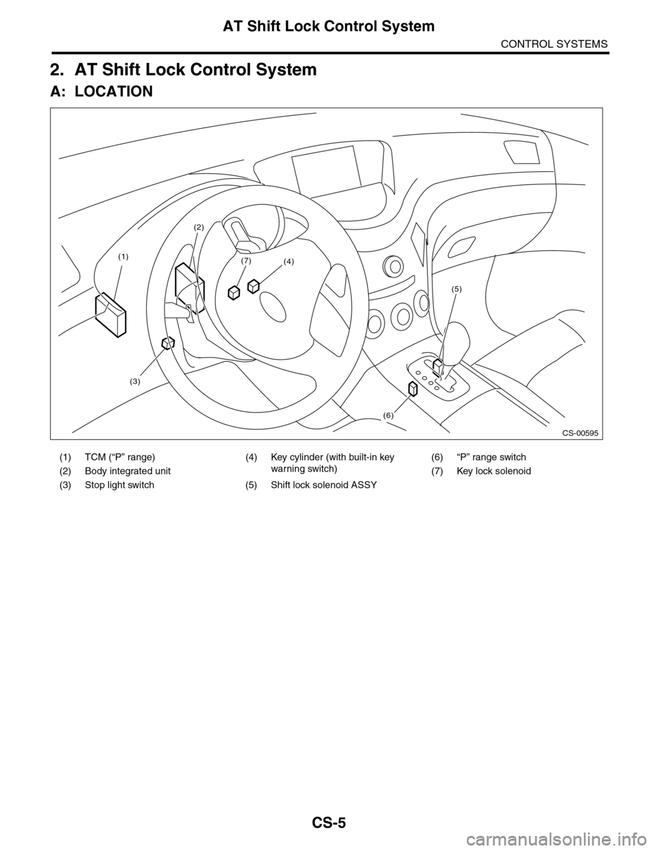
A: LOCATION
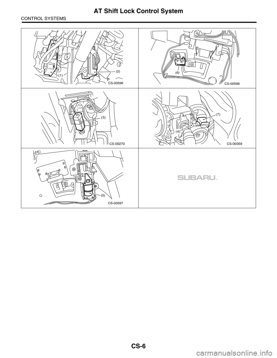
(1) TCM (“P” range) (4) Key cylinder (with built-in key
warning switch)
(6) “P” range switch
(2) Body integrated unit (7) Key lock solenoid
(3) Stop light switch (5) Shift lock solenoid ASSY
CS-00595
(4)
(6)
(5)
(7)(1)
(2)
(3)
Page 2258 of 2453
CS-6
AT Shift Lock Control System
CONTROL SYSTEMS
CS-00596
(2)(1)
CS-00598
(6)
(3)
CS-00270CS-00359
(7)
(4)
CS-00597
(5)
Page 2259 of 2453
CS-7
AT Shift Lock Control System
CONTROL SYSTEMS
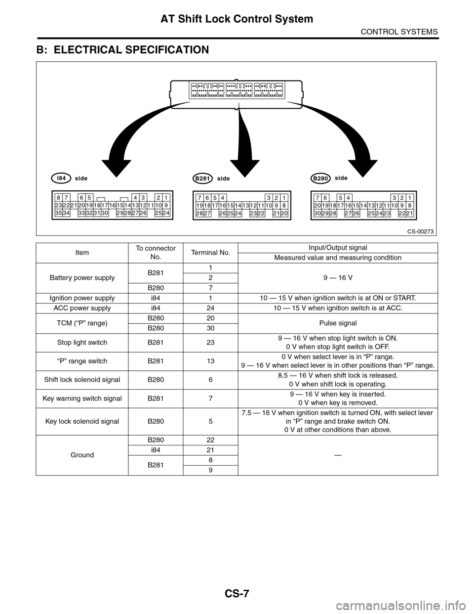
B: ELECTRICAL SPECIFICATION
ItemTo c o n n e c t o r
No.Te r m i n a l N o .Input/Output signal
Measured value and measuring condition
Battery power supplyB2811
9 — 16 V2
B280 7
Ignition power supply i84 1 10 — 15 V when ignition switch is at ON or START.
ACC power supply i84 24 10 — 15 V when ignition switch is at ACC.
TCM (“P” range)B280 20Pulse signalB280 30
Stop light switch B281 239 — 16 V when stop light switch is ON.
0 V when stop light switch is OFF.
“P” range switch B281 130 V when select lever is in “P” range.
9 — 16 V when select lever is in other positions than “P” range.
Shift lock solenoid signal B280 68.5 — 16 V when shift lock is released.
0 V when shift lock is operating.
Key war ning switch signal B281 79 — 16 V when key is inserted.
0 V when key is removed.
Key lock solenoid signal B280 5
7.5 — 16 V when ignition switch is turned ON, with select lever
in “P” range and brake switch ON.
0 V at other conditions than above.
Ground
B280 22
—i84 21
B2818
9
CS-00273
71928
61827
51741626152514241312231122
3102921
1820
B281side
72030
619291828
51741627152614132512241123
3102922
1821
B280side
82335
722342162033
51932183117301615291428
41327
312261121025
1924
i84side
Page 2260 of 2453
CS-8
AT Shift Lock Control System
CONTROL SYSTEMS
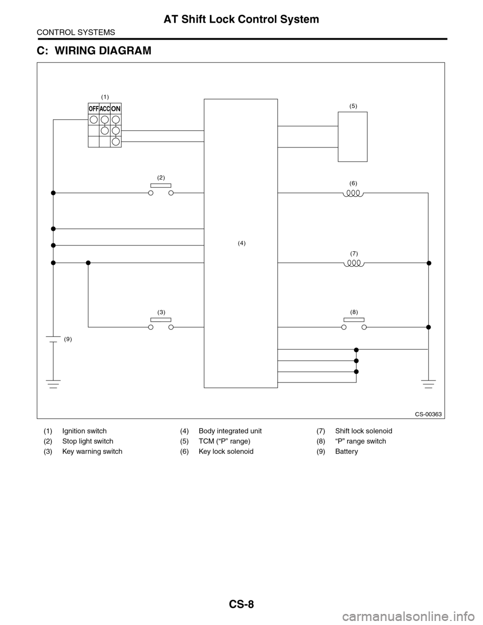
C: WIRING DIAGRAM
(1) Ignition switch (4) Body integrated unit (7) Shift lock solenoid
(2) Stop light switch (5) TCM (“P” range) (8) “P” range switch
(3) Key warning switch (6) Key lock solenoid (9) Battery
CS-00363
OFFACCON
(1)
(2)
(3)
(4)
(9)
(6)
(7)
(8)
(5)