instrument panel SUBARU TRIBECA 2009 1.G Service Owner's Guide
[x] Cancel search | Manufacturer: SUBARU, Model Year: 2009, Model line: TRIBECA, Model: SUBARU TRIBECA 2009 1.GPages: 2453, PDF Size: 46.32 MB
Page 350 of 2453
AC-24
Refrigerant Leak Check
HVAC SYSTEM (HEATER, VENTILATOR AND A/C)
5. Refrigerant Leak Check
A: INSPECTION
1) At engine speed below 1500rpm, operate the A/
C system for approx. 10 minutes, and confirm that
the high-side pressure shows at least 690 kPa
(7.03 kg/cm2, 100 psi). Then stop the engine to
start the leak test.
2) Starting from the connection between high-pres-
sure pipe and evaporator, check the system for
leaks along the high-pressure side through the
compressor. The following items must be checked
thoroughly.
3) Check the joint and seam between pressure
switch (dual switch) and high-pressure pipe.
4) Check the connections between condenser and
pipes, and welded joints on the condenser.
The leak tester may detect the oil on the condenser
fins as a leak.
5) Check the joint between compressor and hoses.
6) Check the machined area of the compressor and
other joints on the compressor.
7) Check the compressor shaft seal at the area
near the center of compressor clutch pulley.
Some shaft seals show a slight amount of leakage,
about 3 g (0.1 oz) per year. This is not a problem.
8) Starting from the connection between low-pres-
sure pipe and evaporator, check the system for
leakage along the low-pressure side through the
compressor. The following items must be checked
thoroughly.
•Connection between 2 parts
•Connection between pipe and plate
•Connection between pipes
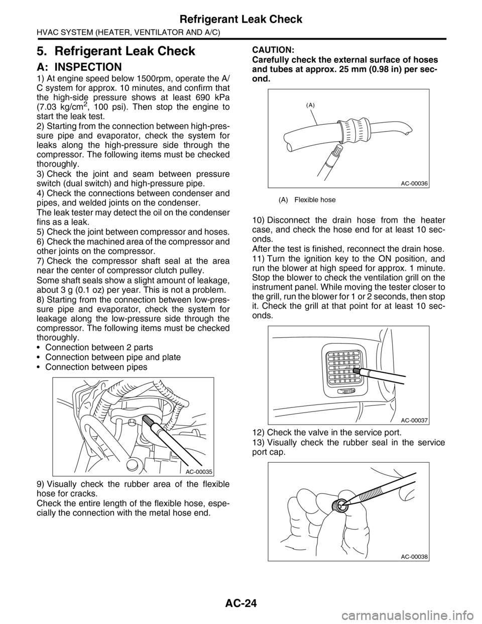
9) Visually check the rubber area of the flexible
hose for cracks.
Check the entire length of the flexible hose, espe-
cially the connection with the metal hose end.
CAUTION:
Carefully check the external surface of hoses
and tubes at approx. 25 mm (0.98 in) per sec-
ond.
10) Disconnect the drain hose from the heater
case, and check the hose end for at least 10 sec-
onds.
After the test is finished, reconnect the drain hose.
11) Turn the ignition key to the ON position, and
run the blower at high speed for approx. 1 minute.
Stop the blower to check the ventilation grill on the
instrument panel. While moving the tester closer to
the grill, run the blower for 1 or 2 seconds, then stop
it. Check the grill at that point for at least 10 sec-
onds.
12) Check the valve in the service port.
13) Visually check the rubber seal in the service
port cap.
AC-00035
(A) Flexible hose
AC-00036
(A)
AC-00037
AC-00038
Page 357 of 2453
AC-31
Control Panel
HVAC SYSTEM (HEATER, VENTILATOR AND A/C)
12.Control Panel
A: REMOVAL
1. FRONT
1) Disconnect the ground cable from battery.
2) Remove the front console panel.
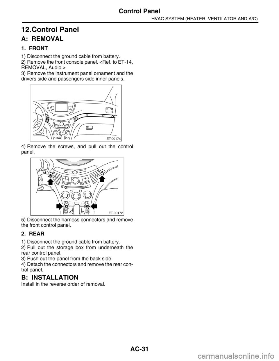
3) Remove the instrument panel ornament and the
drivers side and passengers side inner panels.
4) Remove the screws, and pull out the control
panel.
5) Disconnect the harness connectors and remove
the front control panel.
2. REAR
1) Disconnect the ground cable from battery.
2) Pull out the storage box from underneath the
rear control panel.
3) Push out the panel from the back side.
4) Detach the connectors and remove the rear con-
trol panel.
B: INSTALLATION
Install in the reverse order of removal.
ET-00174
ET-00172
Page 361 of 2453
AC-35
Heater and Cooling Unit
HVAC SYSTEM (HEATER, VENTILATOR AND A/C)
16.Heater and Cooling Unit
A: REMOVAL
1. FRONT
1) Disconnect the ground cable from battery.
2) Using the refrigerant recovery system, dis-
charge refrigerant.
3) Drain engine coolant from the radiator.
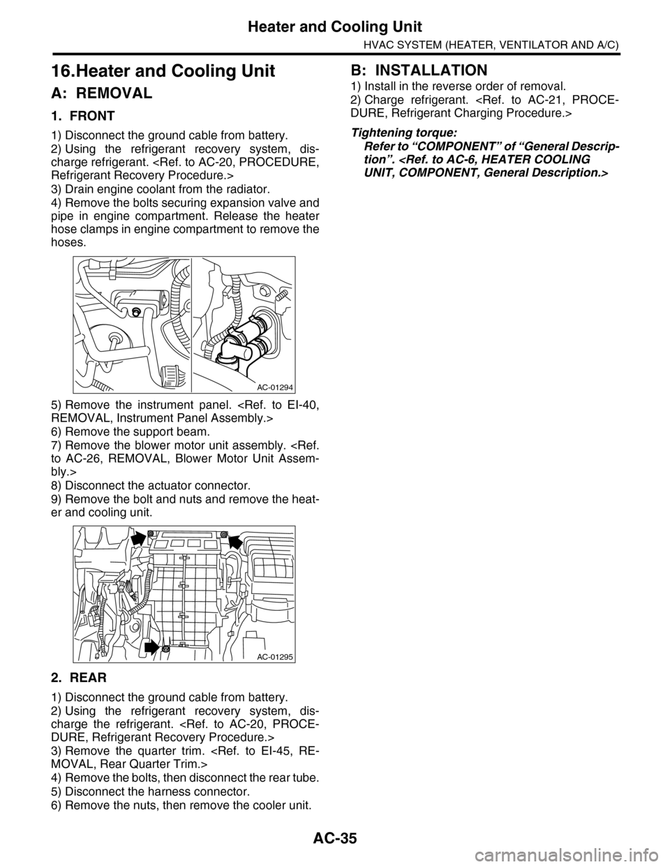
4) Remove the bolts securing expansion valve and
pipe in engine compartment. Release the heater
hose clamps in engine compartment to remove the
hoses.
5) Remove the instrument panel.
6) Remove the support beam.
7) Remove the blower motor unit assembly.
bly.>
8) Disconnect the actuator connector.
9) Remove the bolt and nuts and remove the heat-
er and cooling unit.
2. REAR
1) Disconnect the ground cable from battery.
2) Using the refrigerant recovery system, dis-
charge the refrigerant.
3) Remove the quarter trim.
4) Remove the bolts, then disconnect the rear tube.
5) Disconnect the harness connector.
6) Remove the nuts, then remove the cooler unit.
B: INSTALLATION
1) Install in the reverse order of removal.
2) Charge refrigerant.
Tightening torque:
Refer to “COMPONENT” of “General Descrip-
tion”.
AC-01294
AC-01295
Page 371 of 2453
AC-45
In-vehicle Sensor (Auto A/C Model)
HVAC SYSTEM (HEATER, VENTILATOR AND A/C)
24.In-vehicle Sensor (Auto A/C
Model)
A: REMOVAL
1) Disconnect the ground cable from battery.
2) Remove the instrument panel lower panel on
driver’s side.
3) Disconnect the connector and aspirator hose,
remove the catch hook and remove the interior
temperature sensor from the knee guard plate.
CAUTION:
Be careful not to damage the sensors and inte-
rior trim when removing.
B: INSTALLATION
Install in the reverse order of removal.
C: INSPECTION
Page 373 of 2453
AC-47
Heater Duct
HVAC SYSTEM (HEATER, VENTILATOR AND A/C)
26.Heater Duct
A: REMOVAL
1. FRONT HEATER DUCT
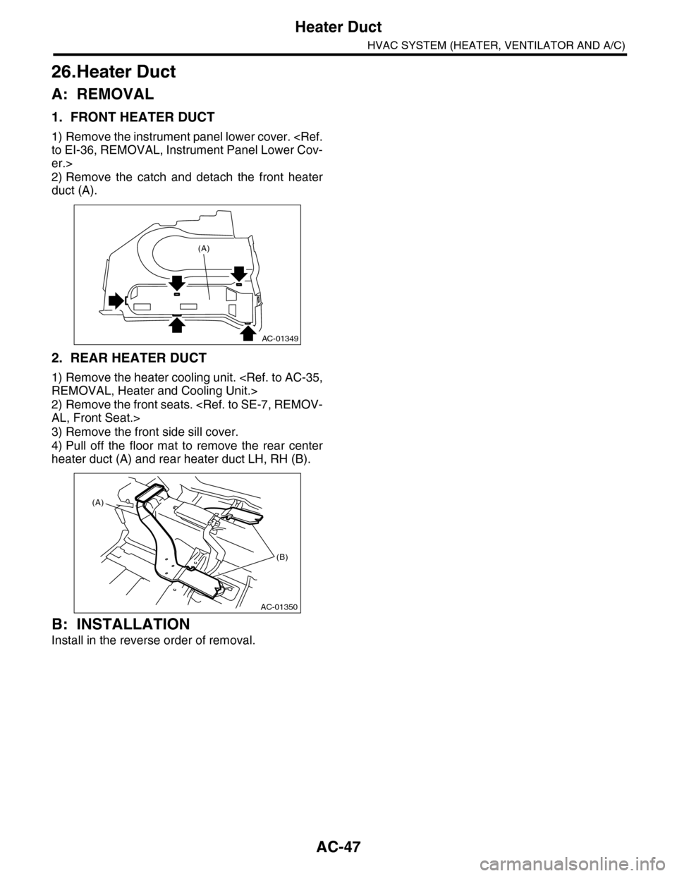
1) Remove the instrument panel lower cover.
er.>
2) Remove the catch and detach the front heater
duct (A).
2. REAR HEATER DUCT
1) Remove the heater cooling unit.
2) Remove the front seats.
3) Remove the front side sill cover.
4) Pull off the floor mat to remove the rear center
heater duct (A) and rear heater duct LH, RH (B).
B: INSTALLATION
Install in the reverse order of removal.
AC-01349
(A)
AC-01350
(A)
(B)
Page 374 of 2453
AC-48
Heater Vent Duct
HVAC SYSTEM (HEATER, VENTILATOR AND A/C)
27.Heater Vent Duct
A: REMOVAL
1. INSTRUMENT
1) Remove the instrument panel.
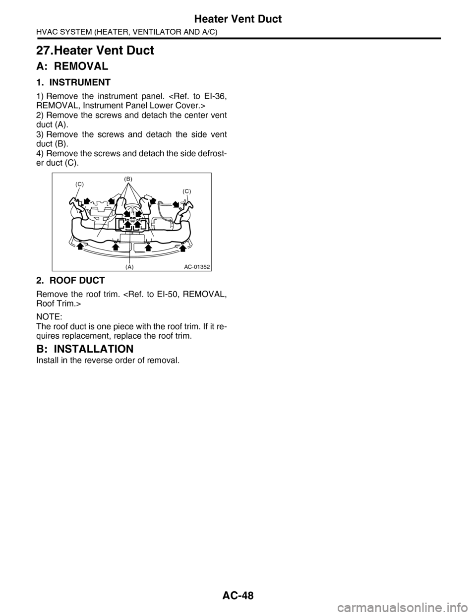
2) Remove the screws and detach the center vent
duct (A).
3) Remove the screws and detach the side vent
duct (B).
4) Remove the screws and detach the side defrost-
er duct (C).
2. ROOF DUCT
Remove the roof trim.
NOTE:
The roof duct is one piece with the roof trim. If it re-
quires replacement, replace the roof trim.
B: INSTALLATION
Install in the reverse order of removal.
AC-01352
(C)(B)
(C)
(A)
Page 375 of 2453
AC-49
A/C Filter
HVAC SYSTEM (HEATER, VENTILATOR AND A/C)
28.A/C Filter
A: REPLACEMENT
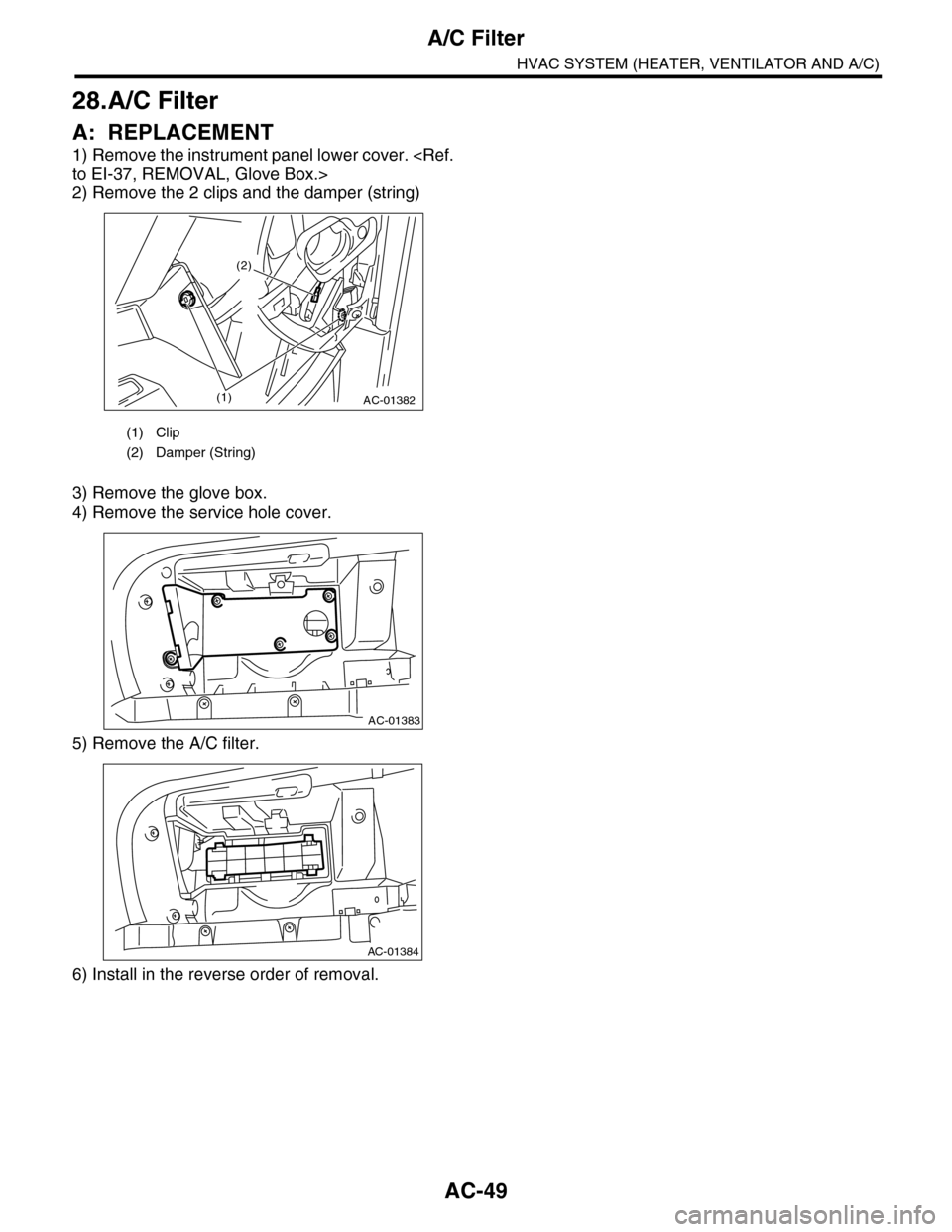
1) Remove the instrument panel lower cover.
2) Remove the 2 clips and the damper (string)
3) Remove the glove box.
4) Remove the service hole cover.
5) Remove the A/C filter.
6) Install in the reverse order of removal.
(1) Clip
(2) Damper (String)
AC-01382(1)
(2)
AC-01383
AC-01384
Page 423 of 2453
IM (diag)-7
Subaru Select Monitor
IMMOBILIZER (DIAGNOSTICS)
5. Subaru Select Monitor
A: OPERATION
1. HOW TO USE SUBARU SELECT MONI-
TOR
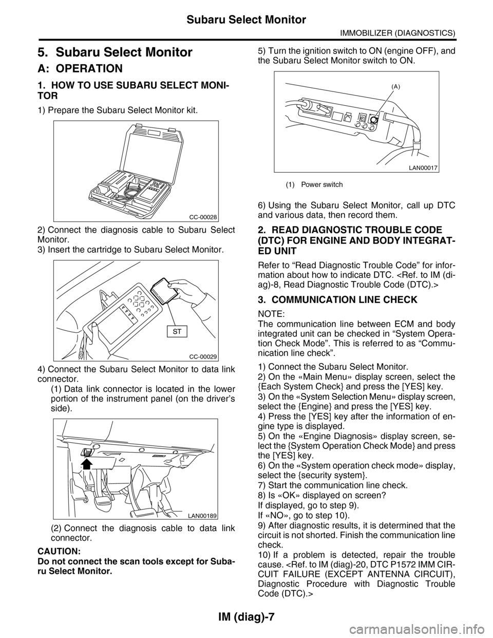
1) Prepare the Subaru Select Monitor kit.
2) Connect the diagnosis cable to Subaru Select
Monitor.
3) Insert the cartridge to Subaru Select Monitor.
4) Connect the Subaru Select Monitor to data link
connector.
(1) Data link connector is located in the lower
portion of the instrument panel (on the driver’s
side).
(2) Connect the diagnosis cable to data link
connector.
CAUTION:
Do not connect the scan tools except for Suba-
ru Select Monitor.
5) Turn the ignition switch to ON (engine OFF), and
the Subaru Select Monitor switch to ON.
6) Using the Subaru Select Monitor, call up DTC
and various data, then record them.
2. READ DIAGNOSTIC TROUBLE CODE
(DTC) FOR ENGINE AND BODY INTEGRAT-
ED UNIT
Refer to “Read Diagnostic Trouble Code” for infor-
mation about how to indicate DTC.
3. COMMUNICATION LINE CHECK
NOTE:
The communication line between ECM and body
integrated unit can be checked in “System Opera-
tion Check Mode”. This is referred to as “Commu-
nication line check”.
1) Connect the Subaru Select Monitor.
2) On the «Main Menu» display screen, select the
{Each System Check} and press the [YES] key.
3) On the «System Selection Menu» display screen,
select the {Engine} and press the [YES] key.
4) Press the [YES] key after the information of en-
gine type is displayed.
5) On the «Engine Diagnosis» display screen, se-
lect the {System Operation Check Mode} and press
the [YES] key.
6) On the «System operation check mode» display,
select the {security system}.
7) Start the communication line check.
8) Is «OK» displayed on screen?
If displayed, go to step 9).
If «NO», go to step 10).
9) After diagnostic results, it is determined that the
circuit is not shorted. Finish the communication line
check.
10) If a problem is detected, repair the trouble
cause.
Diagnostic Procedure with Diagnostic Trouble
Code (DTC).>
CC-00028
CC-00029
LAN00189
(1) Power switch
LAN00017
(A)
Page 442 of 2453
IDI-3
General Description
INSTRUMENTATION/DRIVER INFO
B: CAUTION
•Be careful not to damage the meters and instrument panel.
•Be careful not to damage the meter glass.
•Make sure the electrical connector is connected securely.
•After installation, make sure that each meter operates normally.
•Use gloves to avoid damage and getting fingerprints on the glass surface and meter surfaces.
•Do not apply an excessive force on the printed circuit.
•Do not drop or otherwise apply impact.
•When the combination meter of model with immobilizer has been replaced, be sure to perform the regis-
tration of immobilizer.
C: PREPARATION TOOL
1. GENERAL TOOL
TOOL NAME REMARKS
Circuit tester Used for measuring resistance and voltage.
Page 450 of 2453
IDI-11
Combination Meter
INSTRUMENTATION/DRIVER INFO
3. Combination Meter
A: REMOVAL
1) Disconnect the ground cable from battery.
2) Set the tilt steering at the lowest position.
3) Remove the console box.
4) Remove the control panel.
5) Remove the instrument panel lower cover.
er.>
6) Remove the console side panel.
7) Remove the meter hood.
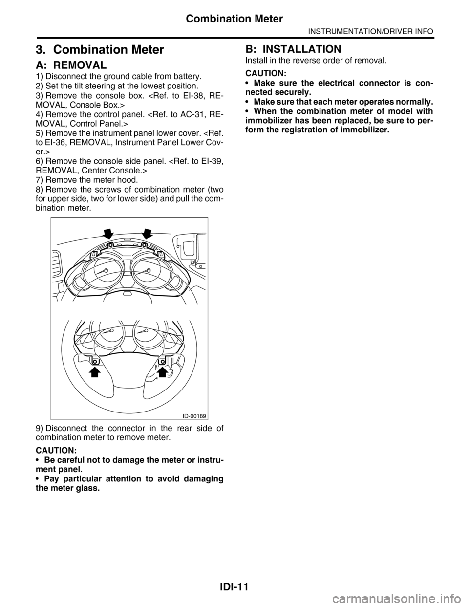
8) Remove the screws of combination meter (two
for upper side, two for lower side) and pull the com-
bination meter.
9) Disconnect the connector in the rear side of
combination meter to remove meter.
CAUTION:
•Be careful not to damage the meter or instru-
ment panel.
•Pay particular attention to avoid damaging
the meter glass.
B: INSTALLATION
Install in the reverse order of removal.
CAUTION:
•Make sure the electrical connector is con-
nected securely.
•Make sure that each meter operates normally.
•When the combination meter of model with
immobilizer has been replaced, be sure to per-
form the registration of immobilizer.
ID-00189