sensor SUBARU TRIBECA 2009 1.G Service Workshop Manual
[x] Cancel search | Manufacturer: SUBARU, Model Year: 2009, Model line: TRIBECA, Model: SUBARU TRIBECA 2009 1.GPages: 2453, PDF Size: 46.32 MB
Page 1397 of 2453
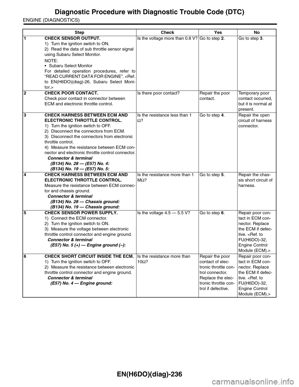
EN(H6DO)(diag)-236
Diagnostic Procedure with Diagnostic Trouble Code (DTC)
ENGINE (DIAGNOSTICS)
Step Check Yes No
1CHECK SENSOR OUTPUT.
1) Turn the ignition switch to ON.
2) Read the data of sub throttle sensor signal
using Subaru Select Monitor.
NOTE:•Subaru Select Monitor
For detailed operation procedures, refer to
“READ CURRENT DATA FOR ENGINE”.
tor.>
Is the voltage more than 0.8 V? Go to step 2.Go to step 3.
2CHECK POOR CONTACT.
Check poor contact in connector between
ECM and electronic throttle control.
Is there poor contact? Repair the poor
contact.
Te m p o r a r y p o o r
contact occurred,
but it is normal at
present.
3CHECK HARNESS BETWEEN ECM AND
ELECTRONIC THROTTLE CONTROL.
1) Turn the ignition switch to OFF.
2) Disconnect the connectors from ECM.
3) Disconnect the connectors from electronic
throttle control.
4) Measure the resistance between ECM con-
nector and electronic throttle control connector.
Connector & terminal
(B134) No. 28 — (E57) No. 4:
(B134) No. 19 — (E57) No. 5:
Is the resistance less than 1
Ω?
Go to step 4.Repair the open
circuit of harness
connector.
4CHECK HARNESS BETWEEN ECM AND
ELECTRONIC THROTTLE CONTROL.
Measure the resistance between ECM connec-
tor and chassis ground.
Connector & terminal
(B134) No. 28 — Chassis ground:
(B134) No. 19 — Chassis ground:
Is the resistance more than 1
MΩ?
Go to step 5.Repair the chas-
sis short circuit of
harness.
5CHECK SENSOR POWER SUPPLY.
1) Connect the ECM connector.
2) Turn the ignition switch to ON.
3) Measure the voltage between electronic
throttle control connector and engine ground.
Connector & terminal
(E57) No. 5 (+) — Engine ground (–):
Is the voltage 4.5 — 5.5 V? Go to step 6.Repair poor con-
tact in ECM con-
nector. Replace
the ECM if defec-
tive.
Engine Control
Module (ECM).>
6CHECK SHORT CIRCUIT INSIDE THE ECM.
1) Turn the ignition switch to OFF.
2) Measure the resistance between electronic
throttle control connector and engine ground.
Connector & terminal
(E57) No. 4 — Engine ground:
Is the resistance more than
10Ω?
Repair the poor
contact of elec-
tronic throttle con-
trol connector.
Replace the elec-
tronic throttle con-
trol if defective.
Repair poor con-
tact in ECM con-
nector. Replace
the ECM if defec-
tive.
Engine Control
Module (ECM).>
Page 1398 of 2453
EN(H6DO)(diag)-237
Diagnostic Procedure with Diagnostic Trouble Code (DTC)
ENGINE (DIAGNOSTICS)
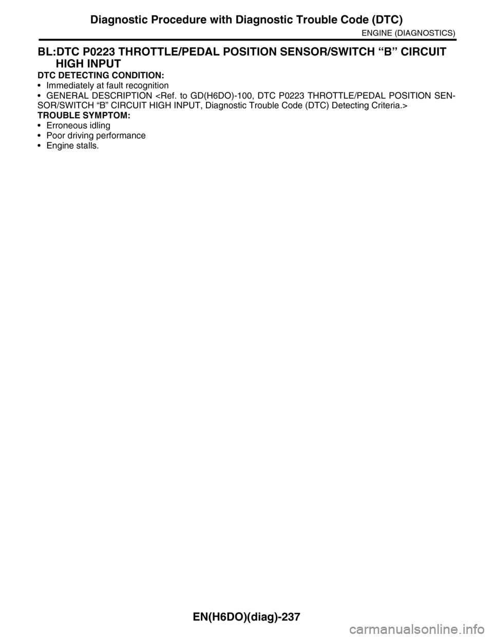
BL:DTC P0223 THROTTLE/PEDAL POSITION SENSOR/SWITCH “B” CIRCUIT
HIGH INPUT
DTC DETECTING CONDITION:
•Immediately at fault recognition
•GENERAL DESCRIPTION
TROUBLE SYMPTOM:
•Erroneous idling
•Poor driving performance
•Engine stalls.
Page 1400 of 2453
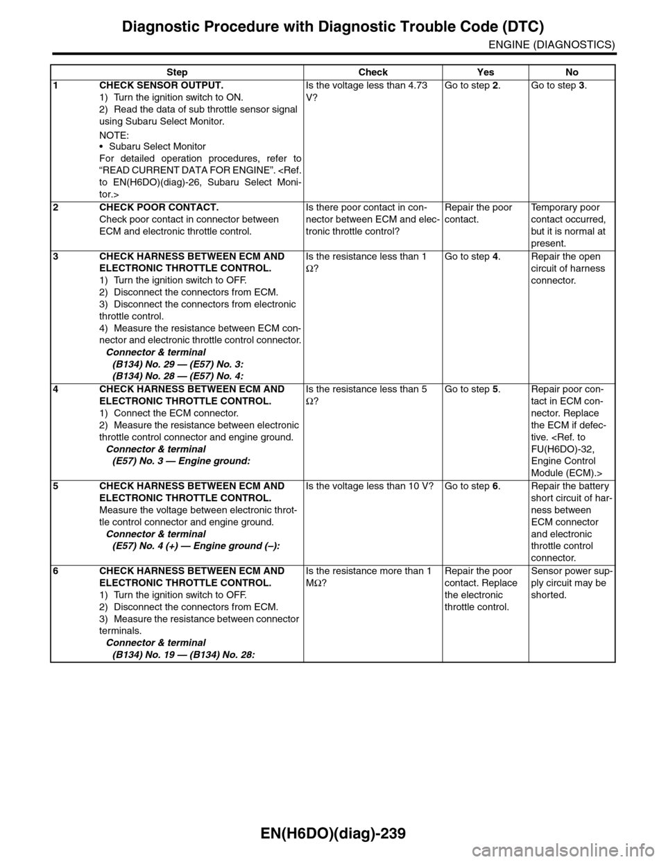
EN(H6DO)(diag)-239
Diagnostic Procedure with Diagnostic Trouble Code (DTC)
ENGINE (DIAGNOSTICS)
Step Check Yes No
1CHECK SENSOR OUTPUT.
1) Turn the ignition switch to ON.
2) Read the data of sub throttle sensor signal
using Subaru Select Monitor.
NOTE:•Subaru Select Monitor
For detailed operation procedures, refer to
“READ CURRENT DATA FOR ENGINE”.
tor.>
Is the voltage less than 4.73
V?
Go to step 2.Go to step 3.
2CHECK POOR CONTACT.
Check poor contact in connector between
ECM and electronic throttle control.
Is there poor contact in con-
nector between ECM and elec-
tronic throttle control?
Repair the poor
contact.
Te m p o r a r y p o o r
contact occurred,
but it is normal at
present.
3CHECK HARNESS BETWEEN ECM AND
ELECTRONIC THROTTLE CONTROL.
1) Turn the ignition switch to OFF.
2) Disconnect the connectors from ECM.
3) Disconnect the connectors from electronic
throttle control.
4) Measure the resistance between ECM con-
nector and electronic throttle control connector.
Connector & terminal
(B134) No. 29 — (E57) No. 3:
(B134) No. 28 — (E57) No. 4:
Is the resistance less than 1
Ω?
Go to step 4.Repair the open
circuit of harness
connector.
4CHECK HARNESS BETWEEN ECM AND
ELECTRONIC THROTTLE CONTROL.
1) Connect the ECM connector.
2) Measure the resistance between electronic
throttle control connector and engine ground.
Connector & terminal
(E57) No. 3 — Engine ground:
Is the resistance less than 5
Ω?
Go to step 5.Repair poor con-
tact in ECM con-
nector. Replace
the ECM if defec-
tive.
Engine Control
Module (ECM).>
5CHECK HARNESS BETWEEN ECM AND
ELECTRONIC THROTTLE CONTROL.
Measure the voltage between electronic throt-
tle control connector and engine ground.
Connector & terminal
(E57) No. 4 (+) — Engine ground (–):
Is the voltage less than 10 V? Go to step 6.Repair the battery
short circuit of har-
ness between
ECM connector
and electronic
throttle control
connector.
6CHECK HARNESS BETWEEN ECM AND
ELECTRONIC THROTTLE CONTROL.
1) Turn the ignition switch to OFF.
2) Disconnect the connectors from ECM.
3) Measure the resistance between connector
terminals.
Connector & terminal
(B134) No. 19 — (B134) No. 28:
Is the resistance more than 1
MΩ?
Repair the poor
contact. Replace
the electronic
throttle control.
Sensor power sup-
ply circuit may be
shorted.
Page 1407 of 2453
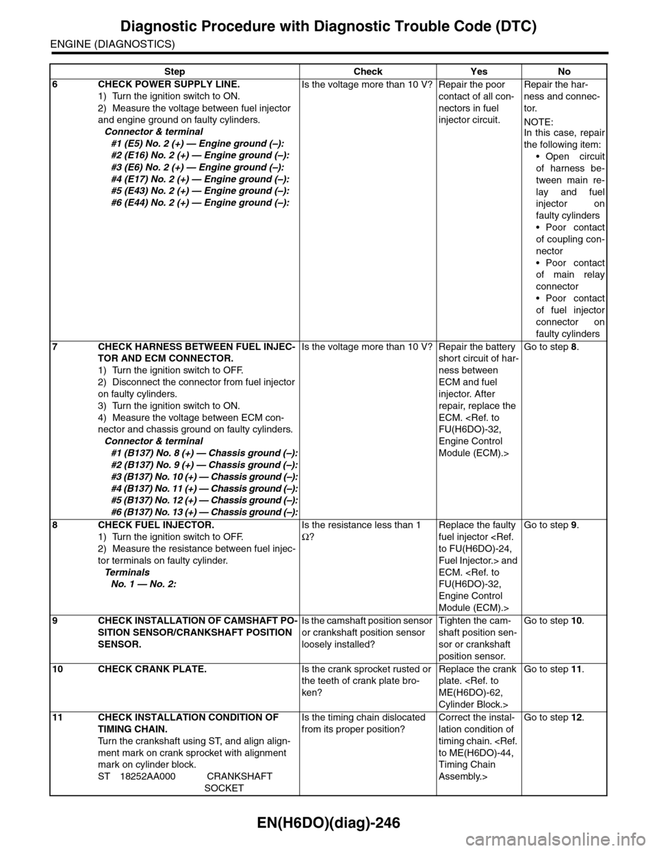
EN(H6DO)(diag)-246
Diagnostic Procedure with Diagnostic Trouble Code (DTC)
ENGINE (DIAGNOSTICS)
6CHECK POWER SUPPLY LINE.
1) Turn the ignition switch to ON.
2) Measure the voltage between fuel injector
and engine ground on faulty cylinders.
Connector & terminal
#1 (E5) No. 2 (+) — Engine ground (–):
#2 (E16) No. 2 (+) — Engine ground (–):
#3 (E6) No. 2 (+) — Engine ground (–):
#4 (E17) No. 2 (+) — Engine ground (–):
#5 (E43) No. 2 (+) — Engine ground (–):
#6 (E44) No. 2 (+) — Engine ground (–):
Is the voltage more than 10 V? Repair the poor
contact of all con-
nectors in fuel
injector circuit.
Repair the har-
ness and connec-
tor.
NOTE:In this case, repair
the following item:
•Open circuit
of harness be-
tween main re-
lay and fuel
injector on
faulty cylinders
•Poor contact
of coupling con-
nector
•Poor contact
of main relay
connector
•Poor contact
of fuel injector
connector on
faulty cylinders
7CHECK HARNESS BETWEEN FUEL INJEC-
TOR AND ECM CONNECTOR.
1) Turn the ignition switch to OFF.
2) Disconnect the connector from fuel injector
on faulty cylinders.
3) Turn the ignition switch to ON.
4) Measure the voltage between ECM con-
nector and chassis ground on faulty cylinders.
Connector & terminal
#1 (B137) No. 8 (+) — Chassis ground (–):
#2 (B137) No. 9 (+) — Chassis ground (–):
#3 (B137) No. 10 (+) — Chassis ground (–):
#4 (B137) No. 11 (+) — Chassis ground (–):
#5 (B137) No. 12 (+) — Chassis ground (–):
#6 (B137) No. 13 (+) — Chassis ground (–):
Is the voltage more than 10 V? Repair the battery
short circuit of har-
ness between
ECM and fuel
injector. After
repair, replace the
ECM.
Engine Control
Module (ECM).>
Go to step 8.
8CHECK FUEL INJECTOR.
1) Turn the ignition switch to OFF.
2) Measure the resistance between fuel injec-
tor terminals on faulty cylinder.
Te r m i n a l s
No. 1 — No. 2:
Is the resistance less than 1
Ω?
Replace the faulty
fuel injector
Fuel Injector.> and
ECM.
Engine Control
Module (ECM).>
Go to step 9.
9CHECK INSTALLATION OF CAMSHAFT PO-
SITION SENSOR/CRANKSHAFT POSITION
SENSOR.
Is the camshaft position sensor
or crankshaft position sensor
loosely installed?
Tighten the cam-
shaft position sen-
sor or crankshaft
position sensor.
Go to step 10.
10 CHECK CRANK PLATE.Is the crank sprocket rusted or
the teeth of crank plate bro-
ken?
Replace the crank
plate.
Cylinder Block.>
Go to step 11.
11 CHECK INSTALLATION CONDITION OF
TIMING CHAIN.
Tu r n t h e c r a n k s h a f t u s i n g S T, a n d a l i g n a l i g n -
ment mark on crank sprocket with alignment
mark on cylinder block.
ST 18252AA000 CRANKSHAFT
SOCKET
Is the timing chain dislocated
from its proper position?
Correct the instal-
lation condition of
timing chain.
Timing Chain
Assembly.>
Go to step 12.
Step Check Yes No
Page 1412 of 2453
EN(H6DO)(diag)-251
Diagnostic Procedure with Diagnostic Trouble Code (DTC)
ENGINE (DIAGNOSTICS)
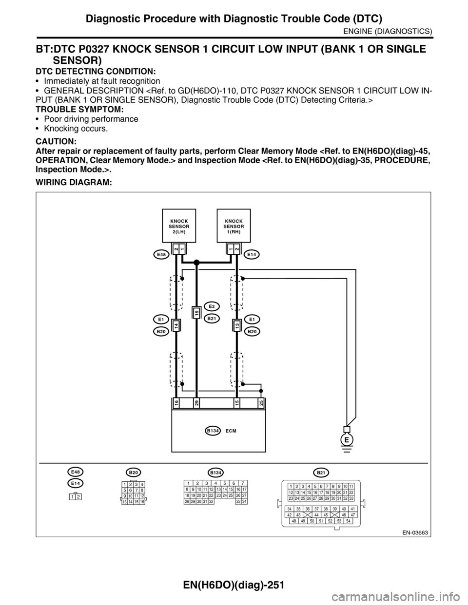
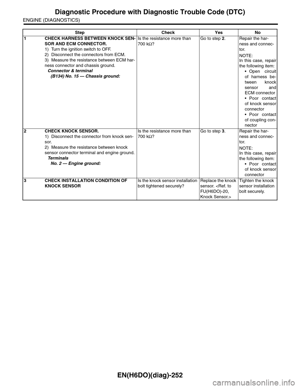
BT:DTC P0327 KNOCK SENSOR 1 CIRCUIT LOW INPUT (BANK 1 OR SINGLE
SENSOR)
DTC DETECTING CONDITION:
•Immediately at fault recognition
•GENERAL DESCRIPTION
TROUBLE SYMPTOM:
•Poor driving performance
•Knocking occurs.
CAUTION:
After repair or replacement of faulty parts, perform Clear Memory Mode
WIRING DIAGRAM:
EN-03663
152925
KNOCKSENSOR1(RH)
13
21
ECMB134
B20
E1B21
E2
B20
E1
E14
12
16
KNOCKSENSOR2(LH)
1414
19
13
E48E14
E48B20
1234567891011 121314 15 16
E
B134
85610 11 12 13 14 157213416
3019 20 2228 29
91718252123 24323126 2733 34
B21
12345678910 1112 13 14 15 16 17 18 19 20 21 2223 24 25 26 27 28 29 30 31 32 33
34 3542 4336 3738 39
48 4950 5152 5354
40 41444546 47
21
Page 1413 of 2453
EN(H6DO)(diag)-252
Diagnostic Procedure with Diagnostic Trouble Code (DTC)
ENGINE (DIAGNOSTICS)
Step Check Yes No
1CHECK HARNESS BETWEEN KNOCK SEN-
SOR AND ECM CONNECTOR.
1) Turn the ignition switch to OFF.
2) Disconnect the connectors from ECM.
3) Measure the resistance between ECM har-
ness connector and chassis ground.
Connector & terminal
(B134) No. 15 — Chassis ground:
Is the resistance more than
700 kΩ?
Go to step 2.Repair the har-
ness and connec-
tor.
NOTE:In this case, repair
the following item:
•Open circuit
of harness be-
tween knock
sensor and
ECM connector
•Poor contact
of knock sensor
connector
•Poor contact
of coupling con-
nector
2CHECK KNOCK SENSOR.
1) Disconnect the connector from knock sen-
sor.
2) Measure the resistance between knock
sensor connector terminal and engine ground.
Te r m i n a l s
No. 2 — Engine ground:
Is the resistance more than
700 kΩ?
Go to step 3.Repair the har-
ness and connec-
tor.
NOTE:In this case, repair
the following item:
•Poor contact
of knock sensor
connector
3CHECK INSTALLATION CONDITION OF
KNOCK SENSOR
Is the knock sensor installation
bolt tightened securely?
Replace the knock
sensor.
Knock Sensor.>
Tighten the knock
sensor installation
bolt securely.
Page 1414 of 2453
EN(H6DO)(diag)-253
Diagnostic Procedure with Diagnostic Trouble Code (DTC)
ENGINE (DIAGNOSTICS)
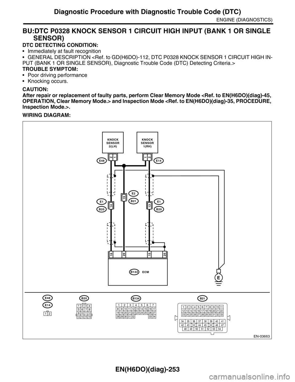
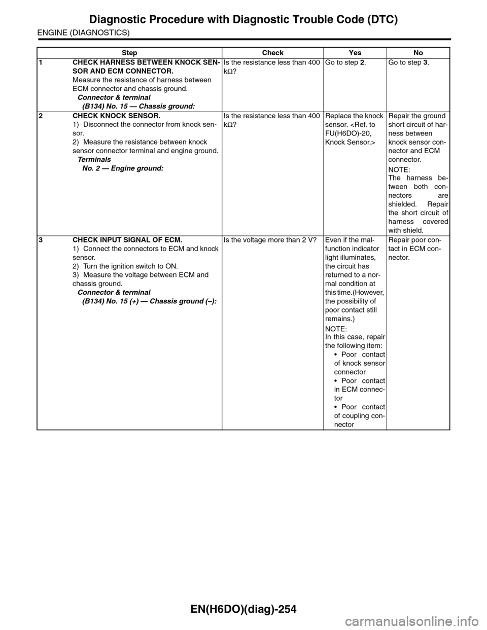
BU:DTC P0328 KNOCK SENSOR 1 CIRCUIT HIGH INPUT (BANK 1 OR SINGLE
SENSOR)
DTC DETECTING CONDITION:
•Immediately at fault recognition
•GENERAL DESCRIPTION
TROUBLE SYMPTOM:
•Poor driving performance
•Knocking occurs.
CAUTION:
After repair or replacement of faulty parts, perform Clear Memory Mode
WIRING DIAGRAM:
EN-03663
152925
KNOCKSENSOR1(RH)
13
21
ECMB134
B20
E1B21
E2
B20
E1
E14
12
16
KNOCKSENSOR2(LH)
1414
19
13
E48E14
E48B20
1234567891011 121314 15 16
E
B134
85610 11 12 13 14 157213416
3019 20 2228 29
91718252123 24323126 2733 34
B21
12345678910 1112 13 14 15 16 17 18 19 20 21 2223 24 25 26 27 28 29 30 31 32 33
34 3542 4336 3738 39
48 4950 5152 5354
40 41444546 47
21
Page 1415 of 2453
EN(H6DO)(diag)-254
Diagnostic Procedure with Diagnostic Trouble Code (DTC)
ENGINE (DIAGNOSTICS)
Step Check Yes No
1CHECK HARNESS BETWEEN KNOCK SEN-
SOR AND ECM CONNECTOR.
Measure the resistance of harness between
ECM connector and chassis ground.
Connector & terminal
(B134) No. 15 — Chassis ground:
Is the resistance less than 400
kΩ?
Go to step 2.Go to step 3.
2CHECK KNOCK SENSOR.
1) Disconnect the connector from knock sen-
sor.
2) Measure the resistance between knock
sensor connector terminal and engine ground.
Te r m i n a l s
No. 2 — Engine ground:
Is the resistance less than 400
kΩ?
Replace the knock
sensor.
Knock Sensor.>
Repair the ground
short circuit of har-
ness between
knock sensor con-
nector and ECM
connector.
NOTE:
The harness be-
tween both con-
nectors are
shielded. Repair
the short circuit of
harness covered
with shield.
3CHECK INPUT SIGNAL OF ECM.
1) Connect the connectors to ECM and knock
sensor.
2) Turn the ignition switch to ON.
3) Measure the voltage between ECM and
chassis ground.
Connector & terminal
(B134) No. 15 (+) — Chassis ground (–):
Is the voltage more than 2 V? Even if the mal-
function indicator
light illuminates,
the circuit has
returned to a nor-
mal condition at
this time.(However,
the possibility of
poor contact still
remains.)
NOTE:In this case, repair
the following item:
•Poor contact
of knock sensor
connector
•Poor contact
in ECM connec-
tor
•Poor contact
of coupling con-
nector
Repair poor con-
tact in ECM con-
nector.
Page 1416 of 2453
EN(H6DO)(diag)-255
Diagnostic Procedure with Diagnostic Trouble Code (DTC)
ENGINE (DIAGNOSTICS)
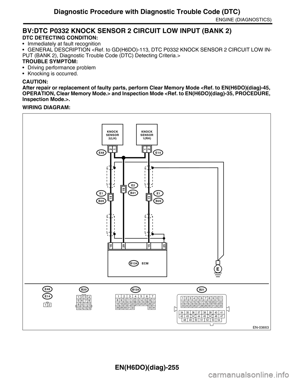
BV:DTC P0332 KNOCK SENSOR 2 CIRCUIT LOW INPUT (BANK 2)
DTC DETECTING CONDITION:
•Immediately at fault recognition
•GENERAL DESCRIPTION
TROUBLE SYMPTOM:
•Driving performance problem
•Knocking is occurred.
CAUTION:
After repair or replacement of faulty parts, perform Clear Memory Mode
WIRING DIAGRAM:
EN-03663
152925
KNOCKSENSOR1(RH)
13
21
ECMB134
B20
E1B21
E2
B20
E1
E14
12
16
KNOCKSENSOR2(LH)
1414
19
13
E48E14
E48B20
1234567891011 121314 15 16
E
B134
85610 11 12 13 14 157213416
3019 20 2228 29
91718252123 24323126 2733 34
B21
12345678910 1112 13 14 15 16 17 18 19 20 21 2223 24 25 26 27 28 29 30 31 32 33
34 3542 4336 3738 39
48 4950 5152 5354
40 41444546 47
21
Page 1417 of 2453
EN(H6DO)(diag)-256
Diagnostic Procedure with Diagnostic Trouble Code (DTC)
ENGINE (DIAGNOSTICS)
Step Check Yes No
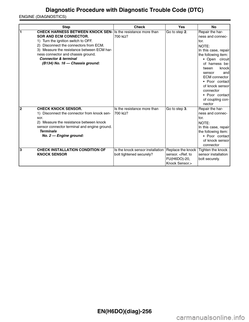
1CHECK HARNESS BETWEEN KNOCK SEN-
SOR AND ECM CONNECTOR.
1) Turn the ignition switch to OFF.
2) Disconnect the connectors from ECM.
3) Measure the resistance between ECM har-
ness connector and chassis ground.
Connector & terminal
(B134) No. 16 — Chassis ground:
Is the resistance more than
700 kΩ?
Go to step 2.Repair the har-
ness and connec-
tor.
NOTE:In this case, repair
the following item:
•Open circuit
of harness be-
tween knock
sensor and
ECM connector
•Poor contact
of knock sensor
connector
•Poor contact
of coupling con-
nector
2CHECK KNOCK SENSOR.
1) Disconnect the connector from knock sen-
sor.
2) Measure the resistance between knock
sensor connector terminal and engine ground.
Te r m i n a l s
No. 2 — Engine ground:
Is the resistance more than
700 kΩ?
Go to step 3.Repair the har-
ness and connec-
tor.
NOTE:In this case, repair
the following item:
•Poor contact
of knock sensor
connector
3CHECK INSTALLATION CONDITION OF
KNOCK SENSOR
Is the knock sensor installation
bolt tightened securely?
Replace the knock
sensor.
Knock Sensor.>
Tighten the knock
sensor installation
bolt securely.