sensor SUBARU TRIBECA 2009 1.G Service Workshop Manual
[x] Cancel search | Manufacturer: SUBARU, Model Year: 2009, Model line: TRIBECA, Model: SUBARU TRIBECA 2009 1.GPages: 2453, PDF Size: 46.32 MB
Page 1454 of 2453
EN(H6DO)(diag)-293
Diagnostic Procedure with Diagnostic Trouble Code (DTC)
ENGINE (DIAGNOSTICS)
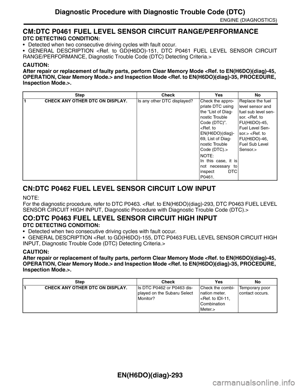
CM:DTC P0461 FUEL LEVEL SENSOR CIRCUIT RANGE/PERFORMANCE
DTC DETECTING CONDITION:
•Detected when two consecutive driving cycles with fault occur.
•GENERAL DESCRIPTION
CAUTION:
After repair or replacement of faulty parts, perform Clear Memory Mode
CN:DTC P0462 FUEL LEVEL SENSOR CIRCUIT LOW INPUT
NOTE:
For the diagnostic procedure, refer to DTC P0463.
CO:DTC P0463 FUEL LEVEL SENSOR CIRCUIT HIGH INPUT
DTC DETECTING CONDITION:
•Detected when two consecutive driving cycles with fault occur.
•GENERAL DESCRIPTION
CAUTION:
After repair or replacement of faulty parts, perform Clear Memory Mode
Step Check Yes No
1CHECK ANY OTHER DTC ON DISPLAY.Is any other DTC displayed? Check the appro-
priate DTC using
the “List of Diag-
nostic Trouble
Code (DTC)”.
69, List of Diag-
nostic Trouble
Code (DTC).>
NOTE:In this case, it is
not necessary to
inspect DTC
P0461.
Replace the fuel
level sensor and
fuel sub level sen-
sor.
Fuel Level Sen-
sor.>
Fuel Sub Level
Sensor.>
Step Check Yes No
1CHECK ANY OTHER DTC ON DISPLAY.Is DTC P0462 or P0463 dis-
played on the Subaru Select
Monitor?
Check the combi-
nation meter.
Meter.>
Te m p o r a r y p o o r
contact occurs.
Page 1455 of 2453
EN(H6DO)(diag)-294
Diagnostic Procedure with Diagnostic Trouble Code (DTC)
ENGINE (DIAGNOSTICS)
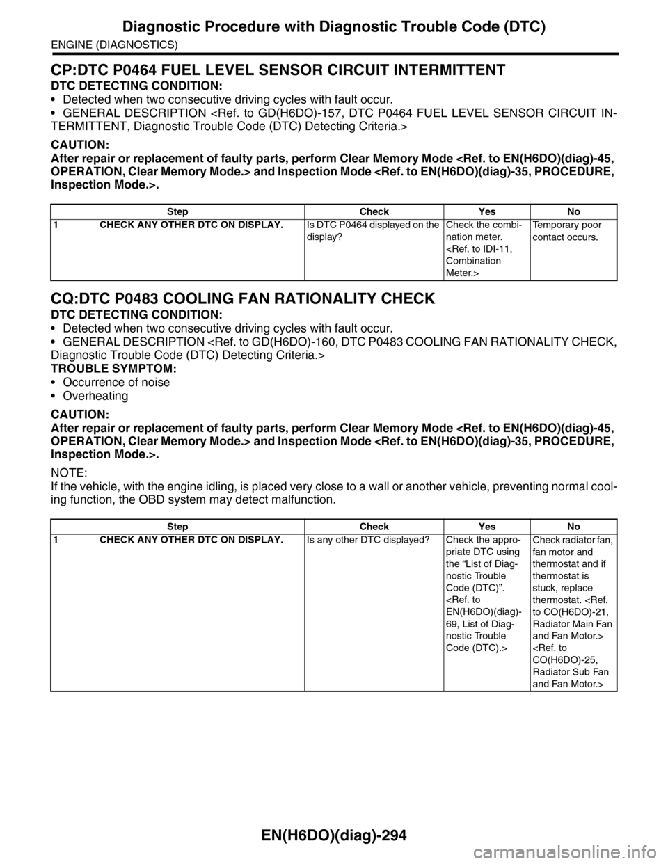
CP:DTC P0464 FUEL LEVEL SENSOR CIRCUIT INTERMITTENT
DTC DETECTING CONDITION:
•Detected when two consecutive driving cycles with fault occur.
•GENERAL DESCRIPTION
CAUTION:
After repair or replacement of faulty parts, perform Clear Memory Mode
CQ:DTC P0483 COOLING FAN RATIONALITY CHECK
DTC DETECTING CONDITION:
•Detected when two consecutive driving cycles with fault occur.
•GENERAL DESCRIPTION
TROUBLE SYMPTOM:
•Occurrence of noise
•Overheating
CAUTION:
After repair or replacement of faulty parts, perform Clear Memory Mode
NOTE:
If the vehicle, with the engine idling, is placed very close to a wall or another vehicle, preventing normal cool-
ing function, the OBD system may detect malfunction.
Step Check Yes No
1CHECK ANY OTHER DTC ON DISPLAY.Is DTC P0464 displayed on the
display?
Check the combi-
nation meter.
Meter.>
Te m p o r a r y p o o r
contact occurs.
Step Check Yes No
1CHECK ANY OTHER DTC ON DISPLAY.Is any other DTC displayed? Check the appro-
priate DTC using
the “List of Diag-
nostic Trouble
Code (DTC)”.
69, List of Diag-
nostic Trouble
Code (DTC).>
Check radiator fan,
fan motor and
thermostat and if
thermostat is
stuck, replace
thermostat.
Radiator Main Fan
and Fan Motor.>
Radiator Sub Fan
and Fan Motor.>
Page 1456 of 2453
EN(H6DO)(diag)-295
Diagnostic Procedure with Diagnostic Trouble Code (DTC)
ENGINE (DIAGNOSTICS)
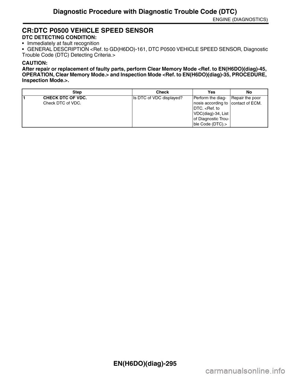
CR:DTC P0500 VEHICLE SPEED SENSOR
DTC DETECTING CONDITION:
•Immediately at fault recognition
•GENERAL DESCRIPTION
CAUTION:
After repair or replacement of faulty parts, perform Clear Memory Mode
Step Check Yes No
1CHECK DTC OF VDC.
Check DTC of VDC.
Is DTC of VDC displayed? Perform the diag-
nosis according to
DTC.
of Diagnostic Trou-
ble Code (DTC).>
Repair the poor
contact of ECM.
Page 1463 of 2453
EN(H6DO)(diag)-302
Diagnostic Procedure with Diagnostic Trouble Code (DTC)
ENGINE (DIAGNOSTICS)
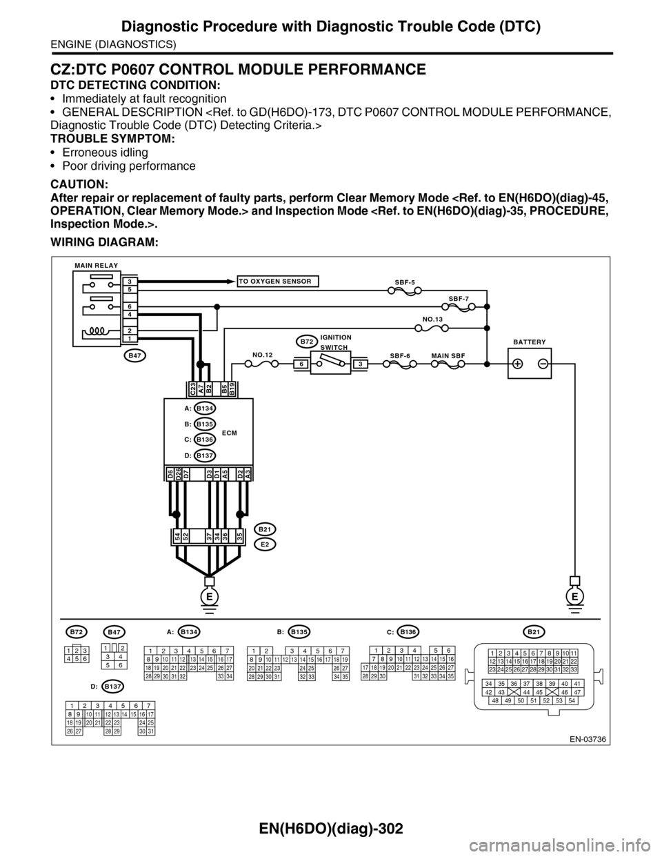
CZ:DTC P0607 CONTROL MODULE PERFORMANCE
DTC DETECTING CONDITION:
•Immediately at fault recognition
•GENERAL DESCRIPTION
TROUBLE SYMPTOM:
•Erroneous idling
•Poor driving performance
CAUTION:
After repair or replacement of faulty parts, perform Clear Memory Mode
WIRING DIAGRAM:
EN-03736
SBF-6MAIN SBF
SBF-7
B72
B2A7C23
D7D3D1A5
B5B19
NO.12B47
E2
B21
12
46
53
ECM
EE
36
B134A:
D:B137
B135B:
B136C:
A3
52373634
3412
56
B47
TO OXYGEN SENSOR
NO.13
D2
35
B21
123412131415567816171819910 1120212223 24 25 2627 28 29 3031 32 33
3534 37363938 41404342 4445 47464948 51505352 54
B72
134562
B134
56 7821943102422 23 2511 12 13 14 1526 2728
16 1718 19 20 2133 34293230 31
A:B135
567821943102422 23 2511 12 13 14 1526 2728
16 17 18 1920 2129 30 31 32 33 34 35
B:
B137
5678219431022 2311 12 13 14 1524 2526
16 1718 19 20 2127 28 29 30 31
D:
SBF-5
D6D26
54
MAIN RELAY
BATTERYIGNITIONSWITCH
B136
16101112131415252430
9871718192028212223293231
123456
2726333435
C:
Page 1465 of 2453
EN(H6DO)(diag)-304
Diagnostic Procedure with Diagnostic Trouble Code (DTC)
ENGINE (DIAGNOSTICS)
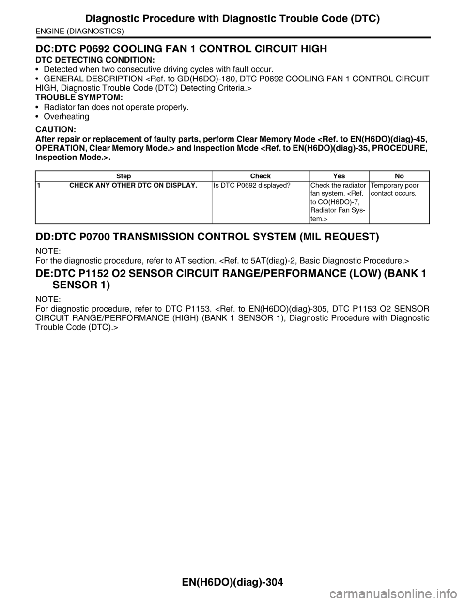
DC:DTC P0692 COOLING FAN 1 CONTROL CIRCUIT HIGH
DTC DETECTING CONDITION:
•Detected when two consecutive driving cycles with fault occur.
•GENERAL DESCRIPTION
TROUBLE SYMPTOM:
•Radiator fan does not operate properly.
•Overheating
CAUTION:
After repair or replacement of faulty parts, perform Clear Memory Mode
DD:DTC P0700 TRANSMISSION CONTROL SYSTEM (MIL REQUEST)
NOTE:
For the diagnostic procedure, refer to AT section.
DE:DTC P1152 O2 SENSOR CIRCUIT RANGE/PERFORMANCE (LOW) (BANK 1
SENSOR 1)
NOTE:
For diagnostic procedure, refer to DTC P1153.
Trouble Code (DTC).>
Step Check Yes No
1CHECK ANY OTHER DTC ON DISPLAY.Is DTC P0692 displayed? Check the radiator
fan system.
Radiator Fan Sys-
tem.>
Te m p o r a r y p o o r
contact occurs.
Page 1466 of 2453
EN(H6DO)(diag)-305
Diagnostic Procedure with Diagnostic Trouble Code (DTC)
ENGINE (DIAGNOSTICS)
DF:DTC P1153 O2 SENSOR CIRCUIT RANGE/PERFORMANCE (HIGH) (BANK 1
SENSOR 1)
DTC DETECTING CONDITION:
•Detected when two consecutive driving cycles with fault occur.
•GENERAL DESCRIPTION
CAUTION:
After repair or replacement of faulty parts, perform Clear Memory Mode
Page 1467 of 2453
EN(H6DO)(diag)-306
Diagnostic Procedure with Diagnostic Trouble Code (DTC)
ENGINE (DIAGNOSTICS)
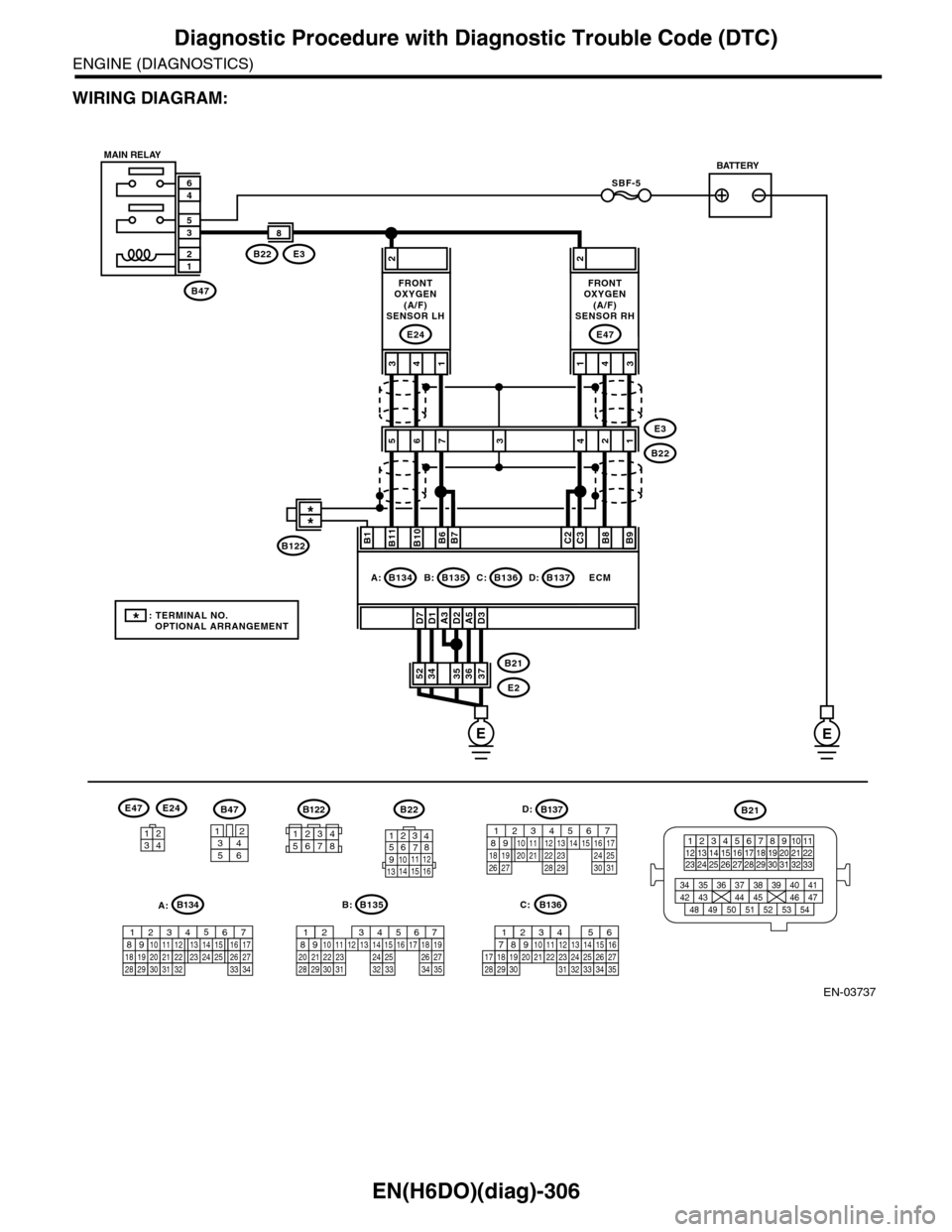
WIRING DIAGRAM:
EN-03737
SBF-5
B47
12
35
46
A3D1D7D2A5D3
2
3736353452B21
E2
ECM
B11B1B10B6B7C2C3B8B9
413
E24
2
431
E47
E3B22
8
56E3
B222134
B47
3456
12
B22
1234567891011 121314 15 16
3412
E47E24
B135
567821943102422 23 2511 12 13 14 1526 2728
16 17 18 1920 2129 30 31 32 33 34 35
B:
B21
123412131415567816171819910 1120212223 24 25 2627 28 29 3031 32 33
3534 37363938 41404342 4445 47464948 51505352 54
EE
B135B:B136C:B137D:B134A:
7
FRONTOXYGEN(A/F)SENSOR LH
FRONTOXYGEN(A/F)SENSOR RH
MAIN RELAYBATTERY
B136
16101112131415252430
9871718192028212223293231
123456
2726333435
C:
B137
85610 11 12 13 14 157213416
3019 20 2228 29
91718 2521 23 243126 27
D:B122
34561278
*: TERMINAL NO. OPTIONAL ARRANGEMENT
**
B122
A:B134
85610 11 12 13 14 157213416
3019 20 2228 29
91718252123 24323126 2733 34
Page 1468 of 2453
EN(H6DO)(diag)-307
Diagnostic Procedure with Diagnostic Trouble Code (DTC)
ENGINE (DIAGNOSTICS)
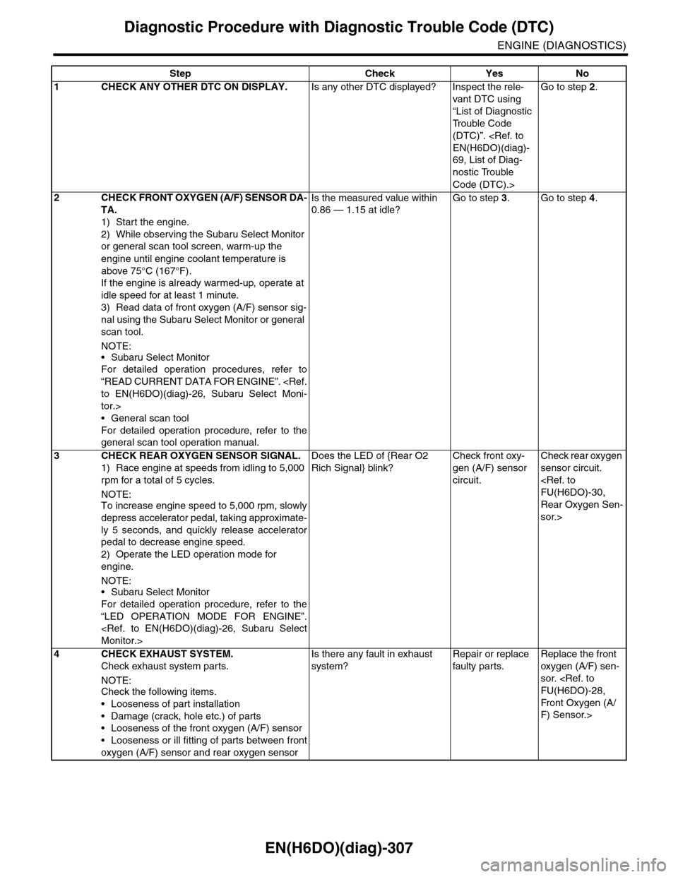
Step Check Yes No
1CHECK ANY OTHER DTC ON DISPLAY.Is any other DTC displayed? Inspect the rele-
vant DTC using
“List of Diagnostic
Tr o u b l e C o d e
(DTC)”.
69, List of Diag-
nostic Trouble
Code (DTC).>
Go to step 2.
2CHECK FRONT OXYGEN (A/F) SENSOR DA-
TA.
1) Start the engine.
2) While observing the Subaru Select Monitor
or general scan tool screen, warm-up the
engine until engine coolant temperature is
above 75°C (167°F).
If the engine is already warmed-up, operate at
idle speed for at least 1 minute.
3) Read data of front oxygen (A/F) sensor sig-
nal using the Subaru Select Monitor or general
scan tool.
NOTE:
•Subaru Select Monitor
For detailed operation procedures, refer to
“READ CURRENT DATA FOR ENGINE”.
tor.>
•General scan tool
For detailed operation procedure, refer to the
general scan tool operation manual.
Is the measured value within
0.86 — 1.15 at idle?
Go to step 3.Go to step 4.
3CHECK REAR OXYGEN SENSOR SIGNAL.
1) Race engine at speeds from idling to 5,000
rpm for a total of 5 cycles.
NOTE:To increase engine speed to 5,000 rpm, slowly
depress accelerator pedal, taking approximate-
ly 5 seconds, and quickly release accelerator
pedal to decrease engine speed.
2) Operate the LED operation mode for
engine.
NOTE:•Subaru Select Monitor
For detailed operation procedure, refer to the
“LED OPERATION MODE FOR ENGINE”.
Does the LED of {Rear O2
Rich Signal} blink?
Check front oxy-
gen (A/F) sensor
circuit.
Check rear oxygen
sensor circuit.
Rear Oxygen Sen-
sor.>
4 CHECK EXHAUST SYSTEM.
Check exhaust system parts.
NOTE:Check the following items.
•Looseness of part installation
•Damage (crack, hole etc.) of parts
•Looseness of the front oxygen (A/F) sensor
•Looseness or ill fitting of parts between front
oxygen (A/F) sensor and rear oxygen sensor
Is there any fault in exhaust
system?
Repair or replace
faulty par ts.
Replace the front
oxygen (A/F) sen-
sor.
Fr o nt Ox yg en ( A /
F) Sensor.>
Page 1469 of 2453
EN(H6DO)(diag)-308
Diagnostic Procedure with Diagnostic Trouble Code (DTC)
ENGINE (DIAGNOSTICS)
DG:DTC P1154 O2 SENSOR CIRCUIT RANGE/PERFORMANCE (LOW) (BANK 2
SENSOR 1)
NOTE:
For diagnostic procedure, refer to DTC P1155.
Trouble Code (DTC).>
Page 1470 of 2453
EN(H6DO)(diag)-309
Diagnostic Procedure with Diagnostic Trouble Code (DTC)
ENGINE (DIAGNOSTICS)
DH:DTC P1155 O2 SENSOR CIRCUIT RANGE/PERFORMANCE (HIGH) (BANK 2
SENSOR 1)
DTC DETECTING CONDITION:
•Detected when two consecutive driving cycles with fault occur.
•GENERAL DESCRIPTION
CAUTION:
After repair or replacement of faulty parts, perform Clear Memory Mode