check engine light SUBARU TRIBECA 2009 1.G Service Repair Manual
[x] Cancel search | Manufacturer: SUBARU, Model Year: 2009, Model line: TRIBECA, Model: SUBARU TRIBECA 2009 1.GPages: 2453, PDF Size: 46.32 MB
Page 1437 of 2453
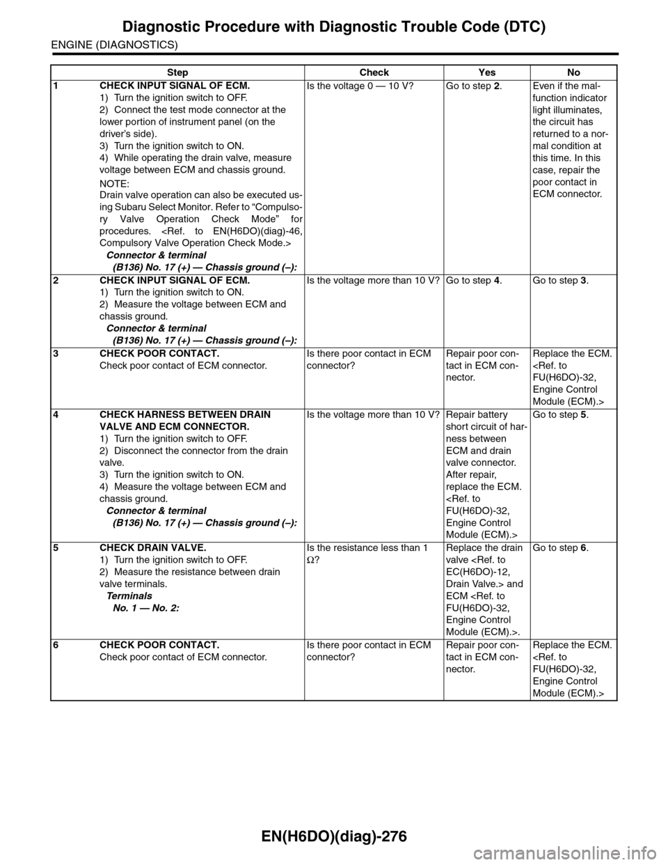
EN(H6DO)(diag)-276
Diagnostic Procedure with Diagnostic Trouble Code (DTC)
ENGINE (DIAGNOSTICS)
Step Check Yes No
1CHECK INPUT SIGNAL OF ECM.
1) Turn the ignition switch to OFF.
2) Connect the test mode connector at the
lower portion of instrument panel (on the
driver’s side).
3) Turn the ignition switch to ON.
4) While operating the drain valve, measure
voltage between ECM and chassis ground.
NOTE:
Drain valve operation can also be executed us-
ing Subaru Select Monitor. Refer to “Compulso-
ry Valve Operation Check Mode” for
procedures.
Connector & terminal
(B136) No. 17 (+) — Chassis ground (–):
Is the voltage 0 — 10 V? Go to step 2.Even if the mal-
function indicator
light illuminates,
the circuit has
returned to a nor-
mal condition at
this time. In this
case, repair the
poor contact in
ECM connector.
2CHECK INPUT SIGNAL OF ECM.
1) Turn the ignition switch to ON.
2) Measure the voltage between ECM and
chassis ground.
Connector & terminal
(B136) No. 17 (+) — Chassis ground (–):
Is the voltage more than 10 V? Go to step 4.Go to step 3.
3CHECK POOR CONTACT.
Check poor contact of ECM connector.
Is there poor contact in ECM
connector?
Repair poor con-
tact in ECM con-
nector.
Replace the ECM.
Engine Control
Module (ECM).>
4CHECK HARNESS BETWEEN DRAIN
VALVE AND ECM CONNECTOR.
1) Turn the ignition switch to OFF.
2) Disconnect the connector from the drain
valve.
3) Turn the ignition switch to ON.
4) Measure the voltage between ECM and
chassis ground.
Connector & terminal
(B136) No. 17 (+) — Chassis ground (–):
Is the voltage more than 10 V? Repair battery
short circuit of har-
ness between
ECM and drain
valve connector.
After repair,
replace the ECM.
Engine Control
Module (ECM).>
Go to step 5.
5CHECK DRAIN VALVE.
1) Turn the ignition switch to OFF.
2) Measure the resistance between drain
valve terminals.
Te r m i n a l s
No. 1 — No. 2:
Is the resistance less than 1
Ω?
Replace the drain
valve
Drain Valve.> and
ECM
Engine Control
Module (ECM).>.
Go to step 6.
6CHECK POOR CONTACT.
Check poor contact of ECM connector.
Is there poor contact in ECM
connector?
Repair poor con-
tact in ECM con-
nector.
Replace the ECM.
Engine Control
Module (ECM).>
Page 1441 of 2453
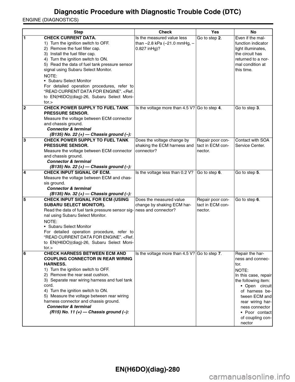
EN(H6DO)(diag)-280
Diagnostic Procedure with Diagnostic Trouble Code (DTC)
ENGINE (DIAGNOSTICS)
Step Check Yes No
1CHECK CURRENT DATA.
1) Turn the ignition switch to OFF.
2) Remove the fuel filler cap.
3) Install the fuel filler cap.
4) Turn the ignition switch to ON.
5) Read the data of fuel tank pressure sensor
signal using Subaru Select Monitor.
NOTE:•Subaru Select Monitor
For detailed operation procedures, refer to
“READ CURRENT DATA FOR ENGINE”.
tor.>
Is the measured value less
than –2.8 kPa (–21.0 mmHg, –
0.827 inHg)?
Go to step 2.Even if the mal-
function indicator
light illuminates,
the circuit has
returned to a nor-
mal condition at
this time.
2CHECK POWER SUPPLY TO FUEL TANK
PRESSURE SENSOR.
Measure the voltage between ECM connector
and chassis ground.
Connector & terminal
(B135) No. 22 (+) — Chassis ground (–):
Is the voltage more than 4.5 V? Go to step 4.Go to step 3.
3CHECK POWER SUPPLY TO FUEL TANK
PRESSURE SENSOR.
Measure the voltage between ECM connector
and chassis ground.
Connector & terminal
(B135) No. 22 (+) — Chassis ground (–):
Does the voltage change by
shaking the ECM harness and
connector?
Repair poor con-
tact in ECM con-
nector.
Contact with SOA
Service Center.
4CHECK INPUT SIGNAL OF ECM.
Measure the voltage between ECM and chas-
sis ground.
Connector & terminal
(B135) No. 32 (+) — Chassis ground (–):
Is the voltage less than 0.2 V? Go to step 6.Go to step 5.
5CHECK INPUT SIGNAL FOR ECM (USING
SUBARU SELECT MONITOR).
Read the data of fuel tank pressure sensor sig-
nal using Subaru Select Monitor.
NOTE:
•Subaru Select Monitor
For detailed operation procedure, refer to
“READ CURRENT DATA FOR ENGINE”.
tor.>
Does the measured value
change by shaking ECM har-
ness and connector?
Repair poor con-
tact in ECM con-
nector.
Go to step 6.
6CHECK HARNESS BETWEEN ECM AND
COUPLING CONNECTOR IN REAR WIRING
HARNESS.
1) Turn the ignition switch to OFF.
2) Remove the rear seat cushion.
3) Separate rear wiring harness and fuel tank
cord.
4) Turn the ignition switch to ON.
5) Measure the voltage between rear wiring
harness connector and chassis ground.
Connector & terminal
(R15) No. 11 (+) — Chassis ground (–):
Is the voltage more than 4.5 V? Go to step 7.Repair the har-
ness and connec-
tor.
NOTE:In this case, repair
the following item:
•Open circuit
of harness be-
tween ECM and
rear wiring har-
ness connector
•Poor contact
of coupling con-
nector
Page 1451 of 2453
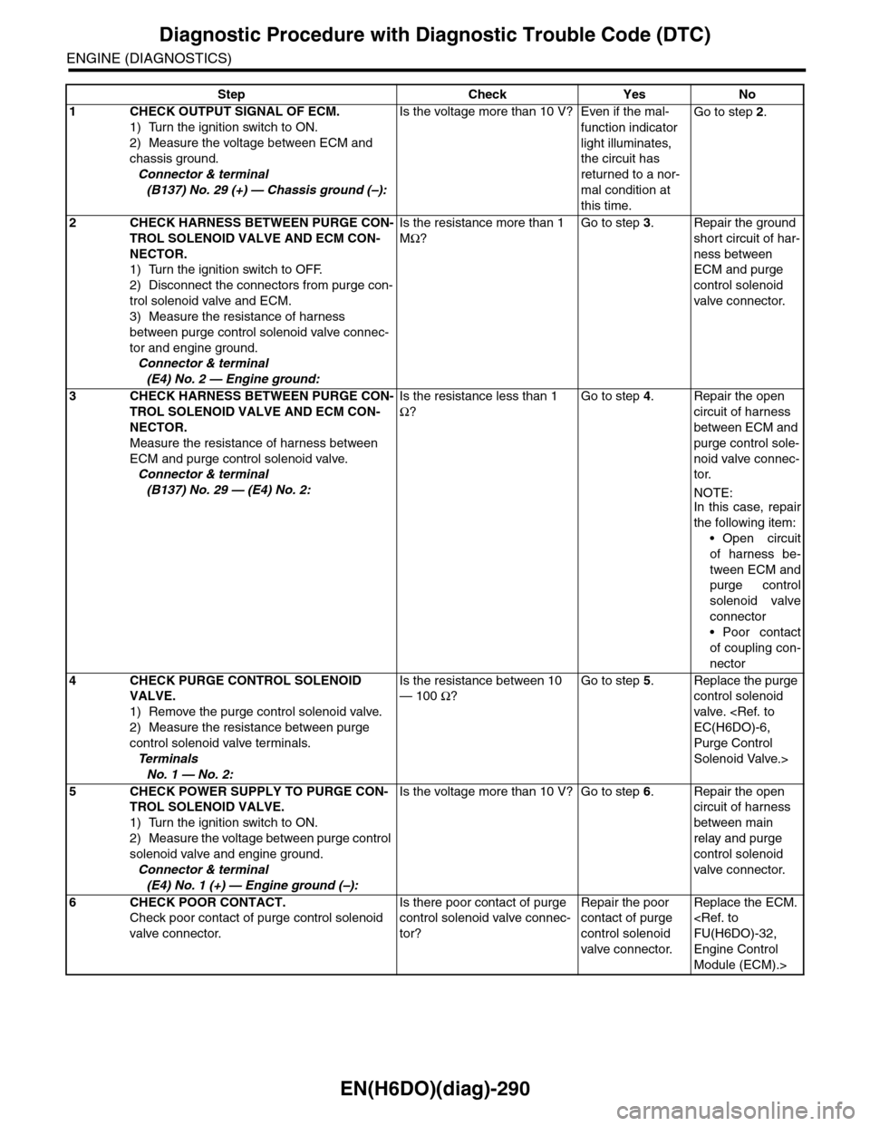
EN(H6DO)(diag)-290
Diagnostic Procedure with Diagnostic Trouble Code (DTC)
ENGINE (DIAGNOSTICS)
Step Check Yes No
1CHECK OUTPUT SIGNAL OF ECM.
1) Turn the ignition switch to ON.
2) Measure the voltage between ECM and
chassis ground.
Connector & terminal
(B137) No. 29 (+) — Chassis ground (–):
Is the voltage more than 10 V? Even if the mal-
function indicator
light illuminates,
the circuit has
returned to a nor-
mal condition at
this time.
Go to step 2.
2CHECK HARNESS BETWEEN PURGE CON-
TROL SOLENOID VALVE AND ECM CON-
NECTOR.
1) Turn the ignition switch to OFF.
2) Disconnect the connectors from purge con-
trol solenoid valve and ECM.
3) Measure the resistance of harness
between purge control solenoid valve connec-
tor and engine ground.
Connector & terminal
(E4) No. 2 — Engine ground:
Is the resistance more than 1
MΩ?
Go to step 3.Repair the ground
short circuit of har-
ness between
ECM and purge
control solenoid
valve connector.
3CHECK HARNESS BETWEEN PURGE CON-
TROL SOLENOID VALVE AND ECM CON-
NECTOR.
Measure the resistance of harness between
ECM and purge control solenoid valve.
Connector & terminal
(B137) No. 29 — (E4) No. 2:
Is the resistance less than 1
Ω?
Go to step 4.Repair the open
circuit of harness
between ECM and
purge control sole-
noid valve connec-
tor.
NOTE:In this case, repair
the following item:
•Open circuit
of harness be-
tween ECM and
purge control
solenoid valve
connector
•Poor contact
of coupling con-
nector
4CHECK PURGE CONTROL SOLENOID
VALVE.
1) Remove the purge control solenoid valve.
2) Measure the resistance between purge
control solenoid valve terminals.
Te r m i n a l s
No. 1 — No. 2:
Is the resistance between 10
— 100 Ω?
Go to step 5.Replace the purge
control solenoid
valve.
Purge Control
Solenoid Valve.>
5CHECK POWER SUPPLY TO PURGE CON-
TROL SOLENOID VALVE.
1) Turn the ignition switch to ON.
2) Measure the voltage between purge control
solenoid valve and engine ground.
Connector & terminal
(E4) No. 1 (+) — Engine ground (–):
Is the voltage more than 10 V? Go to step 6.Repair the open
circuit of harness
between main
relay and purge
control solenoid
valve connector.
6CHECK POOR CONTACT.
Check poor contact of purge control solenoid
valve connector.
Is there poor contact of purge
control solenoid valve connec-
tor?
Repair the poor
contact of purge
control solenoid
valve connector.
Replace the ECM.
Engine Control
Module (ECM).>
Page 1453 of 2453
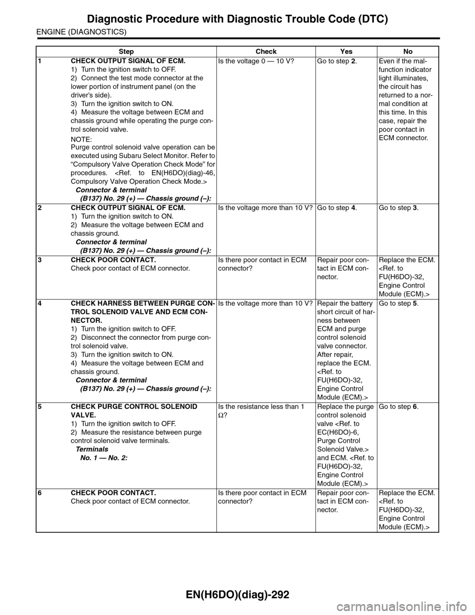
EN(H6DO)(diag)-292
Diagnostic Procedure with Diagnostic Trouble Code (DTC)
ENGINE (DIAGNOSTICS)
Step Check Yes No
1CHECK OUTPUT SIGNAL OF ECM.
1) Turn the ignition switch to OFF.
2) Connect the test mode connector at the
lower portion of instrument panel (on the
driver’s side).
3) Turn the ignition switch to ON.
4) Measure the voltage between ECM and
chassis ground while operating the purge con-
trol solenoid valve.
NOTE:Purge control solenoid valve operation can be
executed using Subaru Select Monitor. Refer to
“Compulsory Valve Operation Check Mode” for
procedures.
Connector & terminal
(B137) No. 29 (+) — Chassis ground (–):
Is the voltage 0 — 10 V? Go to step 2.Even if the mal-
function indicator
light illuminates,
the circuit has
returned to a nor-
mal condition at
this time. In this
case, repair the
poor contact in
ECM connector.
2CHECK OUTPUT SIGNAL OF ECM.
1) Turn the ignition switch to ON.
2) Measure the voltage between ECM and
chassis ground.
Connector & terminal
(B137) No. 29 (+) — Chassis ground (–):
Is the voltage more than 10 V? Go to step 4.Go to step 3.
3CHECK POOR CONTACT.
Check poor contact of ECM connector.
Is there poor contact in ECM
connector?
Repair poor con-
tact in ECM con-
nector.
Replace the ECM.
Engine Control
Module (ECM).>
4CHECK HARNESS BETWEEN PURGE CON-
TROL SOLENOID VALVE AND ECM CON-
NECTOR.
1) Turn the ignition switch to OFF.
2) Disconnect the connector from purge con-
trol solenoid valve.
3) Turn the ignition switch to ON.
4) Measure the voltage between ECM and
chassis ground.
Connector & terminal
(B137) No. 29 (+) — Chassis ground (–):
Is the voltage more than 10 V? Repair the battery
short circuit of har-
ness between
ECM and purge
control solenoid
valve connector.
After repair,
replace the ECM.
Engine Control
Module (ECM).>
Go to step 5.
5CHECK PURGE CONTROL SOLENOID
VALVE.
1) Turn the ignition switch to OFF.
2) Measure the resistance between purge
control solenoid valve terminals.
Te r m i n a l s
No. 1 — No. 2:
Is the resistance less than 1
Ω?
Replace the purge
control solenoid
valve
Purge Control
Solenoid Valve.>
and ECM.
Engine Control
Module (ECM).>
Go to step 6.
6CHECK POOR CONTACT.
Check poor contact of ECM connector.
Is there poor contact in ECM
connector?
Repair poor con-
tact in ECM con-
nector.
Replace the ECM.
Engine Control
Module (ECM).>
Page 1772 of 2453
GD(H6DO)-160
Diagnostic Trouble Code (DTC) Detecting Criteria
GENERAL DESCRIPTION
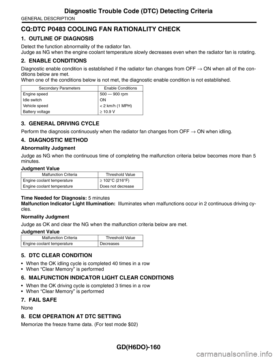
CQ:DTC P0483 COOLING FAN RATIONALITY CHECK
1. OUTLINE OF DIAGNOSIS
Detect the function abnormality of the radiator fan.
Judge as NG when the engine coolant temperature slowly decreases even when the radiator fan is rotating.
2. ENABLE CONDITIONS
Diagnostic enable condition is established if the radiator fan changes from OFF → ON when all of the con-
ditions below are met.
When one of the conditions below is not met, the diagnostic enable condition is not established.
3. GENERAL DRIVING CYCLE
Perform the diagnosis continuously when the radiator fan changes from OFF → ON when idling.
4. DIAGNOSTIC METHOD
Abnormality Judgment
Judge as NG when the continuous time of completing the malfunction criteria below becomes more than 5
minutes.
Time Needed for Diagnosis: 5 minutes
Malfunction Indicator Light Illumination: Illuminates when malfunctions occur in 2 continuous driving cy-
cles.
Normality Judgment
Judge as OK and clear the NG when the malfunction criteria below are met.
5. DTC CLEAR CONDITION
•When the OK idling cycle is completed 40 times in a row
•When “Clear Memory” is performed
6. MALFUNCTION INDICATOR LIGHT CLEAR CONDITIONS
•When the OK driving cycle is completed 3 times in a row
•When “Clear Memory” is performed
7. FAIL SAFE
None
8. ECM OPERATION AT DTC SETTING
Memorize the freeze frame data. (For test mode $02)
Secondary Parameters Enable Conditions
Engine speed 500 — 900 rpm
Idle switch ON
Ve h i c l e s p e e d < 2 k m / h ( 1 M P H )
Battery voltage≥ 10.9 V
Judgment Value
Malfunction Criteria Threshold Value
Engine coolant temperature≥ 102°C (216°F)
Engine coolant temperature Does not decrease
Judgment Value
Malfunction Criteria Threshold Value
Engine coolant temperature Decreases
Page 1855 of 2453
LU(H6DO)-6
Oil Pressure System
LUBRICATION
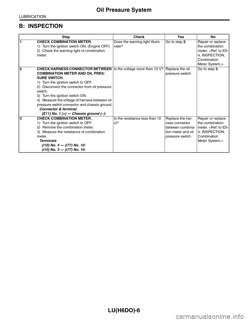
B: INSPECTION
Step Check Yes No
1CHECK COMBINATION METER.
1) Turn the ignition switch ON. (Engine OFF)
2) Check the warning light of combination
meter.
Does the warning light illumi-
nate?
Go to step 2.Repair or replace
the combination
meter.
Combination
Meter System.>
2CHECK HARNESS CONNECTOR BETWEEN
COMBINATION METER AND OIL PRES-
SURE SWITCH.
1) Turn the ignition switch to OFF.
2) Disconnect the connector from oil pressure
switch.
3) Turn the ignition switch ON.
4) Measure the voltage of harness between oil
pressure switch connector and chassis ground.
Connector & terminal
(E11) No. 1 (+) — Chassis ground (–):
Is the voltage more than 10 V? Replace the oil
pressure switch.
Go to step 3.
3CHECK COMBINATION METER.
1) Turn the ignition switch to OFF.
2) Remove the combination meter.
3) Measure the resistance of combination
meter.
Te r m i n a l s
(i10) No. 4 — (i77) No. 10:
(i10) No. 3 — (i77) No. 10:
Is the resistance less than 10
Ω?
Replace the har-
ness connector
between combina-
tion meter and oil
pressure switch.
Repair or replace
the combination
meter.
Combination
Meter System.>
Page 1866 of 2453
LU(H6DO)-17
General Diagnostics Table
LUBRICATION
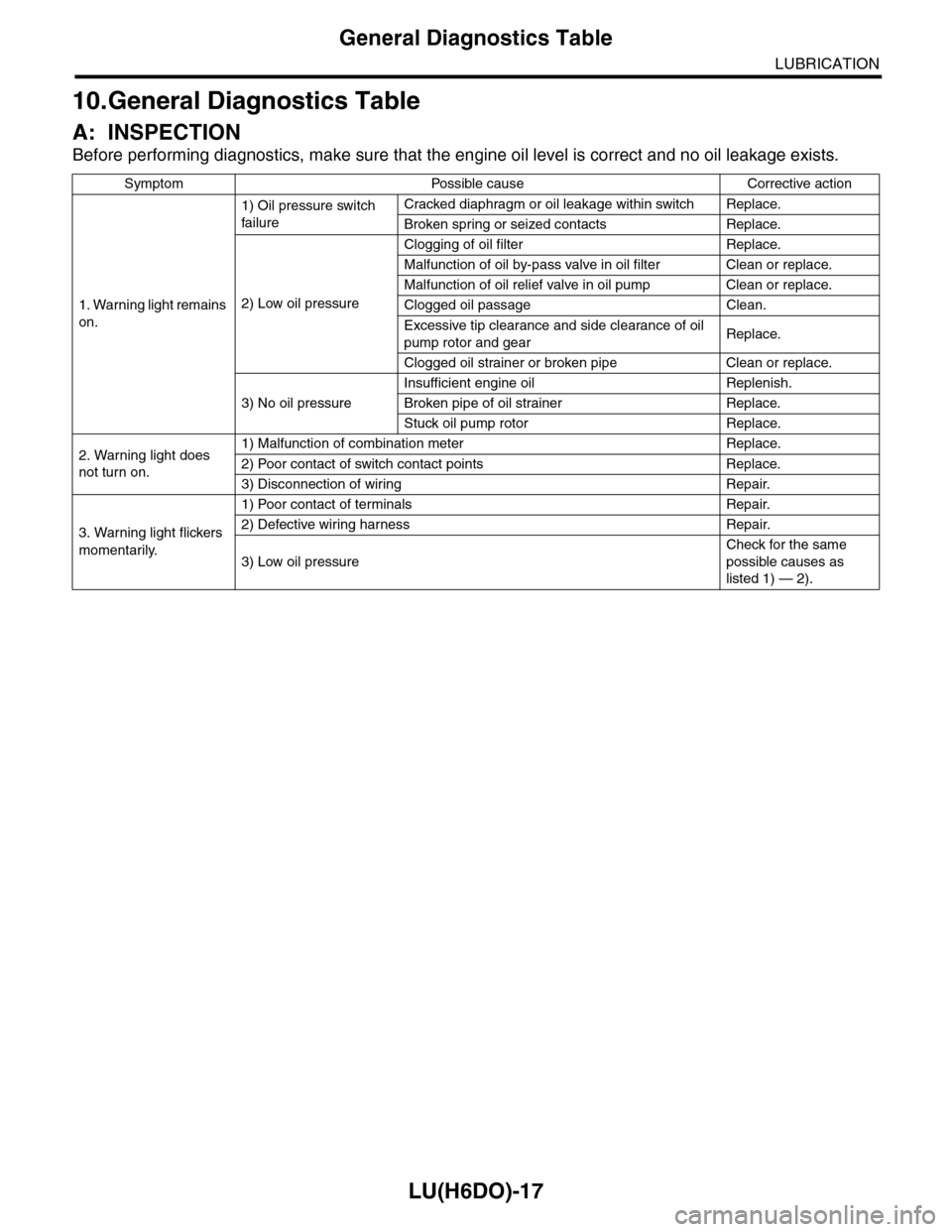
10.General Diagnostics Table
A: INSPECTION
Before performing diagnostics, make sure that the engine oil level is correct and no oil leakage exists.
Symptom Possible cause Corrective action
1. Warning light remains
on.
1) Oil pressure switch
failure
Cracked diaphragm or oil leakage within switch Replace.
Broken spring or seized contacts Replace.
2) Low oil pressure
Clogging of oil filter Replace.
Malfunction of oil by-pass valve in oil filter Clean or replace.
Malfunction of oil relief valve in oil pump Clean or replace.
Clogged oil passage Clean.
Excessive tip clearance and side clearance of oil
pump rotor and gearReplace.
Clogged oil strainer or broken pipe Clean or replace.
3) No oil pressure
Insufficient engine oil Replenish.
Broken pipe of oil strainer Replace.
Stuck oil pump rotor Replace.
2. Warning light does
not turn on.
1) Malfunction of combination meter Replace.
2) Poor contact of switch contact points Replace.
3) Disconnection of wiring Repair.
3. Warning light flickers
momentarily.
1) Poor contact of terminals Repair.
2) Defective wiring harness Repair.
3) Low oil pressure
Check for the same
possible causes as
listed 1) — 2).
Page 1888 of 2453
ME(H6DO)-22
Idle Speed
MECHANICAL
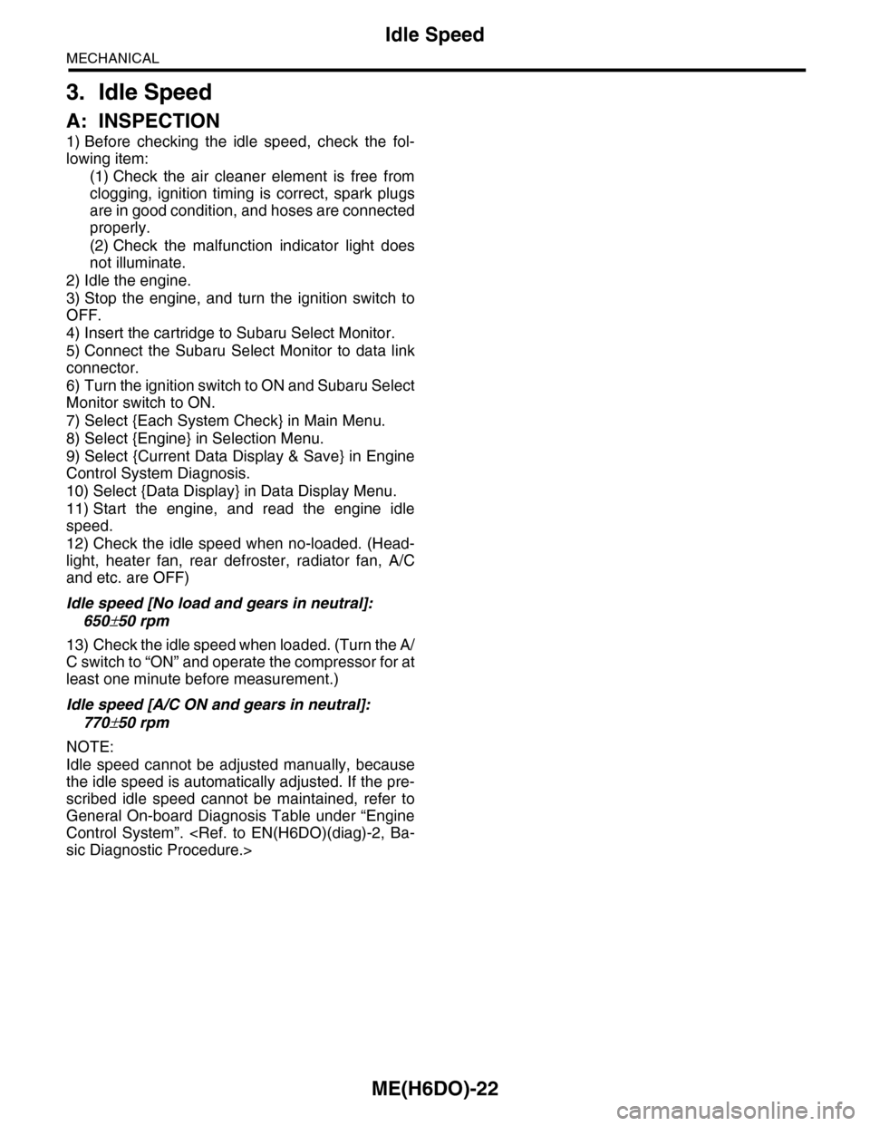
3. Idle Speed
A: INSPECTION
1) Before checking the idle speed, check the fol-
lowing item:
(1) Check the air cleaner element is free from
clogging, ignition timing is correct, spark plugs
are in good condition, and hoses are connected
properly.
(2) Check the malfunction indicator light does
not illuminate.
2) Idle the engine.
3) Stop the engine, and turn the ignition switch to
OFF.
4) Insert the cartridge to Subaru Select Monitor.
5) Connect the Subaru Select Monitor to data link
connector.
6) Turn the ignition switch to ON and Subaru Select
Monitor switch to ON.
7) Select {Each System Check} in Main Menu.
8) Select {Engine} in Selection Menu.
9) Select {Current Data Display & Save} in Engine
Control System Diagnosis.
10) Select {Data Display} in Data Display Menu.
11) Start the engine, and read the engine idle
speed.
12) Check the idle speed when no-loaded. (Head-
light, heater fan, rear defroster, radiator fan, A/C
and etc. are OFF)
Idle speed [No load and gears in neutral]:
650±50 rpm
13) Check the idle speed when loaded. (Turn the A/
C switch to “ON” and operate the compressor for at
least one minute before measurement.)
Idle speed [A/C ON and gears in neutral]:
770±50 rpm
NOTE:
Idle speed cannot be adjusted manually, because
the idle speed is automatically adjusted. If the pre-
scribed idle speed cannot be maintained, refer to
General On-board Diagnosis Table under “Engine
Control System”.
Page 1889 of 2453
ME(H6DO)-23
Ignition Timing
MECHANICAL
4. Ignition Timing
A: INSPECTION
CAUTION:
After warming-up, engine becomes very hot. Be
careful not to burn yourself at measurement.
1) Before checking the ignition timing, check the
following item:
(1) Check the air cleaner element is free from
clogging, spark plugs are in good condition, and
hoses are connected properly.
(2) Check the malfunction indicator light does
not illuminate.
2) Idle the engine.
3) Stop the engine, and turn the ignition switch to
OFF.
4) Insert the cartridge to Subaru Select Monitor.
5) Connect the Subaru Select Monitor to data link
connector.
6) Turn the ignition switch to ON and Subaru Select
Monitor switch to ON.
7) Select {Each System Check} in Main Menu.
8) Select {Engine} in Selection Menu.
9) Select {Current Data Display & Save} in Engine
Control System Diagnosis.
10) Select {Data Display} in Data Display Menu.
11) Start the engine and check the ignition timing at
idle speed.
Ignition timing [BTDC/rpm]:
15°±8°/650
If the timing is not correct, check the ignition control
system. Refer to Engine Control System.
Page 1891 of 2453
ME(H6DO)-25
Engine Oil Pressure
MECHANICAL
6. Engine Oil Pressure
A: INSPECTION
1) Remove the oil pressure switch from cylinder
block.
2) Connect the oil pressure gauge hose to cylinder
block.
3) Connect the ground cable to the battery.
4) Start the engine, and measure the oil pressure.
OIL PRESSURE (at oil temperature of 80°C
(176°F)):
Standard:
135 kPa (1.4 kgf/cm2, 20 psi) or more (at
600 rpm)
500 kPa (5.1 kgf/cm2, 73 psi) or more (at
5,000 rpm)
CAUTION:
•If the oil pressure is out of specification,
check oil pump, oil filter and lubrication line.
•If the oil pressure warning light is turned ON
and oil pressure is in specification, replace the
oil pressure switch.
5) After measuring the oil pressure, install the oil
pressure switch.
Tightening torque:
25 N·m (2.5 kgf-m, 18 ft-lb)