sensor SUBARU TRIBECA 2009 1.G Service Workshop Manual
[x] Cancel search | Manufacturer: SUBARU, Model Year: 2009, Model line: TRIBECA, Model: SUBARU TRIBECA 2009 1.GPages: 2453, PDF Size: 46.32 MB
Page 2163 of 2453
5AT(diag)-46
Diagnostic Procedure with Diagnostic Trouble Code (DTC)
AUTOMATIC TRANSMISSION (DIAGNOSTICS)
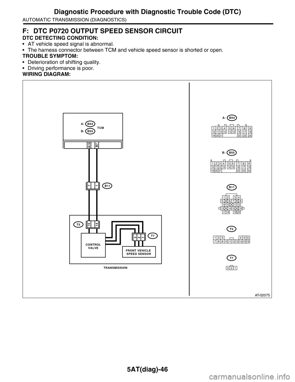
F: DTC P0720 OUTPUT SPEED SENSOR CIRCUIT
DTC DETECTING CONDITION:
•AT vehicle speed signal is abnormal.
•The harness connector between TCM and vehicle speed sensor is shorted or open.
TROUBLE SYMPTOM:
•Deterioration of shifting quality.
•Driving performance is poor.
WIRING DIAGRAM:
AT-02075
T7
321
TCM
TRANSMISSION
FRONT VEHICLE SPEED SENSOR
B55B:
B54A:
B11
B7A16
12341011 121920 21135614 1578916 17 1822 23 24
B55
B11
125678
131415169101112
34
17181920
B54
12789563410 11 1219 20 2113 14 15 16 17 18222324
A:
B:
T51415
123 68910 11 12 13 14451516
T5
7
17
321
CONTROLVALVE
T7
Page 2164 of 2453
5AT(diag)-47
Diagnostic Procedure with Diagnostic Trouble Code (DTC)
AUTOMATIC TRANSMISSION (DIAGNOSTICS)
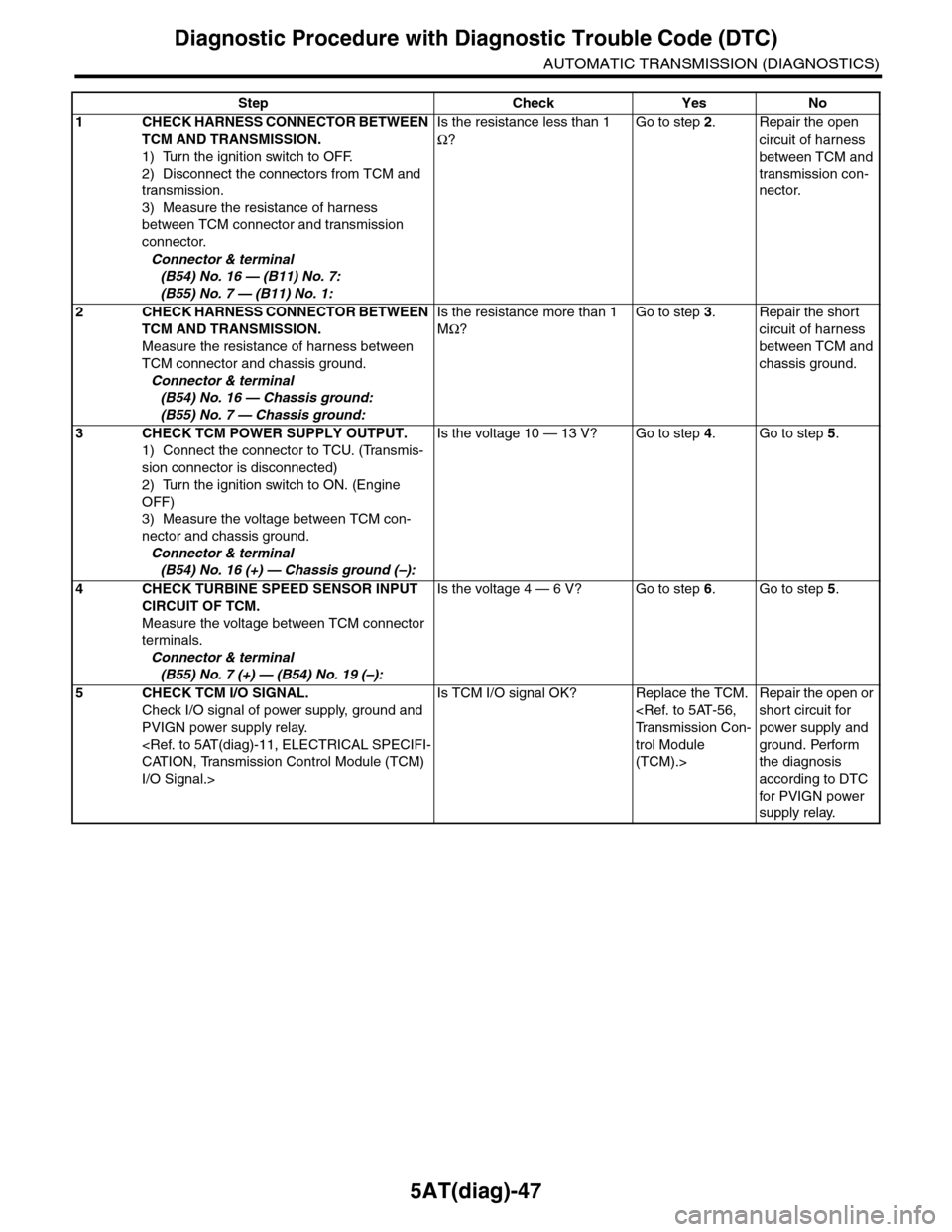
Step Check Yes No
1CHECK HARNESS CONNECTOR BETWEEN
TCM AND TRANSMISSION.
1) Turn the ignition switch to OFF.
2) Disconnect the connectors from TCM and
transmission.
3) Measure the resistance of harness
between TCM connector and transmission
connector.
Connector & terminal
(B54) No. 16 — (B11) No. 7:
(B55) No. 7 — (B11) No. 1:
Is the resistance less than 1
Ω?
Go to step 2.Repair the open
circuit of harness
between TCM and
transmission con-
nector.
2CHECK HARNESS CONNECTOR BETWEEN
TCM AND TRANSMISSION.
Measure the resistance of harness between
TCM connector and chassis ground.
Connector & terminal
(B54) No. 16 — Chassis ground:
(B55) No. 7 — Chassis ground:
Is the resistance more than 1
MΩ?
Go to step 3.Repair the short
circuit of harness
between TCM and
chassis ground.
3CHECK TCM POWER SUPPLY OUTPUT.
1) Connect the connector to TCU. (Transmis-
sion connector is disconnected)
2) Turn the ignition switch to ON. (Engine
OFF)
3) Measure the voltage between TCM con-
nector and chassis ground.
Connector & terminal
(B54) No. 16 (+) — Chassis ground (–):
Is the voltage 10 — 13 V? Go to step 4.Go to step 5.
4CHECK TURBINE SPEED SENSOR INPUT
CIRCUIT OF TCM.
Measure the voltage between TCM connector
terminals.
Connector & terminal
(B55) No. 7 (+) — (B54) No. 19 (–):
Is the voltage 4 — 6 V? Go to step 6.Go to step 5.
5CHECK TCM I/O SIGNAL.
Check I/O signal of power supply, ground and
PVIGN power supply relay.
I/O Signal.>
Is TCM I/O signal OK? Replace the TCM.
trol Module
(TCM).>
Repair the open or
short circuit for
power supply and
ground. Perform
the diagnosis
according to DTC
for PVIGN power
supply relay.
Page 2165 of 2453
5AT(diag)-48
Diagnostic Procedure with Diagnostic Trouble Code (DTC)
AUTOMATIC TRANSMISSION (DIAGNOSTICS)
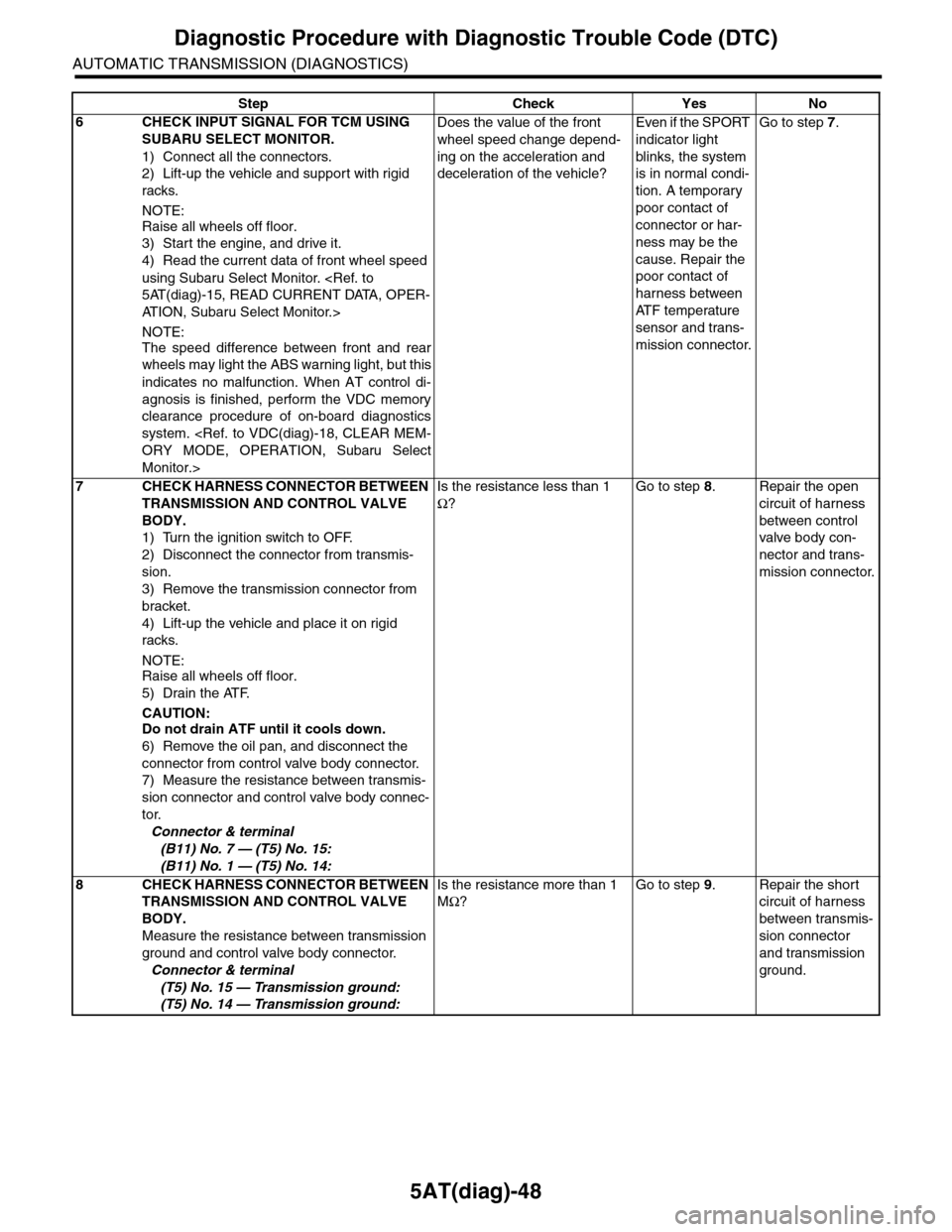
6CHECK INPUT SIGNAL FOR TCM USING
SUBARU SELECT MONITOR.
1) Connect all the connectors.
2) Lift-up the vehicle and support with rigid
racks.
NOTE:
Raise all wheels off floor.
3) Start the engine, and drive it.
4) Read the current data of front wheel speed
using Subaru Select Monitor.
AT I O N , S u b a r u S e l e c t M o n i t o r . >
NOTE:
The speed difference between front and rear
wheels may light the ABS warning light, but this
indicates no malfunction. When AT control di-
agnosis is finished, perform the VDC memory
clearance procedure of on-board diagnostics
system.
Monitor.>
Does the value of the front
wheel speed change depend-
ing on the acceleration and
deceleration of the vehicle?
Even if the SPORT
indicator light
blinks, the system
is in normal condi-
tion. A temporary
poor contact of
connector or har-
ness may be the
cause. Repair the
poor contact of
harness between
AT F t e m p e r a t u r e
sensor and trans-
mission connector.
Go to step 7.
7CHECK HARNESS CONNECTOR BETWEEN
TRANSMISSION AND CONTROL VALVE
BODY.
1) Turn the ignition switch to OFF.
2) Disconnect the connector from transmis-
sion.
3) Remove the transmission connector from
bracket.
4) Lift-up the vehicle and place it on rigid
racks.
NOTE:Raise all wheels off floor.
5) Drain the ATF.
CAUTION:Do not drain ATF until it cools down.
6) Remove the oil pan, and disconnect the
connector from control valve body connector.
7) Measure the resistance between transmis-
sion connector and control valve body connec-
tor.
Connector & terminal
(B11) No. 7 — (T5) No. 15:
(B11) No. 1 — (T5) No. 14:
Is the resistance less than 1
Ω?
Go to step 8.Repair the open
circuit of harness
between control
valve body con-
nector and trans-
mission connector.
8CHECK HARNESS CONNECTOR BETWEEN
TRANSMISSION AND CONTROL VALVE
BODY.
Measure the resistance between transmission
ground and control valve body connector.
Connector & terminal
(T5) No. 15 — Transmission ground:
(T5) No. 14 — Transmission ground:
Is the resistance more than 1
MΩ?
Go to step 9.Repair the short
circuit of harness
between transmis-
sion connector
and transmission
ground.
Step Check Yes No
Page 2166 of 2453
5AT(diag)-49
Diagnostic Procedure with Diagnostic Trouble Code (DTC)
AUTOMATIC TRANSMISSION (DIAGNOSTICS)
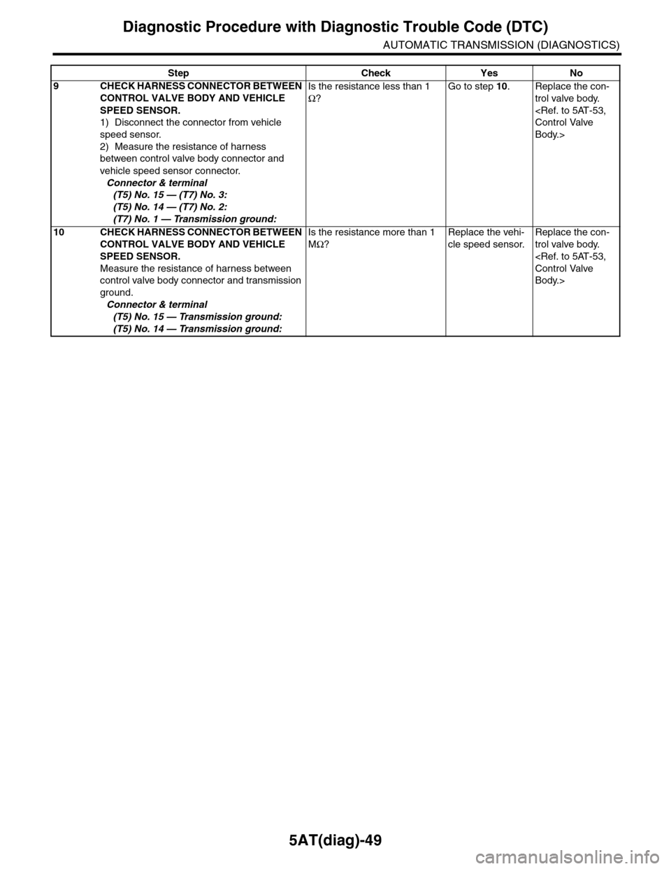
9CHECK HARNESS CONNECTOR BETWEEN
CONTROL VALVE BODY AND VEHICLE
SPEED SENSOR.
1) Disconnect the connector from vehicle
speed sensor.
2) Measure the resistance of harness
between control valve body connector and
vehicle speed sensor connector.
Connector & terminal
(T5) No. 15 — (T7) No. 3:
(T5) No. 14 — (T7) No. 2:
(T7) No. 1 — Transmission ground:
Is the resistance less than 1
Ω?
Go to step 10.Replace the con-
trol valve body.
Body.>
10 CHECK HARNESS CONNECTOR BETWEEN
CONTROL VALVE BODY AND VEHICLE
SPEED SENSOR.
Measure the resistance of harness between
control valve body connector and transmission
ground.
Connector & terminal
(T5) No. 15 — Transmission ground:
(T5) No. 14 — Transmission ground:
Is the resistance more than 1
MΩ?
Replace the vehi-
cle speed sensor.
Replace the con-
trol valve body.
Body.>
Step Check Yes No
Page 2168 of 2453
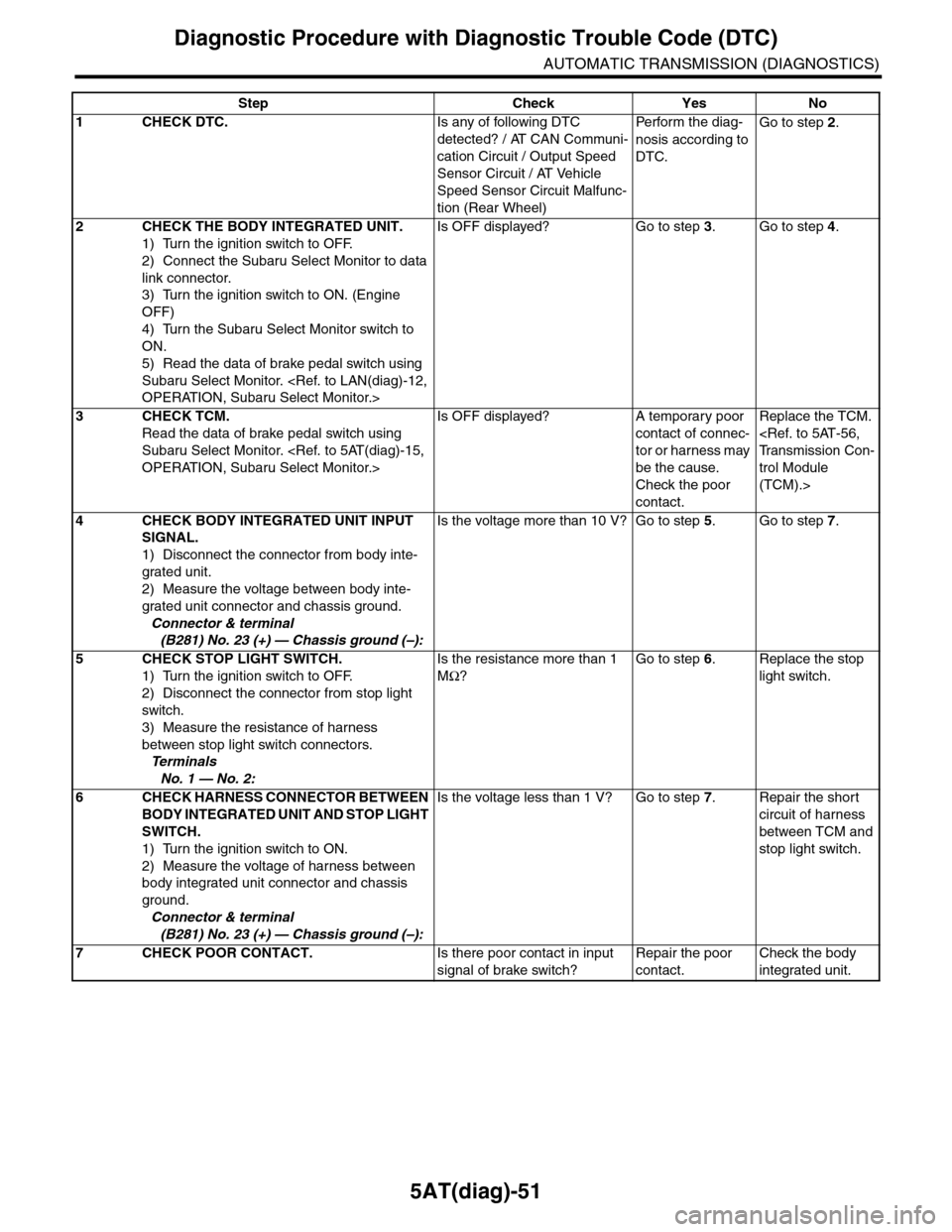
5AT(diag)-51
Diagnostic Procedure with Diagnostic Trouble Code (DTC)
AUTOMATIC TRANSMISSION (DIAGNOSTICS)
Step Check Yes No
1CHECK DTC.Is any of following DTC
detected? / AT CAN Communi-
cation Circuit / Output Speed
Sensor Circuit / AT Vehicle
Speed Sensor Circuit Malfunc-
tion (Rear Wheel)
Pe r for m t h e d ia g -
nosis according to
DTC.
Go to step 2.
2CHECK THE BODY INTEGRATED UNIT.
1) Turn the ignition switch to OFF.
2) Connect the Subaru Select Monitor to data
link connector.
3) Turn the ignition switch to ON. (Engine
OFF)
4) Turn the Subaru Select Monitor switch to
ON.
5) Read the data of brake pedal switch using
Subaru Select Monitor.
Is OFF displayed? Go to step 3.Go to step 4.
3CHECK TCM.
Read the data of brake pedal switch using
Subaru Select Monitor.
Is OFF displayed? A temporary poor
contact of connec-
tor or harness may
be the cause.
Check the poor
contact.
Replace the TCM.
trol Module
(TCM).>
4CHECK BODY INTEGRATED UNIT INPUT
SIGNAL.
1) Disconnect the connector from body inte-
grated unit.
2) Measure the voltage between body inte-
grated unit connector and chassis ground.
Connector & terminal
(B281) No. 23 (+) — Chassis ground (–):
Is the voltage more than 10 V? Go to step 5.Go to step 7.
5CHECK STOP LIGHT SWITCH.
1) Turn the ignition switch to OFF.
2) Disconnect the connector from stop light
switch.
3) Measure the resistance of harness
between stop light switch connectors.
Te r m i n a l s
No. 1 — No. 2:
Is the resistance more than 1
MΩ?
Go to step 6.Replace the stop
light switch.
6CHECK HARNESS CONNECTOR BETWEEN
BODY INTEGRATED UNIT AND STOP LIGHT
SWITCH.
1) Turn the ignition switch to ON.
2) Measure the voltage of harness between
body integrated unit connector and chassis
ground.
Connector & terminal
(B281) No. 23 (+) — Chassis ground (–):
Is the voltage less than 1 V? Go to step 7.Repair the short
circuit of harness
between TCM and
stop light switch.
7CHECK POOR CONTACT.Is there poor contact in input
signal of brake switch?
Repair the poor
contact.
Check the body
integrated unit.
Page 2169 of 2453
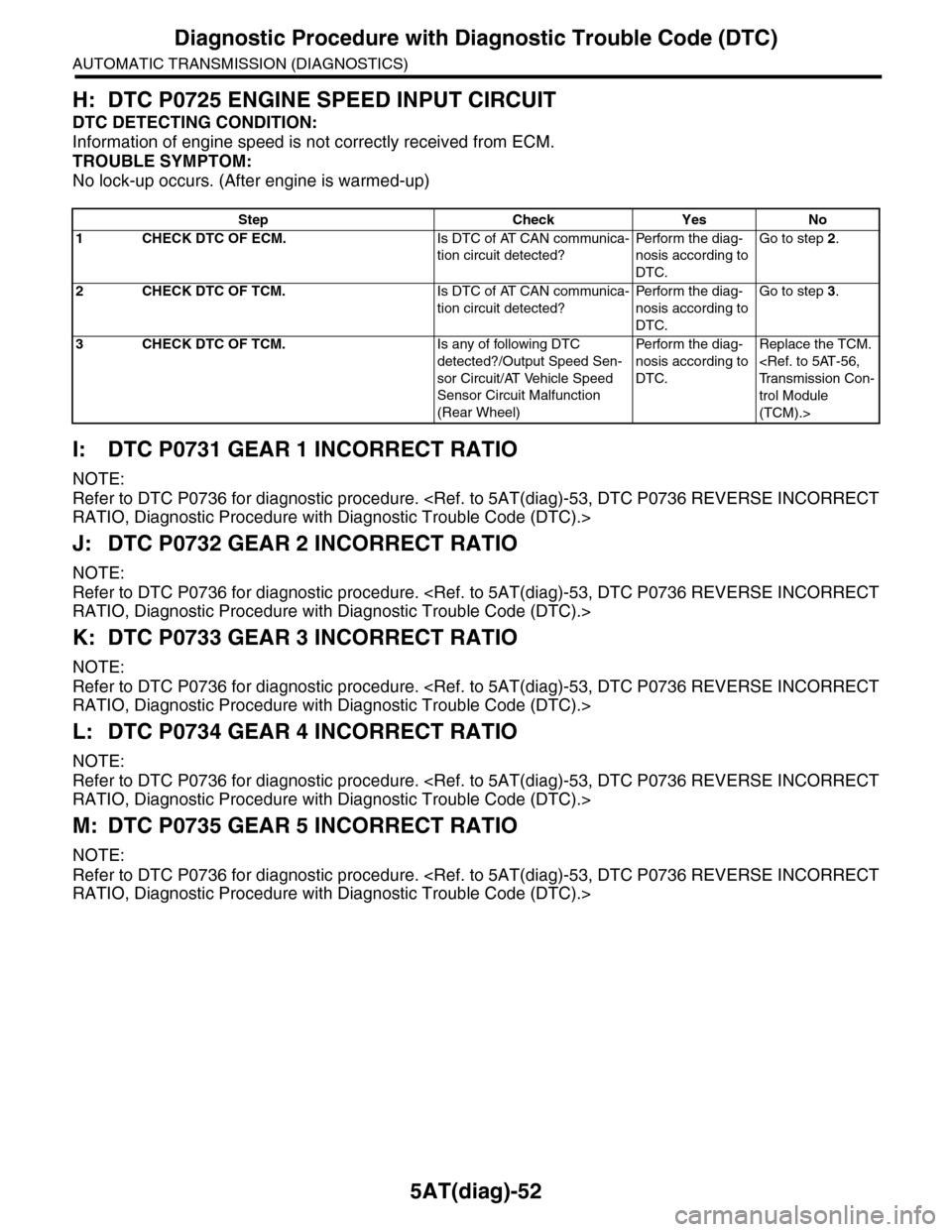
5AT(diag)-52
Diagnostic Procedure with Diagnostic Trouble Code (DTC)
AUTOMATIC TRANSMISSION (DIAGNOSTICS)
H: DTC P0725 ENGINE SPEED INPUT CIRCUIT
DTC DETECTING CONDITION:
Information of engine speed is not correctly received from ECM.
TROUBLE SYMPTOM:
No lock-up occurs. (After engine is warmed-up)
I: DTC P0731 GEAR 1 INCORRECT RATIO
NOTE:
Refer to DTC P0736 for diagnostic procedure.
J: DTC P0732 GEAR 2 INCORRECT RATIO
NOTE:
Refer to DTC P0736 for diagnostic procedure.
K: DTC P0733 GEAR 3 INCORRECT RATIO
NOTE:
Refer to DTC P0736 for diagnostic procedure.
L: DTC P0734 GEAR 4 INCORRECT RATIO
NOTE:
Refer to DTC P0736 for diagnostic procedure.
M: DTC P0735 GEAR 5 INCORRECT RATIO
NOTE:
Refer to DTC P0736 for diagnostic procedure.
Step Check Yes No
1CHECK DTC OF ECM.Is DTC of AT CAN communica-
tion circuit detected?
Pe r for m t h e d ia g -
nosis according to
DTC.
Go to step 2.
2CHECK DTC OF TCM.Is DTC of AT CAN communica-
tion circuit detected?
Pe r for m t h e d ia g -
nosis according to
DTC.
Go to step 3.
3CHECK DTC OF TCM.Is any of following DTC
detected?/Output Speed Sen-
sor Circuit/AT Vehicle Speed
Sensor Circuit Malfunction
(Rear Wheel)
Pe r for m t h e d ia g -
nosis according to
DTC.
Replace the TCM.
trol Module
(TCM).>
Page 2170 of 2453
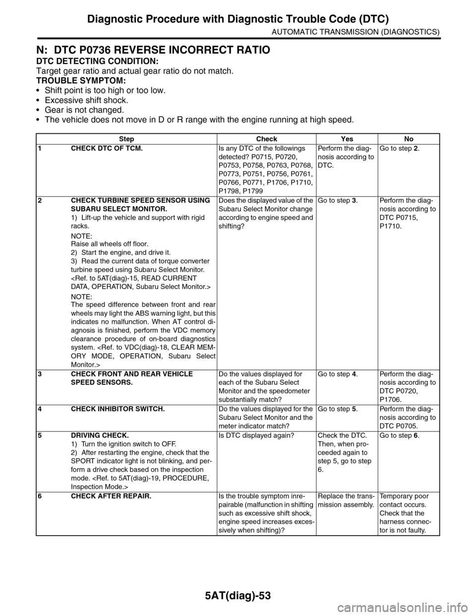
5AT(diag)-53
Diagnostic Procedure with Diagnostic Trouble Code (DTC)
AUTOMATIC TRANSMISSION (DIAGNOSTICS)
N: DTC P0736 REVERSE INCORRECT RATIO
DTC DETECTING CONDITION:
Target gear ratio and actual gear ratio do not match.
TROUBLE SYMPTOM:
•Shift point is too high or too low.
•Excessive shift shock.
•Gear is not changed.
•The vehicle does not move in D or R range with the engine running at high speed.
Step Check Yes No
1CHECK DTC OF TCM.Is any DTC of the followings
detected? P0715, P0720,
P0753, P0758, P0763, P0768,
P0773, P0751, P0756, P0761,
P0766, P0771, P1706, P1710,
P1798, P1799
Pe r for m t h e d ia g -
nosis according to
DTC.
Go to step 2.
2CHECK TURBINE SPEED SENSOR USING
SUBARU SELECT MONITOR.
1) Lift-up the vehicle and support with rigid
racks.
NOTE:Raise all wheels off floor.
2) Start the engine, and drive it.
3) Read the current data of torque converter
turbine speed using Subaru Select Monitor.
NOTE:The speed difference between front and rear
wheels may light the ABS warning light, but this
indicates no malfunction. When AT control di-
agnosis is finished, perform the VDC memory
clearance procedure of on-board diagnostics
system.
Monitor.>
Does the displayed value of the
Subaru Select Monitor change
according to engine speed and
shifting?
Go to step 3.Perform the diag-
nosis according to
DTC P0715,
P1710.
3CHECK FRONT AND REAR VEHICLE
SPEED SENSORS.
Do the values displayed for
each of the Subaru Select
Monitor and the speedometer
substantially match?
Go to step 4.Perform the diag-
nosis according to
DTC P0720,
P1706.
4CHECK INHIBITOR SWITCH.Do the values displayed for the
Subaru Select Monitor and the
meter indicator match?
Go to step 5.Perform the diag-
nosis according to
DTC P0705.
5DRIVING CHECK.
1) Turn the ignition switch to OFF.
2) After restarting the engine, check that the
SPORT indicator light is not blinking, and per-
form a drive check based on the inspection
mode.
Is DTC displayed again? Check the DTC.
Then, when pro-
ceeded again to
step 5, go to step
6.
Go to step 6.
6CHECK AFTER REPAIR.Is the trouble symptom inre-
pairable (malfunction in shifting
such as excessive shift shock,
engine speed increases exces-
sively when shifting)?
Replace the trans-
mission assembly.
Te m p o r a r y p o o r
contact occurs.
Check that the
harness connec-
tor is not faulty.
Page 2171 of 2453
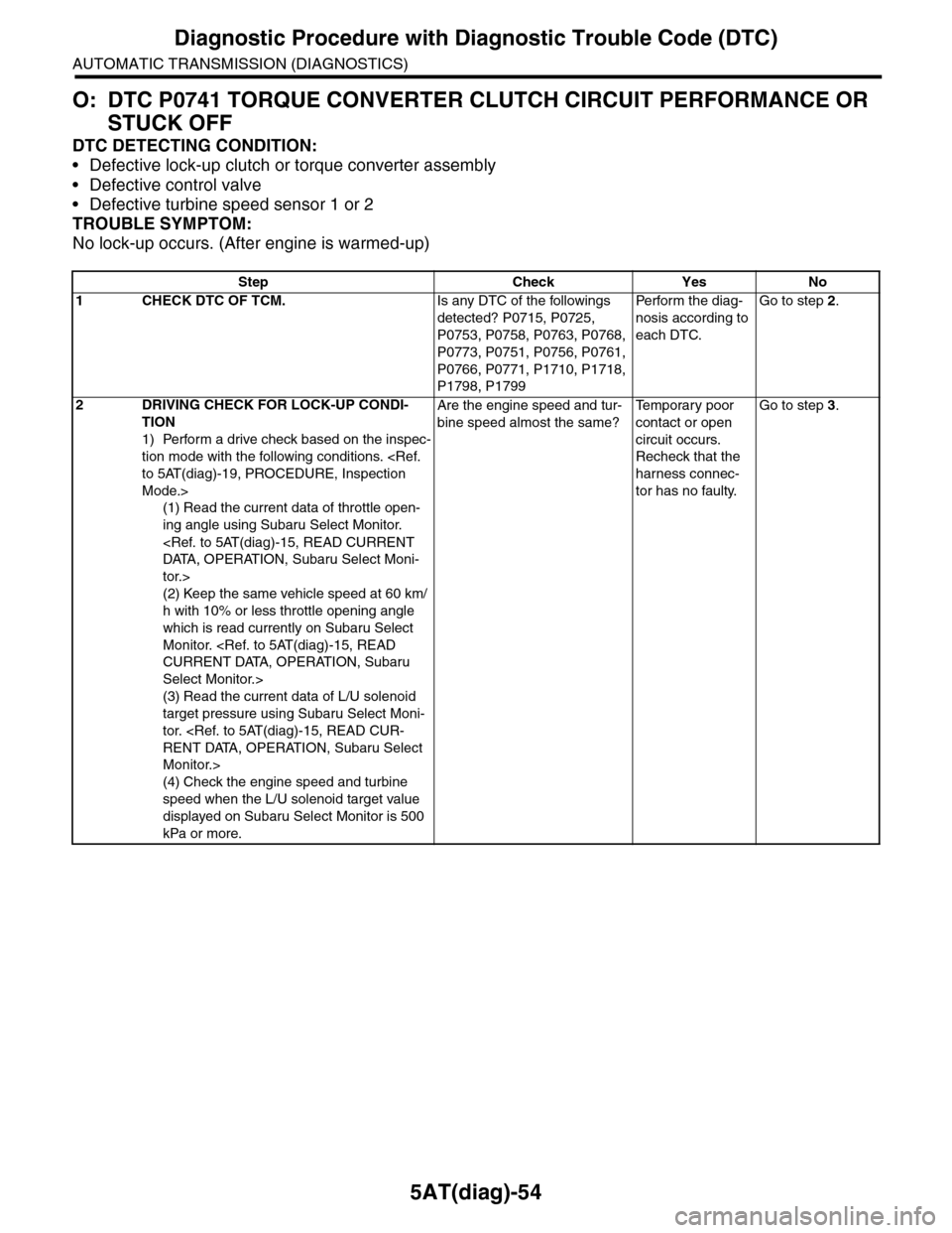
5AT(diag)-54
Diagnostic Procedure with Diagnostic Trouble Code (DTC)
AUTOMATIC TRANSMISSION (DIAGNOSTICS)
O: DTC P0741 TORQUE CONVERTER CLUTCH CIRCUIT PERFORMANCE OR
STUCK OFF
DTC DETECTING CONDITION:
•Defective lock-up clutch or torque converter assembly
•Defective control valve
•Defective turbine speed sensor 1 or 2
TROUBLE SYMPTOM:
No lock-up occurs. (After engine is warmed-up)
Step Check Yes No
1CHECK DTC OF TCM.Is any DTC of the followings
detected? P0715, P0725,
P0753, P0758, P0763, P0768,
P0773, P0751, P0756, P0761,
P0766, P0771, P1710, P1718,
P1798, P1799
Pe r for m t h e d ia g -
nosis according to
each DTC.
Go to step 2.
2DRIVING CHECK FOR LOCK-UP CONDI-
TION
1) Perform a drive check based on the inspec-
tion mode with the following conditions.
Mode.>
(1) Read the current data of throttle open-
ing angle using Subaru Select Monitor.
tor.>
(2) Keep the same vehicle speed at 60 km/
h with 10% or less throttle opening angle
which is read currently on Subaru Select
Monitor.
Select Monitor.>
(3) Read the current data of L/U solenoid
target pressure using Subaru Select Moni-
tor.
Monitor.>
(4) Check the engine speed and turbine
speed when the L/U solenoid target value
displayed on Subaru Select Monitor is 500
kPa or more.
Are the engine speed and tur-
bine speed almost the same?
Te m p o r a r y p o o r
contact or open
circuit occurs.
Recheck that the
harness connec-
tor has no faulty.
Go to step 3.
Page 2208 of 2453
5AT(diag)-91
Diagnostic Procedure with Diagnostic Trouble Code (DTC)
AUTOMATIC TRANSMISSION (DIAGNOSTICS)
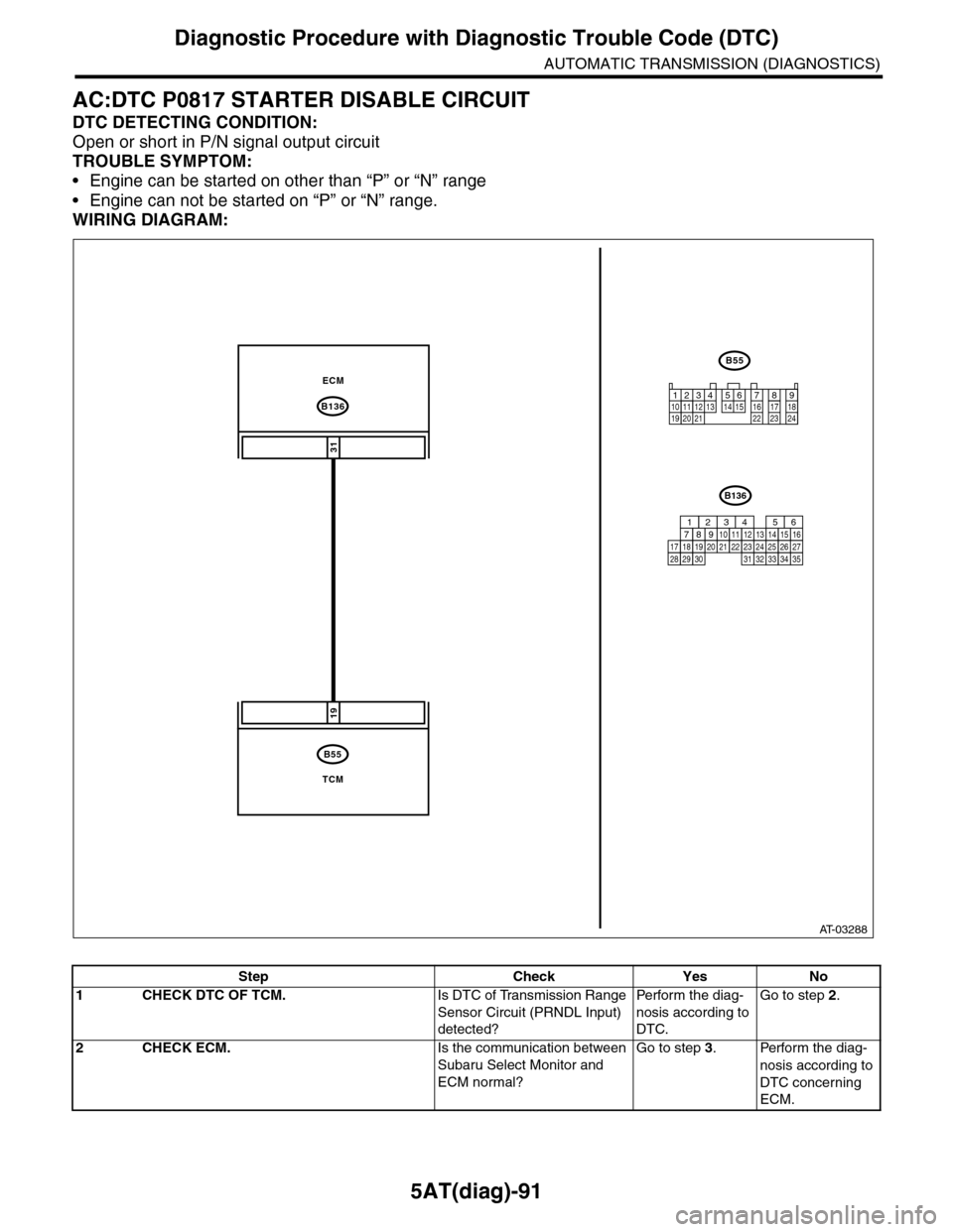
AC:DTC P0817 STARTER DISABLE CIRCUIT
DTC DETECTING CONDITION:
Open or short in P/N signal output circuit
TROUBLE SYMPTOM:
•Engine can be started on other than “P” or “N” range
•Engine can not be started on “P” or “N” range.
WIRING DIAGRAM:
AT-03288
B136
B55
31
19
ECM
TCM
B55
12341011 121920 21135614 1578916 17 1822 23 24
B136
16101112131415252430
9871718192028212223293231
123456
2726333435
Step Check Yes No
1CHECK DTC OF TCM.Is DTC of Transmission Range
Sensor Circuit (PRNDL Input)
detected?
Pe r for m t h e d ia g -
nosis according to
DTC.
Go to step 2.
2CHECK ECM.Is the communication between
Subaru Select Monitor and
ECM normal?
Go to step 3.Perform the diag-
nosis according to
DTC concerning
ECM.
Page 2213 of 2453
5AT(diag)-96
Diagnostic Procedure with Diagnostic Trouble Code (DTC)
AUTOMATIC TRANSMISSION (DIAGNOSTICS)
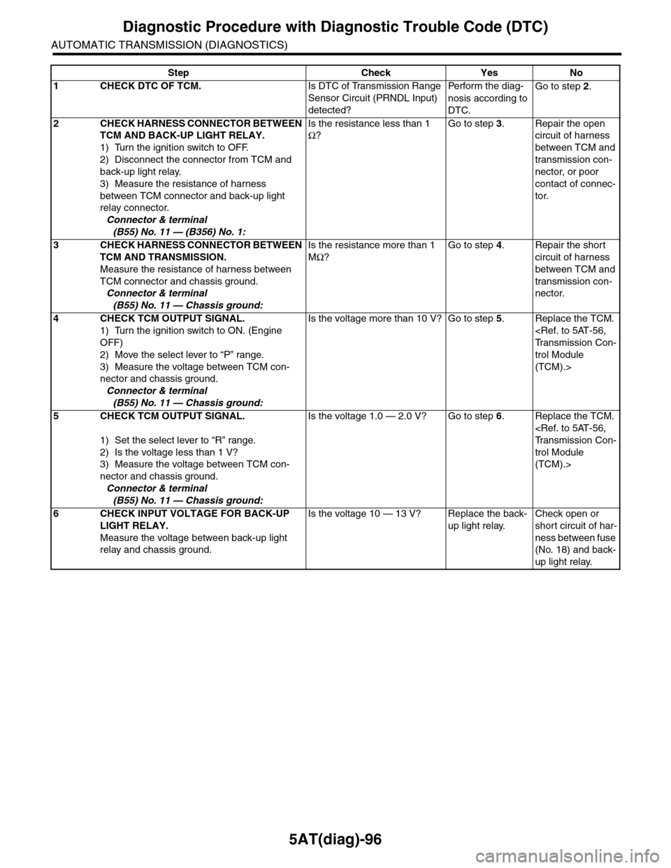
Step Check Yes No
1CHECK DTC OF TCM.Is DTC of Transmission Range
Sensor Circuit (PRNDL Input)
detected?
Pe r for m t h e d ia g -
nosis according to
DTC.
Go to step 2.
2CHECK HARNESS CONNECTOR BETWEEN
TCM AND BACK-UP LIGHT RELAY.
1) Turn the ignition switch to OFF.
2) Disconnect the connector from TCM and
back-up light relay.
3) Measure the resistance of harness
between TCM connector and back-up light
relay connector.
Connector & terminal
(B55) No. 11 — (B356) No. 1:
Is the resistance less than 1
Ω?
Go to step 3.Repair the open
circuit of harness
between TCM and
transmission con-
nector, or poor
contact of connec-
tor.
3CHECK HARNESS CONNECTOR BETWEEN
TCM AND TRANSMISSION.
Measure the resistance of harness between
TCM connector and chassis ground.
Connector & terminal
(B55) No. 11 — Chassis ground:
Is the resistance more than 1
MΩ?
Go to step 4.Repair the short
circuit of harness
between TCM and
transmission con-
nector.
4CHECK TCM OUTPUT SIGNAL.
1) Turn the ignition switch to ON. (Engine
OFF)
2) Move the select lever to “P” range.
3) Measure the voltage between TCM con-
nector and chassis ground.
Connector & terminal
(B55) No. 11 — Chassis ground:
Is the voltage more than 10 V? Go to step 5.Replace the TCM.
trol Module
(TCM).>
5CHECK TCM OUTPUT SIGNAL.
1) Set the select lever to “R” range.
2) Is the voltage less than 1 V?
3) Measure the voltage between TCM con-
nector and chassis ground.
Connector & terminal
(B55) No. 11 — Chassis ground:
Is the voltage 1.0 — 2.0 V? Go to step 6.Replace the TCM.
trol Module
(TCM).>
6CHECK INPUT VOLTAGE FOR BACK-UP
LIGHT RELAY.
Measure the voltage between back-up light
relay and chassis ground.
Is the voltage 10 — 13 V? Replace the back-
up light relay.
Check open or
short circuit of har-
ness between fuse
(No. 18) and back-
up light relay.