sensor SUBARU TRIBECA 2009 1.G Service Workshop Manual
[x] Cancel search | Manufacturer: SUBARU, Model Year: 2009, Model line: TRIBECA, Model: SUBARU TRIBECA 2009 1.GPages: 2453, PDF Size: 46.32 MB
Page 2123 of 2453
5AT(diag)-6
General Description
AUTOMATIC TRANSMISSION (DIAGNOSTICS)
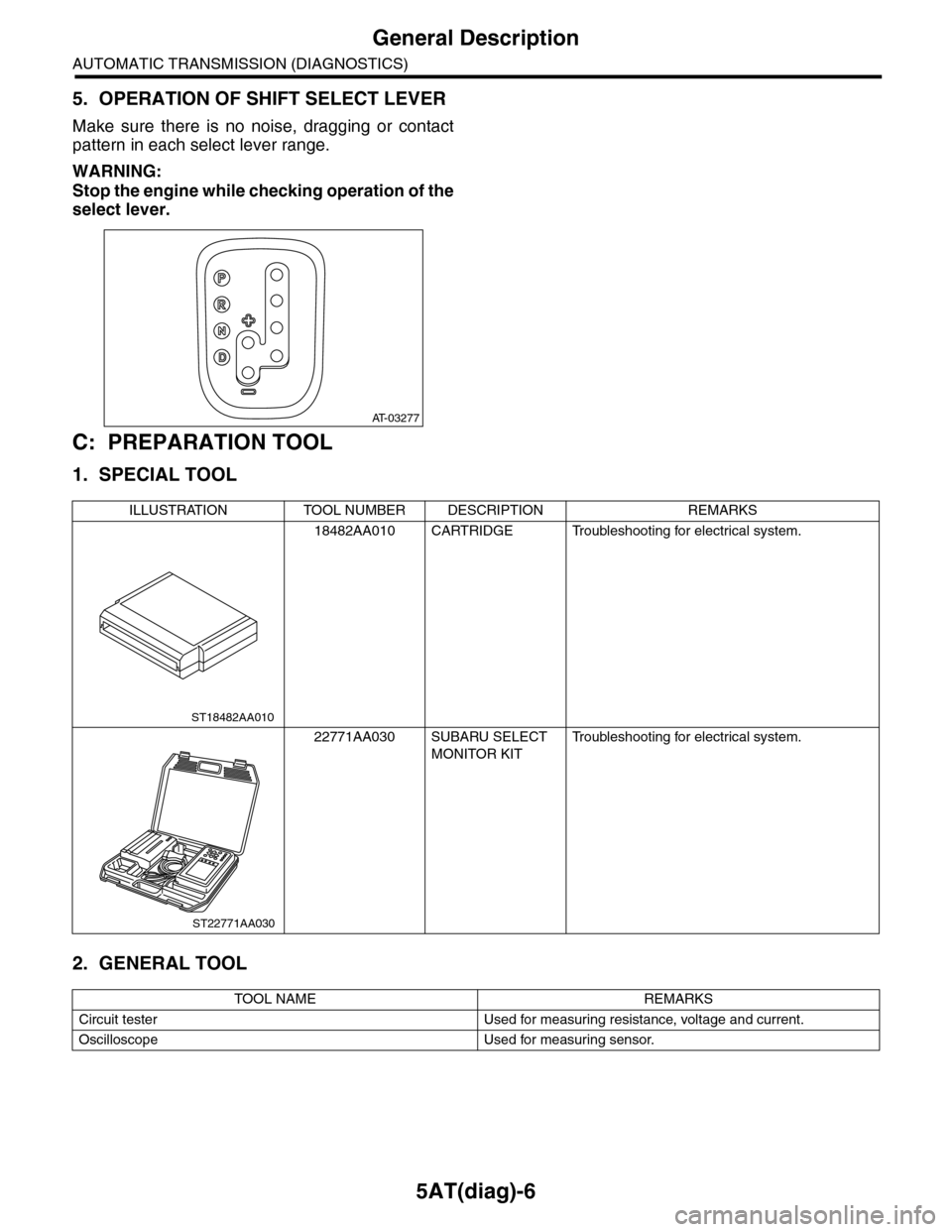
5. OPERATION OF SHIFT SELECT LEVER
Make sure there is no noise, dragging or contact
pattern in each select lever range.
WARNING:
Stop the engine while checking operation of the
select lever.
C: PREPARATION TOOL
1. SPECIAL TOOL
2. GENERAL TOOL
AT-03277
ILLUSTRATION TOOL NUMBER DESCRIPTION REMARKS
18482AA010 CARTRIDGE Troubleshooting for electrical system.
22771AA030 SUBARU SELECT
MONITOR KIT
Tr o u b l e s h o o t i n g f o r e l e c t r i c a l s y s t e m .
TOOL NAME REMARKS
Circuit tester Used for measuring resistance, voltage and current.
Oscilloscope Used for measuring sensor.
ST18482AA010
ST22771AA030
Page 2125 of 2453
5AT(diag)-8
Electrical Component Location
AUTOMATIC TRANSMISSION (DIAGNOSTICS)
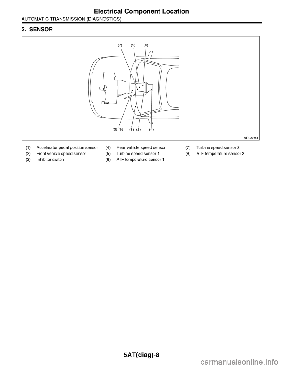
2. SENSOR
(1) Accelerator pedal position sensor (4) Rear vehicle speed sensor (7) Turbine speed sensor 2
(2) Front vehicle speed sensor (5) Turbine speed sensor 1 (8) ATF temperature sensor 2
(3) Inhibitor switch (6) ATF temperature sensor 1
AT-03280
(3) (6)
(5),(8) (2) (4)
(7)
(1)
Page 2129 of 2453
5AT(diag)-12
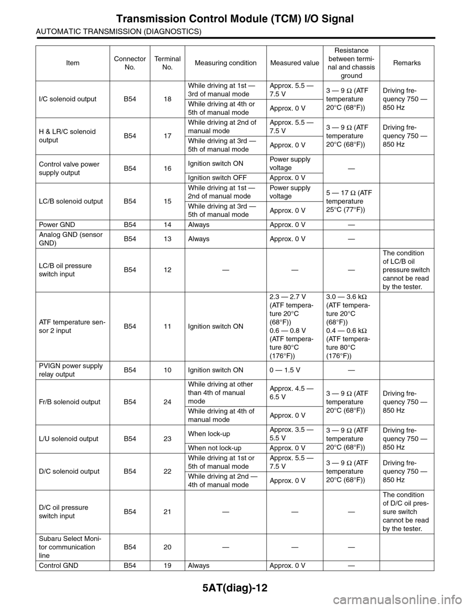
Transmission Control Module (TCM) I/O Signal
AUTOMATIC TRANSMISSION (DIAGNOSTICS)
I/C solenoid output B54 18
While driving at 1st —
3rd of manual mode
Approx. 5.5 —
7.5 V3 — 9 Ω (ATF
temperature
20°C (68°F))
Driving fre-
quency 750 —
850 HzWhile driving at 4th or
5th of manual modeApprox. 0 V
H & LR/C solenoid
outputB54 17
While driving at 2nd of
manual mode
Approx. 5.5 —
7.5 V3 — 9 Ω (ATF
temperature
20°C (68°F))
Driving fre-
quency 750 —
850 HzWhile driving at 3rd —
5th of manual modeApprox. 0 V
Control valve power
supply outputB54 16Ignition switch ONPow er s up p ly
voltage—
Ignition switch OFF Approx. 0 V
LC/B solenoid output B54 15
While driving at 1st —
2nd of manual mode
Pow er s up p ly
voltage5 — 17 Ω (ATF
temperature
25°C (77°F))
While driving at 3rd —
5th of manual modeApprox. 0 V
Pow er GN D B 5 4 1 4 A lways A pp r ox . 0 V —
Analog GND (sensor
GND)B54 13 Always Approx. 0 V —
LC/B oil pressure
switch inputB54 12 — — —
The condition
of LC/B oil
pressure switch
cannot be read
by the tester.
AT F t e m p e r a t u r e s e n -
sor 2 inputB54 11 Ignition switch ON
2.3 — 2.7 V
(ATF tempera-
ture 20°C
(68°F))
0.6 — 0.8 V
(ATF tempera-
ture 80°C
(176°F))
3.0 — 3.6 kΩ
(ATF tempera-
ture 20°C
(68°F))
0.4 — 0.6 kΩ
(ATF tempera-
ture 80°C
(176°F))
PVIGN power supply
relay outputB54 10 Ignition switch ON 0 — 1.5 V —
Fr / B so le n oi d o u tp u t B 5 4 2 4
While driving at other
than 4th of manual
mode
Approx. 4.5 —
6.5 V3 — 9 Ω (ATF
temperature
20°C (68°F))
Driving fre-
quency 750 —
850 HzWhile driving at 4th of
manual modeApprox. 0 V
L/U solenoid output B54 23When lock-upApprox. 3.5 —
5.5 V3 — 9 Ω (ATF
temperature
20°C (68°F))
Driving fre-
quency 750 —
850 HzWhen not lock-up Approx. 0 V
D/C solenoid output B54 22
While driving at 1st or
5th of manual mode
Approx. 5.5 —
7.5 V3 — 9 Ω (ATF
temperature
20°C (68°F))
Driving fre-
quency 750 —
850 HzWhile driving at 2nd —
4th of manual modeApprox. 0 V
D/C oil pressure
switch inputB54 21 — — —
The condition
of D/C oil pres-
sure switch
cannot be read
by the tester.
Subaru Select Moni-
tor communication
line
B54 20 — — —
Control GND B54 19 Always Approx. 0 V —
ItemConnector
No.
Te r m i n a l
No.Measuring condition Measured value
Resistance
between termi-
nal and chassis
ground
Remarks
Page 2130 of 2453
5AT(diag)-13
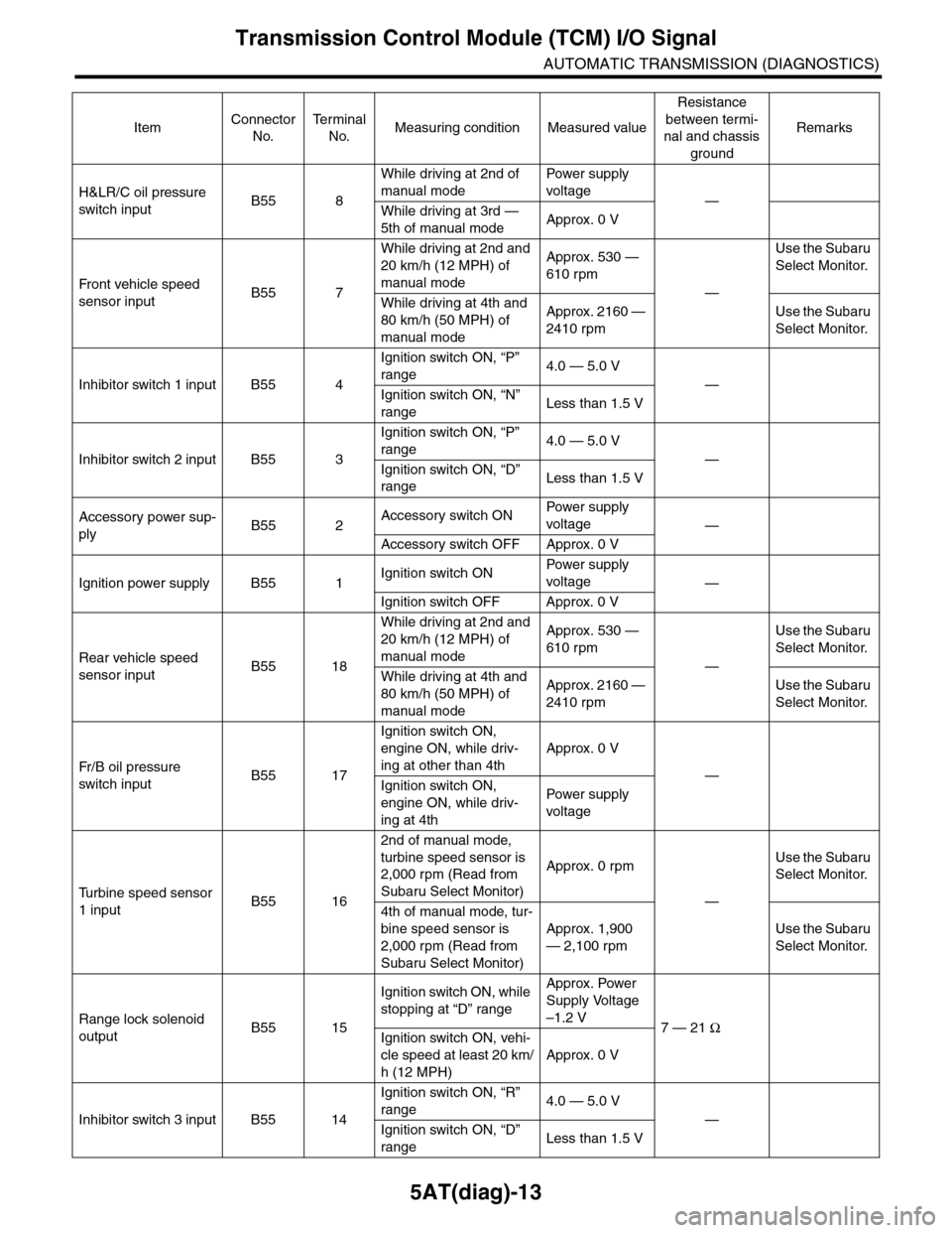
Transmission Control Module (TCM) I/O Signal
AUTOMATIC TRANSMISSION (DIAGNOSTICS)
H&LR/C oil pressure
switch inputB55 8
While driving at 2nd of
manual mode
Pow er s up p ly
voltage—
While driving at 3rd —
5th of manual modeApprox. 0 V
Fr o nt veh ic l e sp e ed
sensor inputB55 7
While driving at 2nd and
20 km/h (12 MPH) of
manual mode
Approx. 530 —
610 rpm
—
Use the Subaru
Select Monitor.
While driving at 4th and
80 km/h (50 MPH) of
manual mode
Approx. 2160 —
2410 rpm
Use the Subaru
Select Monitor.
Inhibitor switch 1 input B55 4
Ignition switch ON, “P”
range4.0 — 5.0 V
—
Ignition switch ON, “N”
rangeLess than 1.5 V
Inhibitor switch 2 input B55 3
Ignition switch ON, “P”
range4.0 — 5.0 V
—
Ignition switch ON, “D”
rangeLess than 1.5 V
Accessory power sup-
plyB55 2Accessory switch ONPow er s up p ly
voltage—
Accessory switch OFF Approx. 0 V
Ignition power supply B55 1Ignition switch ONPow er s up p ly
voltage—
Ignition switch OFF Approx. 0 V
Rear vehicle speed
sensor inputB55 18
While driving at 2nd and
20 km/h (12 MPH) of
manual mode
Approx. 530 —
610 rpm
—
Use the Subaru
Select Monitor.
While driving at 4th and
80 km/h (50 MPH) of
manual mode
Approx. 2160 —
2410 rpm
Use the Subaru
Select Monitor.
Fr / B oi l p r e ssu r e
switch inputB55 17
Ignition switch ON,
engine ON, while driv-
ing at other than 4th
Approx. 0 V
—
Ignition switch ON,
engine ON, while driv-
ing at 4th
Pow er s up p ly
voltage
Tu r b i n e s p e e d s e n s o r
1 inputB55 16
2nd of manual mode,
turbine speed sensor is
2,000 rpm (Read from
Subaru Select Monitor)
Approx. 0 rpm
—
Use the Subaru
Select Monitor.
4th of manual mode, tur-
bine speed sensor is
2,000 rpm (Read from
Subaru Select Monitor)
Approx. 1,900
— 2,100 rpm
Use the Subaru
Select Monitor.
Range lock solenoid
outputB55 15
Ignition switch ON, while
stopping at “D” range
Approx. Power
Supply Voltage
–1.2 V7 — 21 Ω
Ignition switch ON, vehi-
cle speed at least 20 km/
h (12 MPH)
Approx. 0 V
Inhibitor switch 3 input B55 14
Ignition switch ON, “R”
range4.0 — 5.0 V
—
Ignition switch ON, “D”
rangeLess than 1.5 V
ItemConnector
No.
Te r m i n a l
No.Measuring condition Measured value
Resistance
between termi-
nal and chassis
ground
Remarks
Page 2131 of 2453
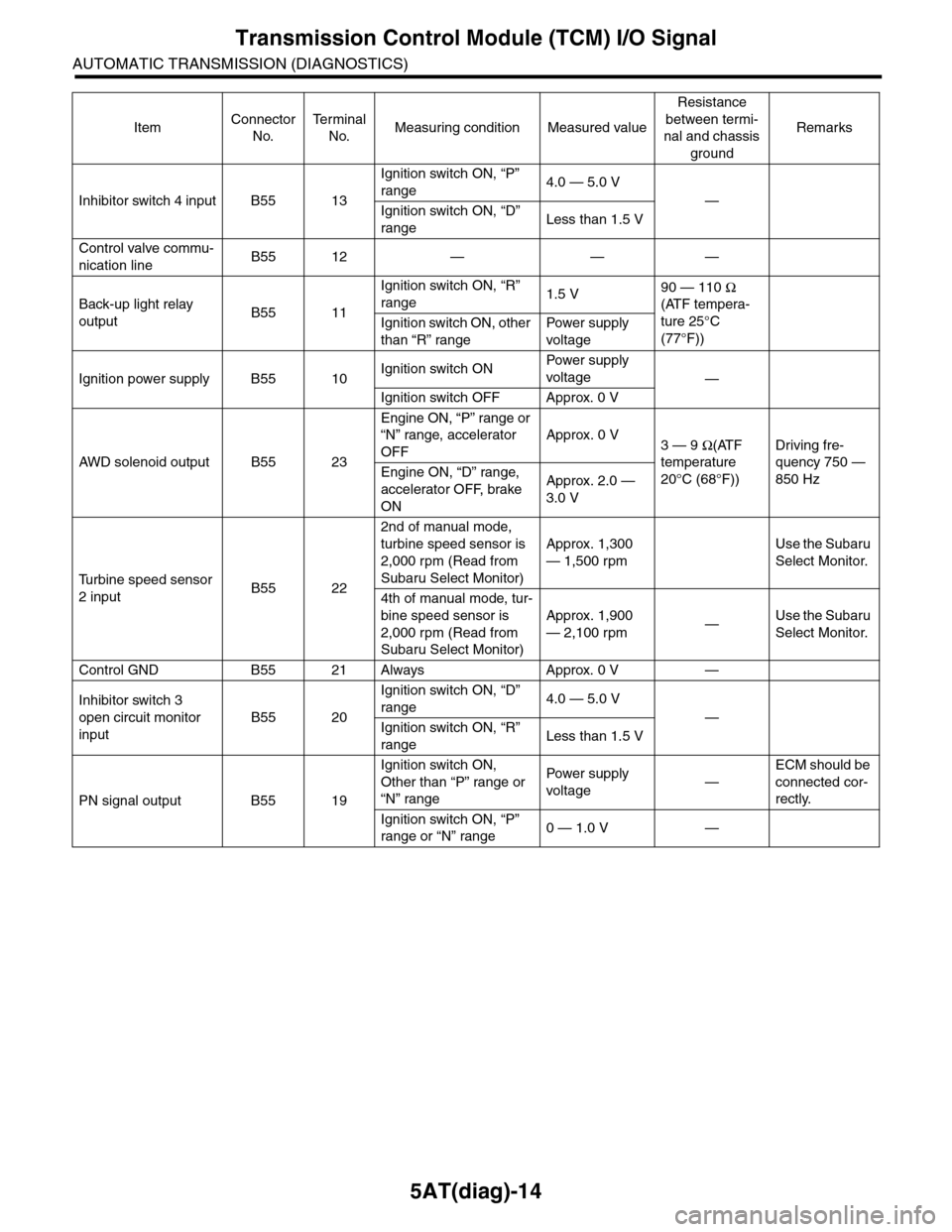
5AT(diag)-14
Transmission Control Module (TCM) I/O Signal
AUTOMATIC TRANSMISSION (DIAGNOSTICS)
Inhibitor switch 4 input B55 13
Ignition switch ON, “P”
range4.0 — 5.0 V
—
Ignition switch ON, “D”
rangeLess than 1.5 V
Control valve commu-
nication lineB55 12 — — —
Back-up light relay
outputB55 11
Ignition switch ON, “R”
range1.5 V90 — 110 Ω
(ATF tempera-
ture 25°C
(77°F))
Ignition switch ON, other
than “R” range
Pow er s up p ly
voltage
Ignition power supply B55 10Ignition switch ONPow er s up p ly
voltage—
Ignition switch OFF Approx. 0 V
AW D s o le n oi d o u tp u t B 5 5 2 3
Engine ON, “P” range or
“N” range, accelerator
OFF
Approx. 0 V3 — 9 Ω(ATF
temperature
20°C (68°F))
Driving fre-
quency 750 —
850 HzEngine ON, “D” range,
accelerator OFF, brake
ON
Approx. 2.0 —
3.0 V
Tu r b i n e s p e e d s e n s o r
2 inputB55 22
2nd of manual mode,
turbine speed sensor is
2,000 rpm (Read from
Subaru Select Monitor)
Approx. 1,300
— 1,500 rpm
Use the Subaru
Select Monitor.
4th of manual mode, tur-
bine speed sensor is
2,000 rpm (Read from
Subaru Select Monitor)
Approx. 1,900
— 2,100 rpm—Use the Subaru
Select Monitor.
Control GND B55 21 Always Approx. 0 V —
Inhibitor switch 3
open circuit monitor
input
B55 20
Ignition switch ON, “D”
range4.0 — 5.0 V
—
Ignition switch ON, “R”
rangeLess than 1.5 V
PN signal output B55 19
Ignition switch ON,
Other than “P” range or
“N” range
Pow er s up p ly
voltage—
ECM should be
connected cor-
rectly.
Ignition switch ON, “P”
range or “N” range0 — 1.0 V —
ItemConnector
No.
Te r m i n a l
No.Measuring condition Measured value
Resistance
between termi-
nal and chassis
ground
Remarks
Page 2133 of 2453
5AT(diag)-16
Subaru Select Monitor
AUTOMATIC TRANSMISSION (DIAGNOSTICS)
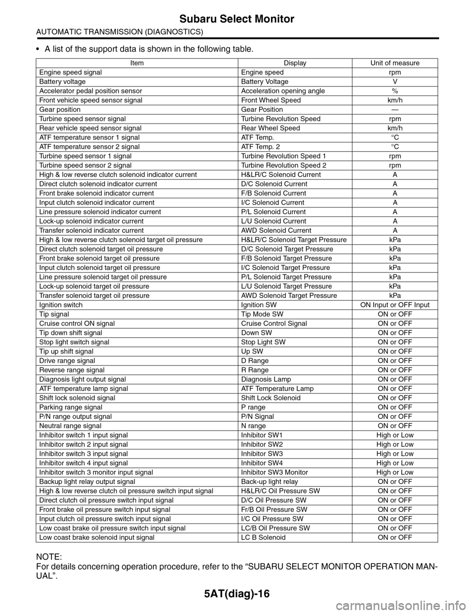
•A list of the support data is shown in the following table.
NOTE:
For details concerning operation procedure, refer to the “SUBARU SELECT MONITOR OPERATION MAN-
UAL”.
Item Display Unit of measure
Engine speed signal Engine speed rpm
Battery voltage Battery Voltage V
Accelerator pedal position sensor Acceleration opening angle %
Fr o nt veh ic l e sp e ed se n so r s ig n al Fr o n t W h ee l S p e ed km/ h
Gear position Gear Position —
Tu r b i n e s p e e d s e n s o r s i g n a l Tu r b i n e R e v o l u t i o n S p e e d r p m
Rear vehicle speed sensor signal Rear Wheel Speed km/h
ATF temperature sensor 1 signal ATF Temp. °C
ATF temperature sensor 2 signal ATF Temp. 2 °C
Tu r b i n e s p e e d s e n s o r 1 s i g n a l Tu r b i n e R e v o l u t i o n S p e e d 1 r p m
Tu r b i n e s p e e d s e n s o r 2 s i g n a l Tu r b i n e R e v o l u t i o n S p e e d 2 r p m
High & low reverse clutch solenoid indicator current H&LR/C Solenoid Current A
Direct clutch solenoid indicator current D/C Solenoid Current A
Fr o nt b rake so l en oi d in di c at o r c u rr e n t F / B S o l en o id Cur r e nt A
Input clutch solenoid indicator current I/C Solenoid Current A
Line pressure solenoid indicator current P/L Solenoid Current A
Lock-up solenoid indicator current L/U Solenoid Current A
Tr a n s f e r s o l e n o i d i n d i c a t o r c u r r e n t A W D S o l e n o i d C u r r e n t A
High & low reverse clutch solenoid target oil pressure H&LR/C Solenoid Target Pressure kPa
Direct clutch solenoid target oil pressure D/C Solenoid Target Pressure kPa
Fr o nt b rake so l en oi d ta r g et o il pr e ss ur e F / B S o l en o id Ta r g et P r es su r e kPa
Input clutch solenoid target oil pressure I/C Solenoid Target Pressure kPa
Line pressure solenoid target oil pressure P/L Solenoid Target Pressure kPa
Lock-up solenoid target oil pressure L/U Solenoid Target Pressure kPa
Tr a n s f e r s o l e n o i d t a r g e t o i l p r e s s u r e A W D S o l e n o i d Ta r g e t P r e s s u r e k P a
Ignition switch Ignition SW ON Input or OFF Input
Tip signal Tip Mode SW ON or OFF
Cruise control ON signal Cruise Control Signal ON or OFF
Tip down shift signal Down SW ON or OFF
Stop light switch signal Stop Light SW ON or OFF
Tip up shift signal Up SW ON or OFF
Drive range signal D Range ON or OFF
Reverse range signal R Range ON or OFF
Diagnosis light output signal Diagnosis Lamp ON or OFF
AT F t e m p e r a t u r e l a m p s i g n a l AT F Te m p e r a t u r e L a m p O N o r O F F
Shift lock solenoid signal Shift Lock Solenoid ON or OFF
Par king range signal P range ON or OFF
P/N range output signal P/N Signal ON or OFF
Neutral range signal N range ON or OFF
Inhibitor switch 1 input signal Inhibitor SW1 High or Low
Inhibitor switch 2 input signal Inhibitor SW2 High or Low
Inhibitor switch 3 input signal Inhibitor SW3 High or Low
Inhibitor switch 4 input signal Inhibitor SW4 High or Low
Inhibitor switch 3 monitor input signal Inhibitor SW3 Monitor High or Low
Backup light relay output signal Back-up light relay ON or OFF
High & low reverse clutch oil pressure switch input signal H&LR/C Oil Pressure SW ON or OFF
Direct clutch oil pressure switch input signal D/C Oil Pressure SW ON or OFF
Fr o nt b rake oi l pr e ss ur e swi tc h i n pu t si gn a l Fr / B Oi l P r e ss ur e S W ON or OF F
Input clutch oil pressure switch input signal I/C Oil Pressure SW ON or OFF
Low coast brake oil pressure switch input signal LC/B Oil Pressure SW ON or OFF
Low coast brake solenoid input signal LC B Solenoid ON or OFF
Page 2139 of 2453
5AT(diag)-22
SPORT Indicator Light Display
AUTOMATIC TRANSMISSION (DIAGNOSTICS)
11.SPORT Indicator Light Display
A: OPERATION
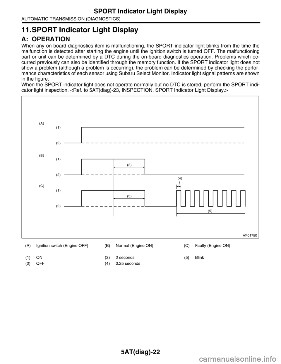
When any on-board diagnostics item is malfunctioning, the SPORT indicator light blinks from the time the
malfunction is detected after starting the engine until the ignition switch is turned OFF. The malfunctioning
part or unit can be determined by a DTC during the on-board diagnostics operation. Problems which oc-
curred previously can also be identified through the memory function. If the SPORT indicator light does not
show a problem (although a problem is occurring), the problem can be determined by checking the perfor-
mance characteristics of each sensor using Subaru Select Monitor. Indicator light signal patterns are shown
in the figure.
When the SPORT indicator light does not operate normally but no DTC is stored, perform the SPORT indi-
cator light inspection.
(A) Ignition switch (Engine OFF) (B) Normal (Engine ON) (C) Faulty (Engine ON)
(1) ON (3) 2 seconds (5) Blink
(2) OFF (4) 0.25 seconds
AT-01750
(4)
(3)
(1)
(2)
(1)
(2)
(1)
(2)
(3)
(5)
(A)
(B)
(C)
Page 2145 of 2453
5AT(diag)-28
List of Diagnostic Trouble Code (DTC)
AUTOMATIC TRANSMISSION (DIAGNOSTICS)
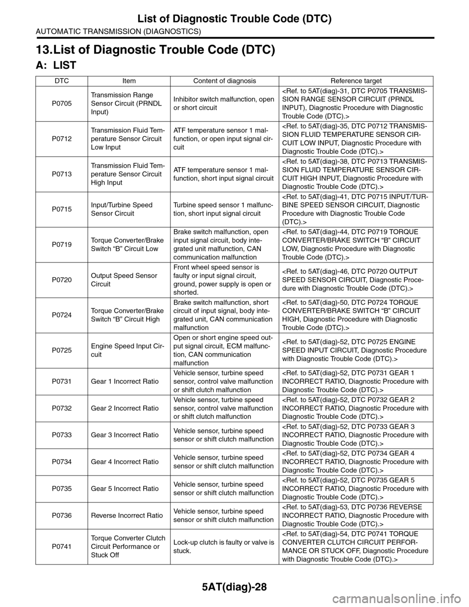
13.List of Diagnostic Trouble Code (DTC)
A: LIST
DTC Item Content of diagnosis Reference target
P0705
Tr a n s m i s s i o n R a n g e
Sensor Circuit (PRNDL
Input)
Inhibitor switch malfunction, open
or short circuit
INPUT), Diagnostic Procedure with Diagnostic
Tr o u b l e C o d e ( D T C ) . >
P0712
Tr a n s m i s s i o n F l u i d Te m -
perature Sensor Circuit
Low Input
AT F t e m p e r a t u r e s e n s o r 1 m a l -
function, or open input signal cir-
cuit
CUIT LOW INPUT, Diagnostic Procedure with
Diagnostic Trouble Code (DTC).>
P0713
Tr a n s m i s s i o n F l u i d Te m -
perature Sensor Circuit
High Input
AT F t e m p e r a t u r e s e n s o r 1 m a l -
function, short input signal circuit
CUIT HIGH INPUT, Diagnostic Procedure with
Diagnostic Trouble Code (DTC).>
P0715Input/Turbine Speed
Sensor Circuit
Tu r b i n e s p e e d s e n s o r 1 m a l f u n c -
tion, short input signal circuit
Procedure with Diagnostic Trouble Code
(DTC).>
P0719To r q u e C o n v e r t e r / B r a k e
Switch “B” Circuit Low
Brake switch malfunction, open
input signal circuit, body inte-
grated unit malfunction, CAN
communication malfunction
LOW, Diagnostic Procedure with Diagnostic
Tr o u b l e C o d e ( D T C ) . >
P0720Output Speed Sensor
Circuit
Front wheel speed sensor is
faulty or input signal circuit,
ground, power supply is open or
shorted.
dure with Diagnostic Trouble Code (DTC).>
P0724To r q u e C o n v e r t e r / B r a k e
Switch “B” Circuit High
Brake switch malfunction, short
circuit of input signal, body inte-
grated unit, CAN communication
malfunction
HIGH, Diagnostic Procedure with Diagnostic
Tr o u b l e C o d e ( D T C ) . >
P0725Engine Speed Input Cir-
cuit
Open or short engine speed out-
put signal circuit, ECM malfunc-
tion, CAN communication
malfunction
with Diagnostic Trouble Code (DTC).>
P0731 Gear 1 Incorrect Ratio
Ve h i c l e s e n s o r, t u r b i n e s p e e d
sensor, control valve malfunction
or shift clutch malfunction
Diagnostic Trouble Code (DTC).>
P0732 Gear 2 Incorrect Ratio
Ve h i c l e s e n s o r, t u r b i n e s p e e d
sensor, control valve malfunction
or shift clutch malfunction
Diagnostic Trouble Code (DTC).>
P0733 Gear 3 Incorrect RatioVe h i c l e s e n s o r, t u r b i n e s p e e d
sensor or shift clutch malfunction
Diagnostic Trouble Code (DTC).>
P0734 Gear 4 Incorrect RatioVe h i c l e s e n s o r, t u r b i n e s p e e d
sensor or shift clutch malfunction
Diagnostic Trouble Code (DTC).>
P0735 Gear 5 Incorrect RatioVe h i c l e s e n s o r, t u r b i n e s p e e d
sensor or shift clutch malfunction
Diagnostic Trouble Code (DTC).>
P0736 Reverse Incorrect RatioVe h i c l e s e n s o r, t u r b i n e s p e e d
sensor or shift clutch malfunction
Diagnostic Trouble Code (DTC).>
P0741
To r q u e C o n v e r t e r C l u t c h
Circuit Performance or
Stuck Off
Lock-up clutch is faulty or valve is
stuck.
MANCE OR STUCK OFF, Diagnostic Procedure
with Diagnostic Trouble Code (DTC).>
Page 2147 of 2453
5AT(diag)-30
List of Diagnostic Trouble Code (DTC)
AUTOMATIC TRANSMISSION (DIAGNOSTICS)
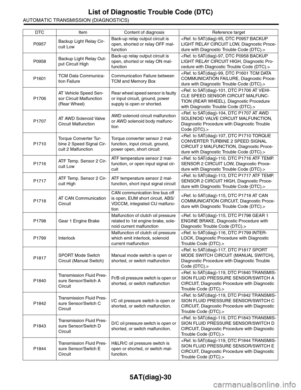
P0957Backup Light Relay Cir-
cuit Low
Back-up relay output circuit is
open, shorted or relay OFF mal-
function
dure with Diagnostic Trouble Code (DTC).>
P0958Backup Light Relay Out-
put Circuit High
Back-up relay output circuit is
open, shorted or relay ON mal-
function
cedure with Diagnostic Trouble Code (DTC).>
P1601TCM Data Communica-
tion Failure
Communication Failure between
TCM and Memory Box
dure with Diagnostic Trouble Code (DTC).>
P1706
AT Ve h i c l e S p e e d S e n -
sor Circuit Malfunction
(Rear Wheel)
Rear wheel speed sensor is faulty
or input circuit, ground, power
supply is open or shorted.
TION (REAR WHEEL), Diagnostic Procedure
with Diagnostic Trouble Code (DTC).>
P1707AT A W D S o l e n o i d V a l v e
Circuit Malfunction
AWD solenoid circuit malfunction
or AWD solenoid body malfunc-
tion
Diagnostic Procedure with Diagnostic Trouble
Code (DTC).>
P1710
To r q u e C o n v e r t e r Tu r -
bine 2 Speed Signal Cir-
cuit 2 Malfunction
To r q u e c o n v e r t e r s e n s o r 2 m a l -
function, input circuit, ground,
power open, short circuit
CIRCUIT 2 MALFUNCTION, Diagnostic Proce-
dure with Diagnostic Trouble Code (DTC).>
P1716AT F Te m p . S e n s o r 2 C i r -
cuit Low
AT F t e m p e r a t u r e s e n s o r 2 m a l -
function, or open input signal cir-
cuit
dure with Diagnostic Trouble Code (DTC).>
P1717AT F Te m p . S e n s o r 2 C i r -
cuit High
AT F t e m p e r a t u r e s e n s o r 2 m a l -
function, short input signal circuit
dure with Diagnostic Trouble Code (DTC).>
P1718AT C A N C o m m u n i c a t i o n
Circuit
CAN communication line bus off
is open, EUM short circuit, ABS/
VDCCM, integrated CU malfunc-
tion
dure with Diagnostic Trouble Code (DTC).>
P1798 Gear 1 Engine Brake
Malfunction of clutch oil pressure
related to 1st engine brake, sole-
noid current malfunction
Diagnostic Trouble Code (DTC).>
P1799 Interlock
Malfunction of clutch oil pressure
which emit interlock, solenoid
current malfunction
Tr o u b l e C o d e ( D T C ) . >
P1817SPORT Mode Switch
Circuit (Manual Switch)
Manual mode switch is open or
shorted, or switch malfunction
Diagnostic Procedure with Diagnostic Trouble
Code (DTC).>
P1840
Tr a n s m i s s i o n F l u i d P r e s -
sure Sensor/Switch A
Circuit
Fr/B oil pressure switch is open or
shorted, or switch malfunction
CIRCUIT, Diagnostic Procedure with Diagnostic
Tr o u b l e C o d e ( D T C ) . >
P1842
Tr a n s m i s s i o n F l u i d P r e s -
sure Sensor/Switch C
Circuit
I/C oil pressure switch is open or
shorted, or switch malfunction.
CIRCUIT, Diagnostic Procedure with Diagnostic
Tr o u b l e C o d e ( D T C ) . >
P1843
Tr a n s m i s s i o n F l u i d P r e s -
sure Sensor/Switch D
Circuit
D/C oil pressure switch is open or
shorted, or switch malfunction.
CIRCUIT, Diagnostic Procedure with Diagnostic
Tr o u b l e C o d e ( D T C ) . >
P1844
Tr a n s m i s s i o n F l u i d P r e s -
sure Sensor/Switch E
Circuit
H&LR/C oil pressure switch is
open or shorted, or switch mal-
function.
CIRCUIT, Diagnostic Procedure with Diagnostic
Tr o u b l e C o d e ( D T C ) . >
DTC Item Content of diagnosis Reference target
Page 2148 of 2453
5AT(diag)-31
Diagnostic Procedure with Diagnostic Trouble Code (DTC)
AUTOMATIC TRANSMISSION (DIAGNOSTICS)
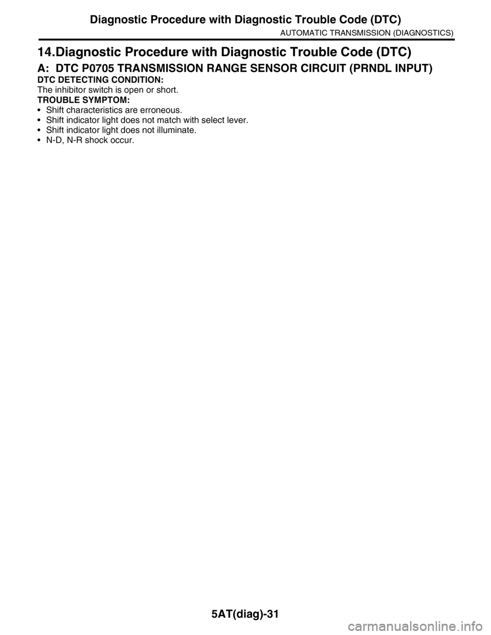
14.Diagnostic Procedure with Diagnostic Trouble Code (DTC)
A: DTC P0705 TRANSMISSION RANGE SENSOR CIRCUIT (PRNDL INPUT)
DTC DETECTING CONDITION:
The inhibitor switch is open or short.
TROUBLE SYMPTOM:
•Shift characteristics are erroneous.
•Shift indicator light does not match with select lever.
•Shift indicator light does not illuminate.
•N-D, N-R shock occur.