SUBARU TRIBECA 2009 1.G Service Workshop Manual
Manufacturer: SUBARU, Model Year: 2009, Model line: TRIBECA, Model: SUBARU TRIBECA 2009 1.GPages: 2453, PDF Size: 46.32 MB
Page 711 of 2453
WW-16
Front Wiper Motor and Link
WIPER AND WASHER SYSTEMS
8. Front Wiper Motor and Link
A: REMOVAL
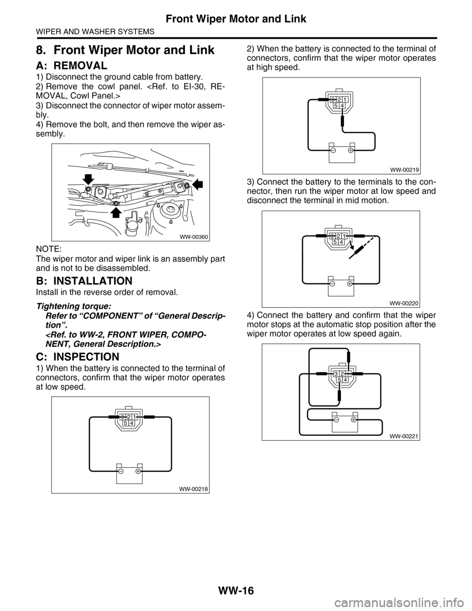
1) Disconnect the ground cable from battery.
2) Remove the cowl panel.
3) Disconnect the connector of wiper motor assem-
bly.
4) Remove the bolt, and then remove the wiper as-
sembly.
NOTE:
The wiper motor and wiper link is an assembly part
and is not to be disassembled.
B: INSTALLATION
Install in the reverse order of removal.
Tightening torque:
Refer to “COMPONENT” of “General Descrip-
tion”.
C: INSPECTION
1) When the battery is connected to the terminal of
connectors, confirm that the wiper motor operates
at low speed.
2) When the battery is connected to the terminal of
connectors, confirm that the wiper motor operates
at high speed.
3) Connect the battery to the terminals to the con-
nector, then run the wiper motor at low speed and
disconnect the terminal in mid motion.
4) Connect the battery and confirm that the wiper
motor stops at the automatic stop position after the
wiper motor operates at low speed again.
WW-00360
WW-00218
32541
32541
WW-00219
WW-00220
32541
WW-00221
32541
Page 712 of 2453
WW-17
Front Washer Nozzle
WIPER AND WASHER SYSTEMS
9. Front Washer Nozzle
A: REMOVAL
1) Remove the front hood insulator.
Front Hood.>
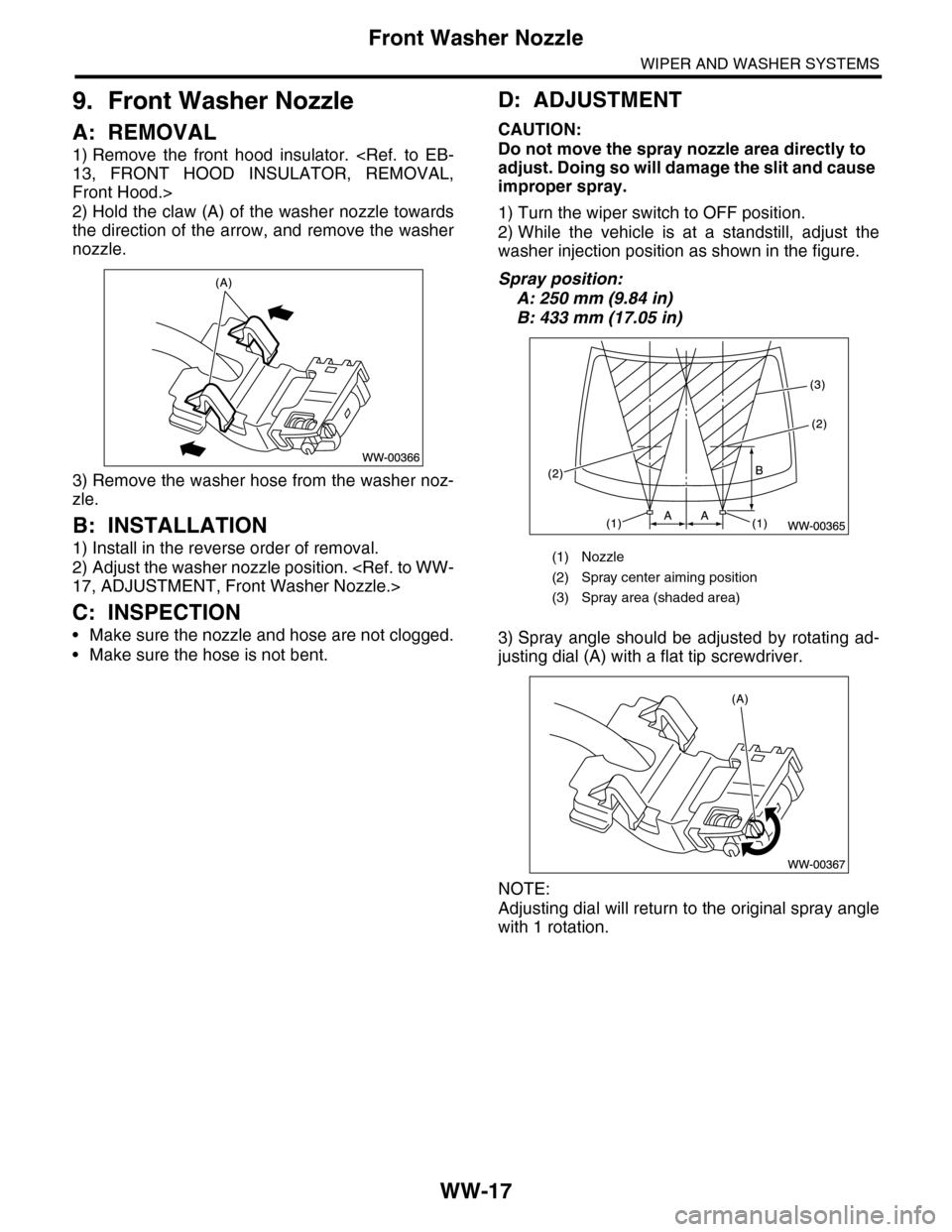
2) Hold the claw (A) of the washer nozzle towards
the direction of the arrow, and remove the washer
nozzle.
3) Remove the washer hose from the washer noz-
zle.
B: INSTALLATION
1) Install in the reverse order of removal.
2) Adjust the washer nozzle position.
C: INSPECTION
•Make sure the nozzle and hose are not clogged.
•Make sure the hose is not bent.
D: ADJUSTMENT
CAUTION:
Do not move the spray nozzle area directly to
adjust. Doing so will damage the slit and cause
improper spray.
1) Turn the wiper switch to OFF position.
2) While the vehicle is at a standstill, adjust the
washer injection position as shown in the figure.
Spray position:
A: 250 mm (9.84 in)
B: 433 mm (17.05 in)
3) Spray angle should be adjusted by rotating ad-
justing dial (A) with a flat tip screwdriver.
NOTE:
Adjusting dial will return to the original spray angle
with 1 rotation.
(1) Nozzle
(2) Spray center aiming position
(3) Spray area (shaded area)
Page 713 of 2453
WW-18
Rear Wiper Arm
WIPER AND WASHER SYSTEMS
10.Rear Wiper Arm
A: REMOVAL
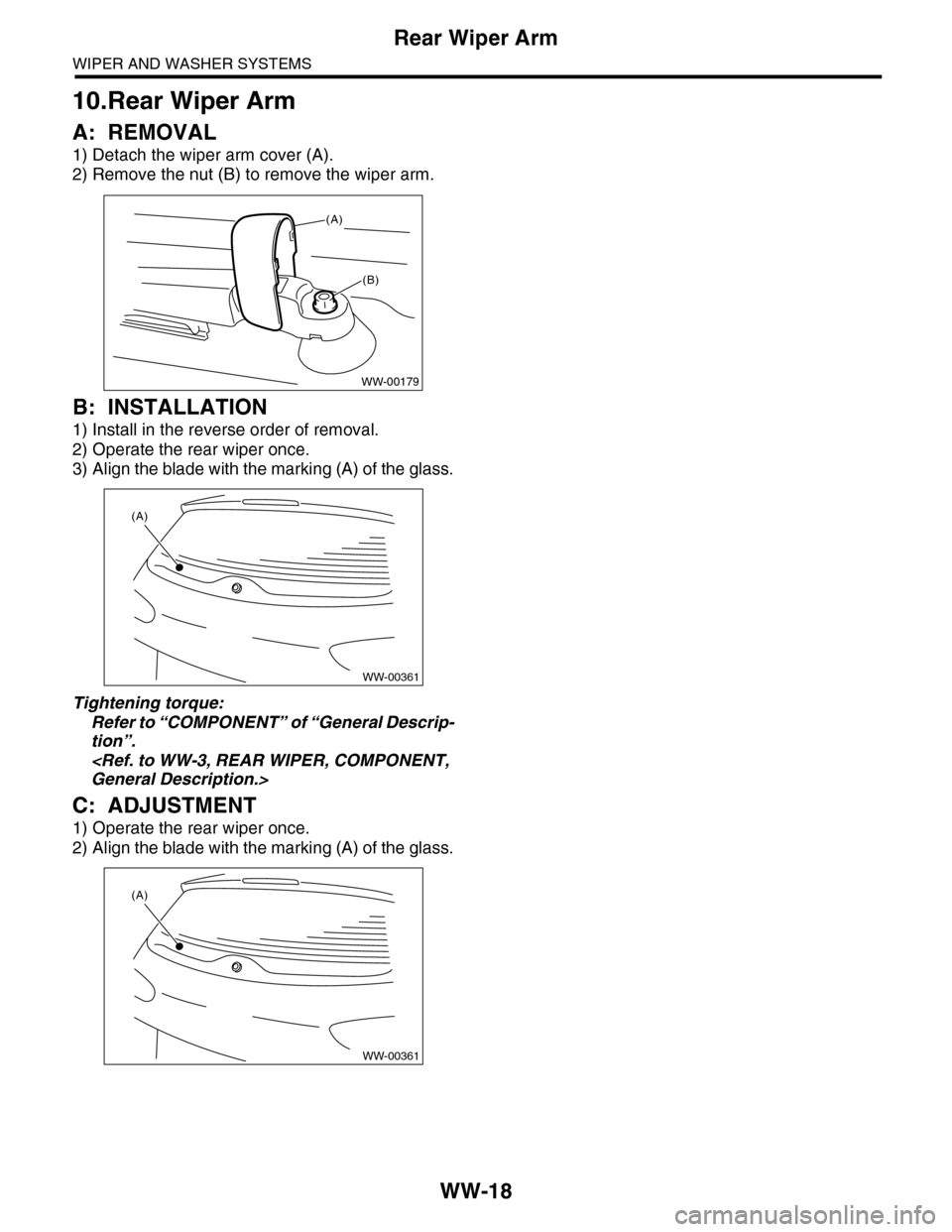
1) Detach the wiper arm cover (A).
2) Remove the nut (B) to remove the wiper arm.
B: INSTALLATION
1) Install in the reverse order of removal.
2) Operate the rear wiper once.
3) Align the blade with the marking (A) of the glass.
Tightening torque:
Refer to “COMPONENT” of “General Descrip-
tion”.
C: ADJUSTMENT
1) Operate the rear wiper once.
2) Align the blade with the marking (A) of the glass.
WW-00179
(A)
(B)
WW-00361
(A)
WW-00361
(A)
Page 714 of 2453
WW-19
Rear Wiper Motor
WIPER AND WASHER SYSTEMS
11.Rear Wiper Motor
A: REMOVAL
1) Disconnect the ground cable from battery.
2) Remove the rear wiper arm.
3) Remove the rear gate lower trim.
4) Disconnect the harness connector of wiper mo-
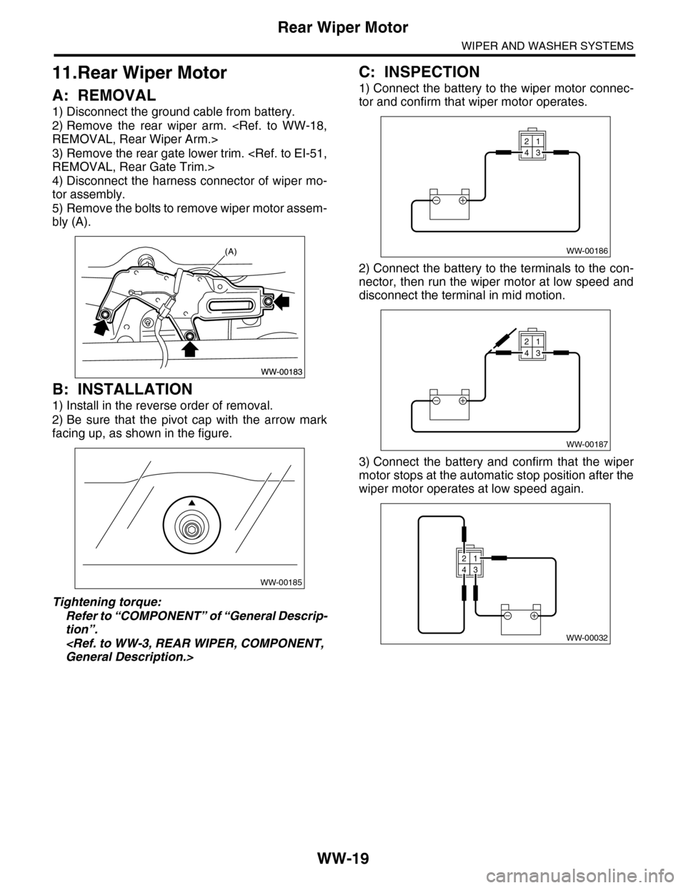
tor assembly.
5) Remove the bolts to remove wiper motor assem-
bly (A).
B: INSTALLATION
1) Install in the reverse order of removal.
2) Be sure that the pivot cap with the arrow mark
facing up, as shown in the figure.
Tightening torque:
Refer to “COMPONENT” of “General Descrip-
tion”.
C: INSPECTION
1) Connect the battery to the wiper motor connec-
tor and confirm that wiper motor operates.
2) Connect the battery to the terminals to the con-
nector, then run the wiper motor at low speed and
disconnect the terminal in mid motion.
3) Connect the battery and confirm that the wiper
motor stops at the automatic stop position after the
wiper motor operates at low speed again.
WW-00185
WW-00186
21
43
WW-00187
21
43
WW-00032
21
43
Page 715 of 2453
WW-20
Rear Washer
WIPER AND WASHER SYSTEMS
12.Rear Washer
A: REMOVAL
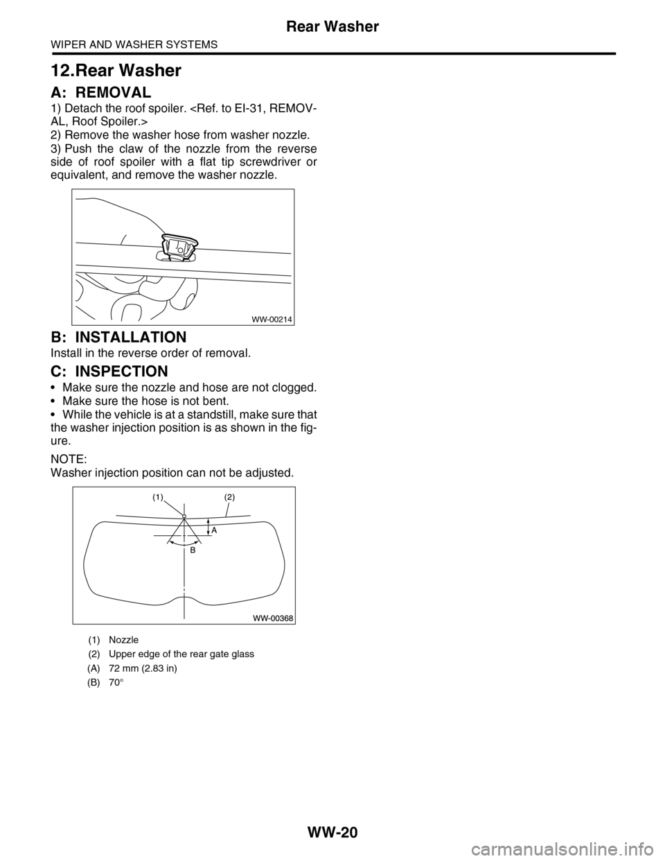
1) Detach the roof spoiler.
2) Remove the washer hose from washer nozzle.
3) Push the claw of the nozzle from the reverse
side of roof spoiler with a flat tip screwdriver or
equivalent, and remove the washer nozzle.
B: INSTALLATION
Install in the reverse order of removal.
C: INSPECTION
•Make sure the nozzle and hose are not clogged.
•Make sure the hose is not bent.
•While the vehicle is at a standstill, make sure that
the washer injection position is as shown in the fig-
ure.
NOTE:
Washer injection position can not be adjusted.
(1) Nozzle
(2) Upper edge of the rear gate glass
(A) 72 mm (2.83 in)
(B) 70°
WW-00214
Page 716 of 2453
BR-2
General Description
BRAKE
1. General Description
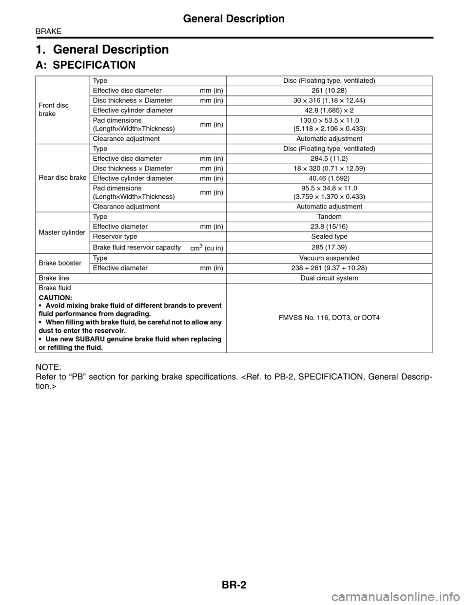
A: SPECIFICATION
NOTE:
Refer to “PB” section for parking brake specifications.
Fr o nt d is c
brake
Ty p e D i s c ( F l o a t i n g t y p e , v e n t i l a t e d )
Effective disc diameter mm (in) 261 (10.28)
Disc thickness × Diameter mm (in) 30 × 316 (1.18 × 12.44)
Effective cylinder diameter 42.8 (1.685) × 2
Pad dimensions
(Length×Width×Thickness)mm (in)130.0 × 53.5 × 11.0
(5.118 × 2.106 × 0.433)
Clearance adjustment Automatic adjustment
Rear disc brake
Ty p e D i s c ( F l o a t i n g t y p e , v e n t i l a t e d )
Effective disc diameter mm (in) 284.5 (11.2)
Disc thickness × Diameter mm (in) 18 × 320 (0.71 × 12.59)
Effective cylinder diameter mm (in) 40.46 (1.592)
Pad dimensions
(Length×Width×Thickness)mm (in)95.5 × 34.8 × 11.0
(3.759 × 1.370 × 0.433)
Clearance adjustment Automatic adjustment
Master cylinder
Ty p e Ta n d e m
Effective diameter mm (in) 23.8 (15/16)
Reservoir type Sealed type
Brake fluid reservoir capacitycm3 (cu in)285 (17.39)
Brake boosterTy p e V a c u u m s u s p e n d e d
Effective diameter mm (in) 238 + 261 (9.37 + 10.28)
Brake lineDual circuit system
Brake fluid
CAUTION:
•Avoid mixing brake fluid of different brands to prevent
fluid performance from degrading.
•When filling with brake fluid, be careful not to allow any
dust to enter the reservoir.
•Use new SUBARU genuine brake fluid when replacing
or refilling the fluid.
FMVSS No. 116, DOT3, or DOT4
Page 717 of 2453
BR-3
General Description
BRAKE
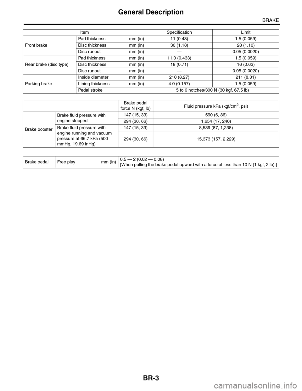
Item Specification Limit
Fr o nt b rake
Pad thickness mm (in) 11 (0.43) 1.5 (0.059)
Disc thickness mm (in) 30 (1.18) 28 (1.10)
Disc runout mm (in) — 0.05 (0.0020)
Rear brake (disc type)
Pad thickness mm (in) 11.0 (0.433) 1.5 (0.059)
Disc thickness mm (in) 18 (0.71) 16 (0.63)
Disc runout mm (in) — 0.05 (0.0020)
Par king brake
Inside diameter mm (in) 210 (8.27) 211 (8.31)
Lining thickness mm (in) 4.0 (0.157) 1.5 (0.059)
Pedal stroke 5 to 6 notches/300 N (30 kgf, 67.5 lb)
Brake pedal
force N (kgf, lb)Fluid pressure kPa (kgf/cm2, psi)
Brake booster
Brake fluid pressure with
engine stopped
147 (15, 33) 590 (6, 86)
294 (30, 66) 1,654 (17, 240)
Brake fluid pressure with
engine running and vacuum
pressure at 66.7 kPa (500
mmHg, 19.69 inHg)
147 (15, 33) 8,539 (87, 1,238)
294 (30, 66) 15,373 (157, 2,229)
Brake pedal Free play mm (in)0.5 — 2 (0.02 — 0.08)
[When pulling the brake pedal upward with a force of less than 10 N (1 kgf, 2 lb).]
Page 718 of 2453
BR-4
General Description
BRAKE
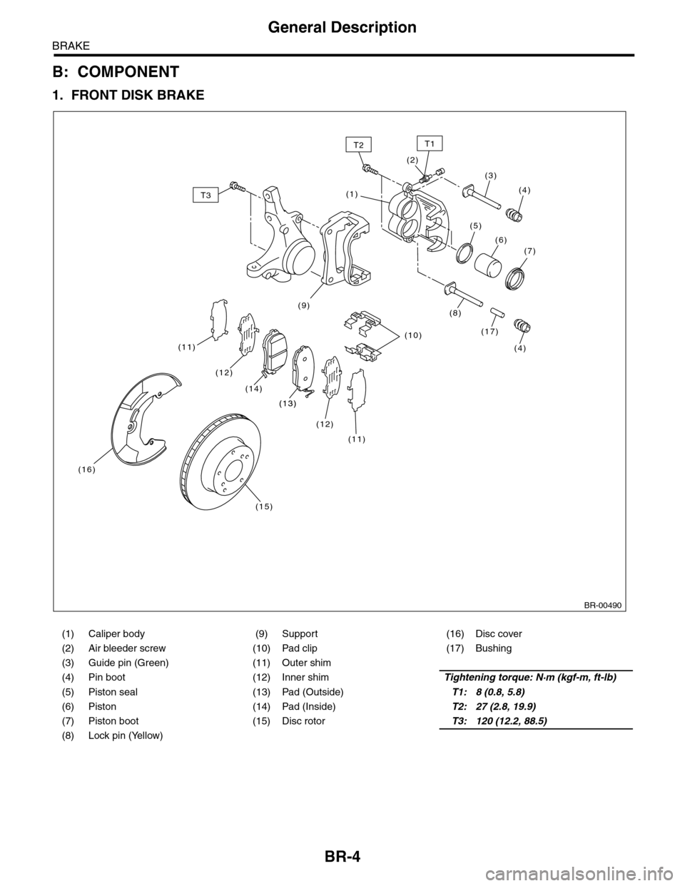
B: COMPONENT
1. FRONT DISK BRAKE
(1) Caliper body (9) Support (16) Disc cover
(2) Air bleeder screw (10) Pad clip (17) Bushing
(3) Guide pin (Green) (11) Outer shim
(4) Pin boot (12) Inner shimTightening torque: N·m (kgf-m, ft-lb)
(5) Piston seal (13) Pad (Outside)T1: 8 (0.8, 5.8)
(6) Piston (14) Pad (Inside)T2: 27 (2.8, 19.9)
(7) Piston boot (15) Disc rotorT3: 120 (12.2, 88.5)
(8) Lock pin (Yellow)
BR-00490
(1)
(2)
(3)
(4)
(4)
(17)(10)
(16)
(15)
(5)
(6)(7)
(8)
T2
T3
(11)
(11)
(12)
(12)
(13)
(14)
(13)
T1
(9)
Page 719 of 2453
BR-5
General Description
BRAKE
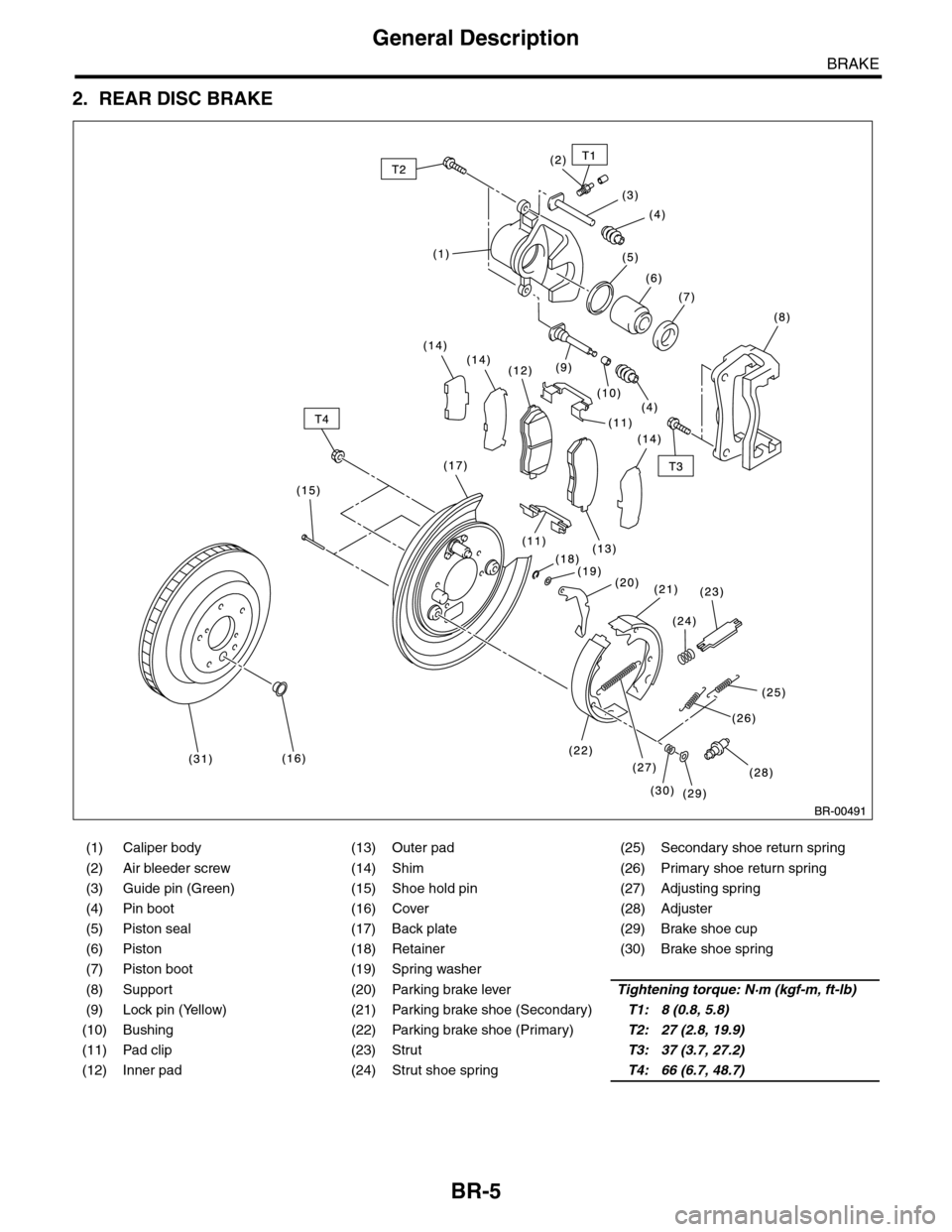
2. REAR DISC BRAKE
(1) Caliper body (13) Outer pad (25) Secondary shoe return spring
(2) Air bleeder screw (14) Shim (26) Primary shoe return spring
(3) Guide pin (Green) (15) Shoe hold pin (27) Adjusting spring
(4) Pin boot (16) Cover (28) Adjuster
(5) Piston seal (17) Back plate (29) Brake shoe cup
(6) Piston (18) Retainer (30) Brake shoe spring
(7) Piston boot (19) Spring washer
(8) Support (20) Parking brake leverTightening torque: N·m (kgf-m, ft-lb)
(9) Lock pin (Yellow) (21) Parking brake shoe (Secondary)T1: 8 (0.8, 5.8)
(10) Bushing (22) Parking brake shoe (Primary)T2: 27 (2.8, 19.9)
(11) Pad clip (23) StrutT3: 37 (3.7, 27.2)
(12) Inner pad (24) Strut shoe springT4: 66 (6.7, 48.7)
Page 720 of 2453
BR-6
General Description
BRAKE
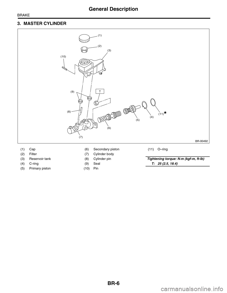
3. MASTER CYLINDER
(1) Cap (6) Secondary piston (11) O–ring
(2) Filter (7) Cylinder body
(3) Reservoir tank (8) Cylinder pinTightening torque: N·m (kgf-m, ft-lb)
(4) C-ring (9) SealT: 25 (2.5, 18.4)
(5) Primary piston (10) Pin
BR-00492
T
(1)
(2)
(3)
(7)
(8)
(9)
(10)
(4)(11)
(5)
(6)