SUBARU TRIBECA 2009 1.G Service Workshop Manual
Manufacturer: SUBARU, Model Year: 2009, Model line: TRIBECA, Model: SUBARU TRIBECA 2009 1.GPages: 2453, PDF Size: 46.32 MB
Page 701 of 2453
WW-6
Combination Switch (Wiper)
WIPER AND WASHER SYSTEMS
3. Combination Switch (Wiper)
A: REMOVAL
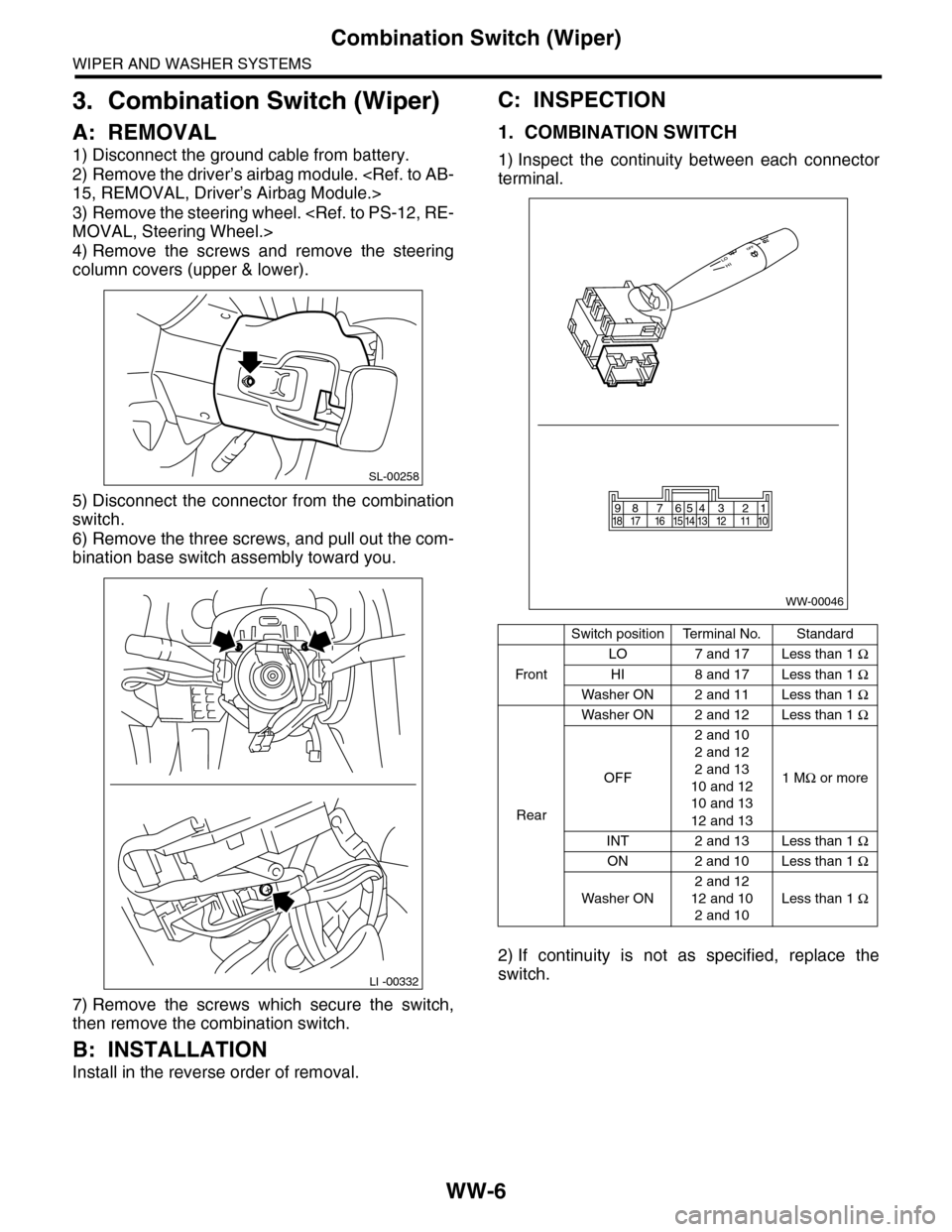
1) Disconnect the ground cable from battery.
2) Remove the driver’s airbag module.
3) Remove the steering wheel.
4) Remove the screws and remove the steering
column covers (upper & lower).
5) Disconnect the connector from the combination
switch.
6) Remove the three screws, and pull out the com-
bination base switch assembly toward you.
7) Remove the screws which secure the switch,
then remove the combination switch.
B: INSTALLATION
Install in the reverse order of removal.
C: INSPECTION
1. COMBINATION SWITCH
1) Inspect the continuity between each connector
terminal.
2) If continuity is not as specified, replace the
switch.
SL-00258
LI -00332
Switch positionTerminal No.Standard
Fr o n t
LO 7 and 17 Less than 1 Ω
HI 8 and 17 Less than 1 Ω
Washer ON 2 and 11 Less than 1 Ω
Rear
Washer ON 2 and 12 Less than 1 Ω
OFF
2 and 10
2 and 12
2 and 13
10 and 12
10 and 13
12 and 13
1 MΩ or more
INT 2 and 13 Less than 1 Ω
ON 2 and 10 Less than 1 Ω
Washer ON
2 and 12
12 and 10
2 and 10
Less than 1 Ω
WW-00046
87654321917 16 15 14 13 12 11 1018
Page 702 of 2453
WW-7
Combination Switch (Wiper)
WIPER AND WASHER SYSTEMS
2. FRONT WIPER
1) Check with Subaru Select Monitor
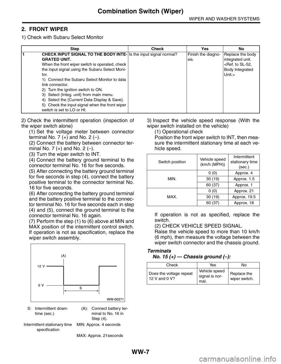
2) Check the intermittent operation (inspection of
the wiper switch alone)
(1) Set the voltage meter between connector
terminal No. 7 (+) and No. 2 (–).
(2) Connect the battery between connector ter-
minal No. 7 (+) and No. 2 (–).
(3) Turn the wiper switch to INT.
(4) Connect the battery ground terminal to the
connector terminal No. 16 for five seconds.
(5) After connecting the battery ground terminal
for five seconds in step (4), connect the battery
positive terminal to the connector terminal No.
16 for five seconds.
(6) After connecting the battery ground terminal
and the battery positive terminal to the connec-
tor terminal No. 16 for five seconds each in step
(4) and (5), connect the ground terminal to the
connector terminal No. 16 again.
(7) Perform the step (1) to (6) above at MIN and
MAX position of the intermittent control switch.
If operation is not as specification, replace the
wiper switch assembly.
3) Inspect the vehicle speed response (With the
wiper switch installed on the vehicle)
(1) Operational check
Position the front wiper switch to INT, then mea-
sure the intermittent stationary time at each ve-
hicle speed.
If operation is not as specified, replace the
switch.
(2) CHECK VEHICLE SPEED SIGNAL.
Raise the vehicle speed to more than 10 km/h
(6 mph), then measure the voltage between the
wiper switch connector and the chassis ground.
Terminals
No. 15 (+) — Chassis ground (–):
Step Check Yes No
1CHECK INPUT SIGNAL TO THE BODY INTE-
GRATED UNIT.
When the front wiper switch is operated, check
the input signal using the Subaru Select Moni-
tor.
1) Connect the Subaru Select Monitor to data
link connector.
2) Turn the ignition switch to ON.
3) Select {Integ. unit} from main menu.
4) Select the {Current Data Display & Save}.
5) Check the input signal when the front wiper
switch is set to LO or HI.
Is the input signal normal? Finish the diagno-
sis.
Replace the body
integrated unit.
Unit.>
S: Intermittent down-
time (sec.)
(A): Connect battery ter-
minal to No. 16 in
Step (4).
Intermittent stationary time
specification
MIN: Approx. 4 seconds
MAX: Approx. 21seconds
Switch positionVe h i c l e s p e e d
(km/h (MPH))
Intermittent
stationary time
(sec.)
MIN.
0 (0) Approx. 4
30 (19) Approx. 1.5
60 (37) Approx. 1
MAX.
0 (0) Approx. 21
30 (19) Approx. 19.5
60 (37) Approx. 18
Check Yes No
Does the voltage repeat
12 V and 0 V?
Ve h i c l e s p e e d
signal is nor-
mal.
Replace the
wiper switch.
Page 703 of 2453
WW-8
Combination Switch (Wiper)
WIPER AND WASHER SYSTEMS
(3) CHECK THE VEHICLE SPEED SIGNAL
HARNESS.
Measure the resistance between the wiper
switch connector and the VDC control module.
Terminals
Wiper switch connector No. 15 — VDC con-
trol module No. 33:
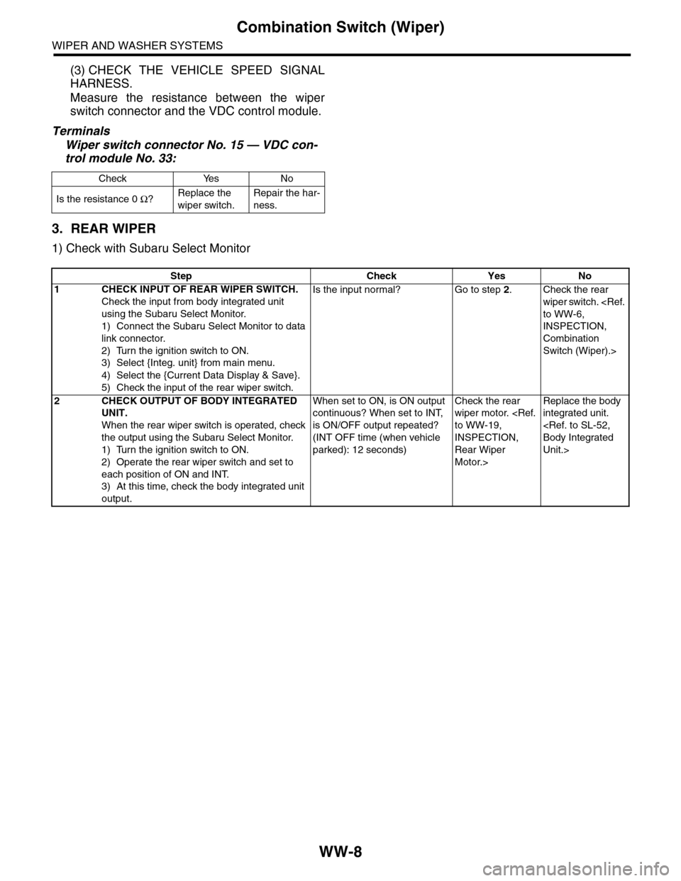
3. REAR WIPER
1) Check with Subaru Select Monitor
Check Yes No
Is the resistance 0 Ω?Replace the
wiper switch.
Repair the har-
ness.
Step Check Yes No
1 CHECK INPUT OF REAR WIPER SWITCH.
Check the input from body integrated unit
using the Subaru Select Monitor.
1) Connect the Subaru Select Monitor to data
link connector.
2) Turn the ignition switch to ON.
3) Select {Integ. unit} from main menu.
4) Select the {Current Data Display & Save}.
5) Check the input of the rear wiper switch.
Is the input normal? Go to step 2.Check the rear
wiper switch.
INSPECTION,
Combination
Switch (Wiper).>
2CHECK OUTPUT OF BODY INTEGRATED
UNIT.
When the rear wiper switch is operated, check
the output using the Subaru Select Monitor.
1) Turn the ignition switch to ON.
2) Operate the rear wiper switch and set to
each position of ON and INT.
3) At this time, check the body integrated unit
output.
When set to ON, is ON output
continuous? When set to INT,
is ON/OFF output repeated?
(INT OFF time (when vehicle
parked): 12 seconds)
Check the rear
wiper motor.
INSPECTION,
Rear Wiper
Motor.>
Replace the body
integrated unit.
Unit.>
Page 704 of 2453
WW-9
Combination Switch (Wiper)
WIPER AND WASHER SYSTEMS
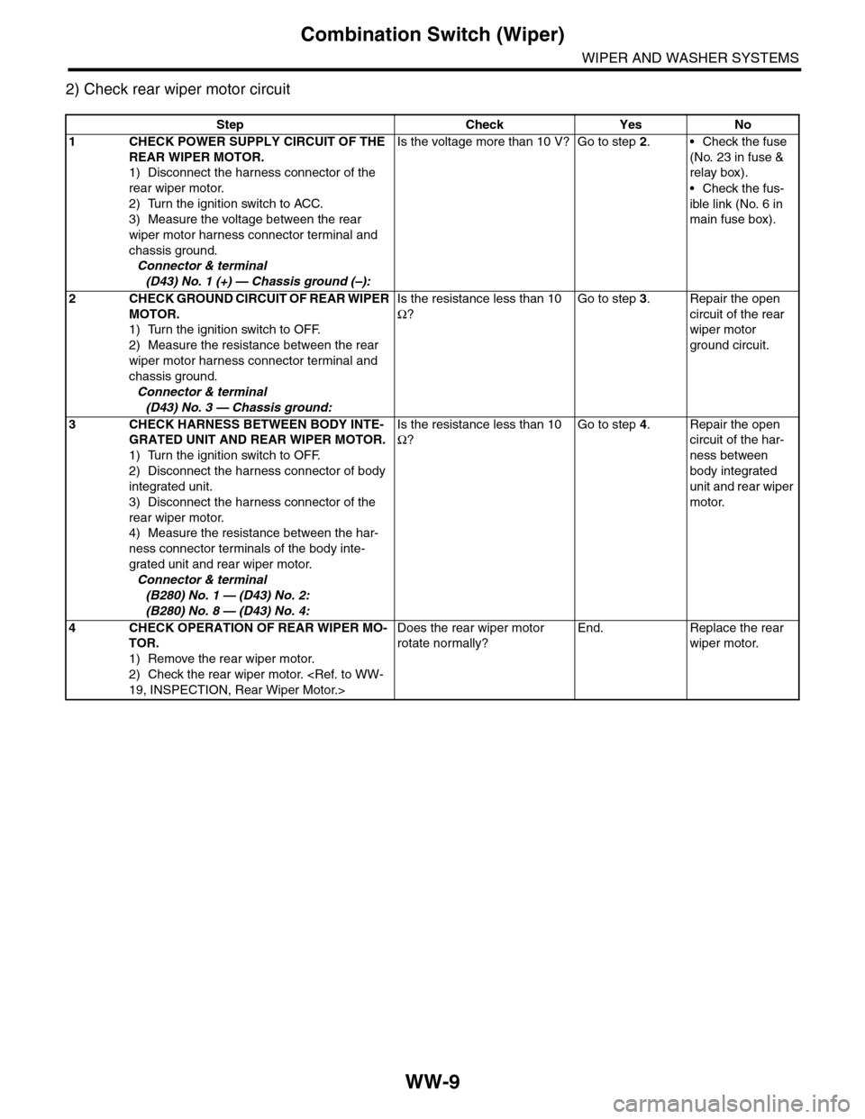
2) Check rear wiper motor circuit
Step Check Yes No
1CHECK POWER SUPPLY CIRCUIT OF THE
REAR WIPER MOTOR.
1) Disconnect the harness connector of the
rear wiper motor.
2) Turn the ignition switch to ACC.
3) Measure the voltage between the rear
wiper motor harness connector terminal and
chassis ground.
Connector & terminal
(D43) No. 1 (+) — Chassis ground (–):
Is the voltage more than 10 V? Go to step 2.•Check the fuse
(No. 23 in fuse &
relay box).
•Check the fus-
ible link (No. 6 in
main fuse box).
2CHECK GROUND CIRCUIT OF REAR WIPER
MOTOR.
1) Turn the ignition switch to OFF.
2) Measure the resistance between the rear
wiper motor harness connector terminal and
chassis ground.
Connector & terminal
(D43) No. 3 — Chassis ground:
Is the resistance less than 10
Ω?
Go to step 3.Repair the open
circuit of the rear
wiper motor
ground circuit.
3CHECK HARNESS BETWEEN BODY INTE-
GRATED UNIT AND REAR WIPER MOTOR.
1) Turn the ignition switch to OFF.
2) Disconnect the harness connector of body
integrated unit.
3) Disconnect the harness connector of the
rear wiper motor.
4) Measure the resistance between the har-
ness connector terminals of the body inte-
grated unit and rear wiper motor.
Connector & terminal
(B280) No. 1 — (D43) No. 2:
(B280) No. 8 — (D43) No. 4:
Is the resistance less than 10
Ω?
Go to step 4.Repair the open
circuit of the har-
ness between
body integrated
unit and rear wiper
motor.
4CHECK OPERATION OF REAR WIPER MO-
TOR.
1) Remove the rear wiper motor.
2) Check the rear wiper motor.
Does the rear wiper motor
rotate normally?
End. Replace the rear
wiper motor.
Page 705 of 2453
WW-10
Wiper Blade
WIPER AND WASHER SYSTEMS
4. Wiper Blade
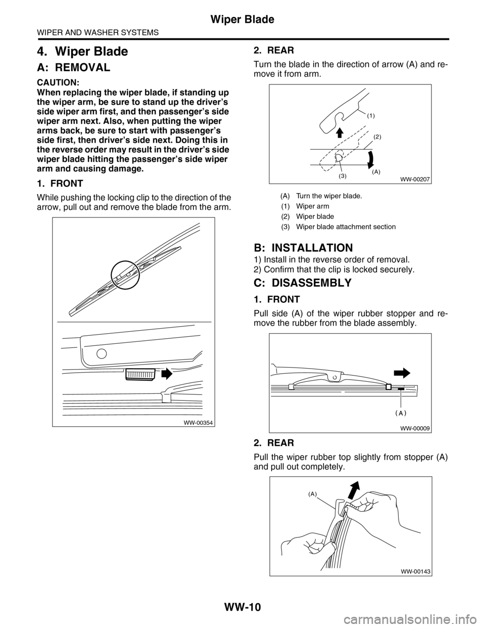
A: REMOVAL
CAUTION:
When replacing the wiper blade, if standing up
the wiper arm, be sure to stand up the driver’s
side wiper arm first, and then passenger’s side
wiper arm next. Also, when putting the wiper
arms back, be sure to start with passenger’s
side first, then driver’s side next. Doing this in
the reverse order may result in the driver’s side
wiper blade hitting the passenger’s side wiper
arm and causing damage.
1. FRONT
While pushing the locking clip to the direction of the
arrow, pull out and remove the blade from the arm.
2. REAR
Turn the blade in the direction of arrow (A) and re-
move it from arm.
B: INSTALLATION
1) Install in the reverse order of removal.
2) Confirm that the clip is locked securely.
C: DISASSEMBLY
1. FRONT
Pull side (A) of the wiper rubber stopper and re-
move the rubber from the blade assembly.
2. REAR
Pull the wiper rubber top slightly from stopper (A)
and pull out completely.
WW-00354
(A) Turn the wiper blade.
(1) Wiper arm
(2) Wiper blade
(3) Wiper blade attachment section
(1)
(2)
(3)(A)WW-00207
WW-00009
WW-00143
(A)
Page 706 of 2453
WW-11
Wiper Blade
WIPER AND WASHER SYSTEMS
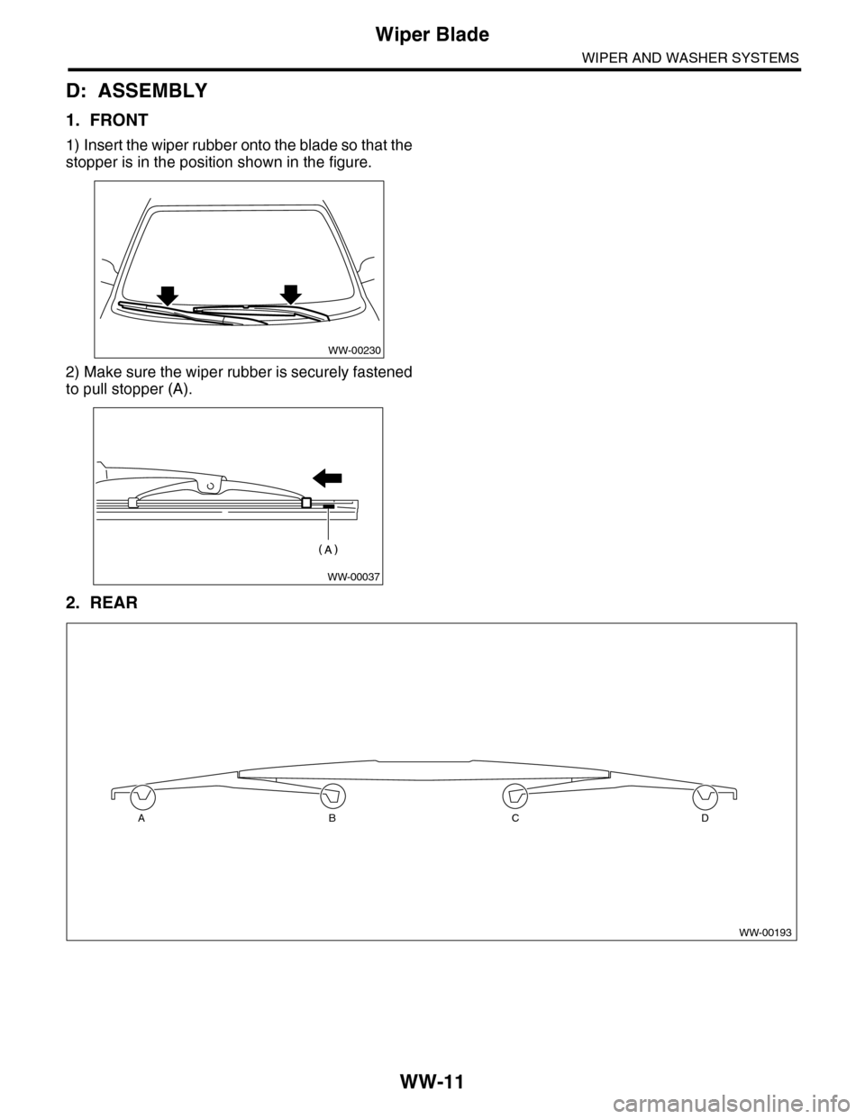
D: ASSEMBLY
1. FRONT
1) Insert the wiper rubber onto the blade so that the
stopper is in the position shown in the figure.
2) Make sure the wiper rubber is securely fastened
to pull stopper (A).
2. REAR
WW-00230
WW-00037
WW-00193
ABCD
Page 707 of 2453
WW-12
Wiper Blade
WIPER AND WASHER SYSTEMS
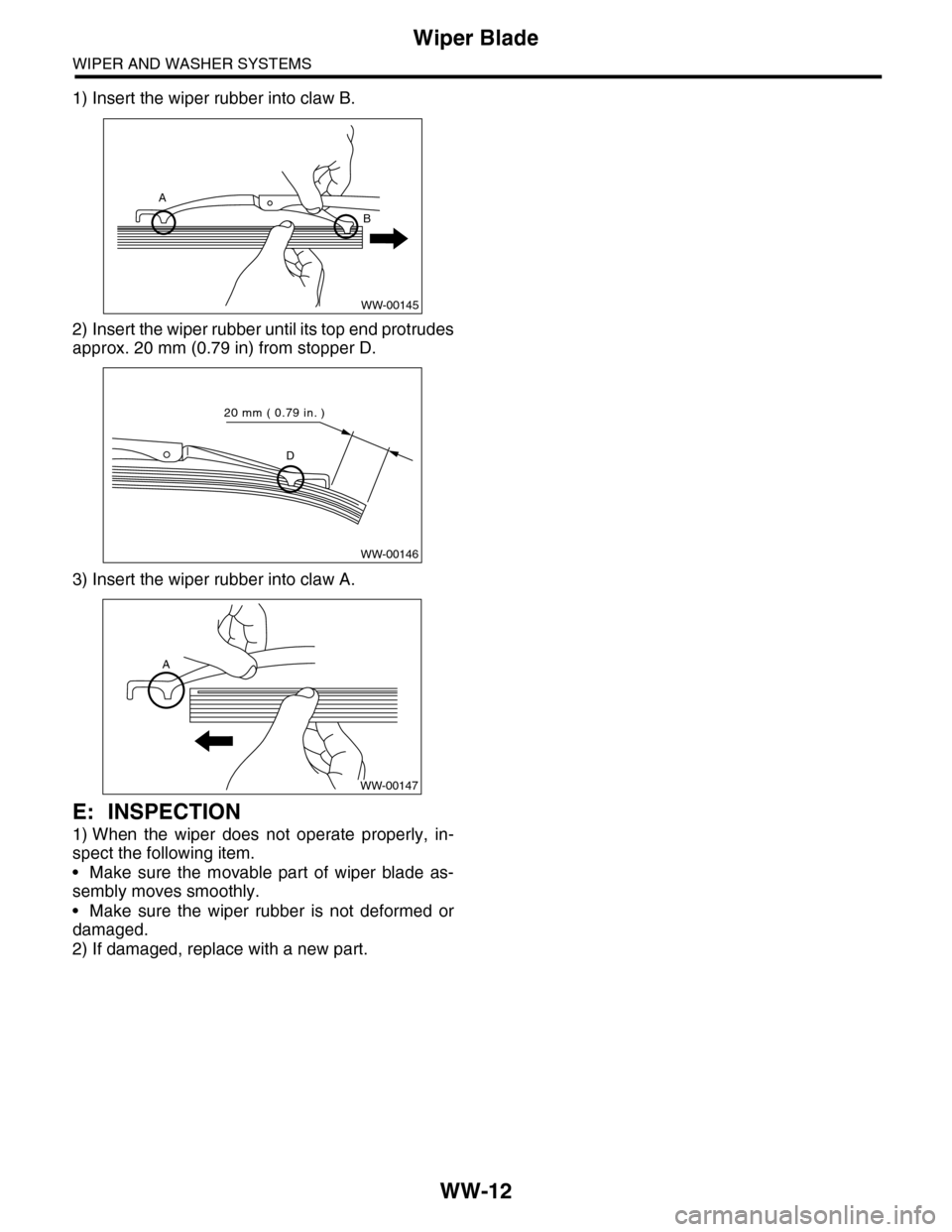
1) Insert the wiper rubber into claw B.
2) Insert the wiper rubber until its top end protrudes
approx. 20 mm (0.79 in) from stopper D.
3) Insert the wiper rubber into claw A.
E: INSPECTION
1) When the wiper does not operate properly, in-
spect the following item.
•Make sure the movable part of wiper blade as-
sembly moves smoothly.
•Make sure the wiper rubber is not deformed or
damaged.
2) If damaged, replace with a new part.
WW-00145
A
B
WW-00146
D
20 mm ( 0.79 in. )
A
WW-00147
Page 708 of 2453
WW-13
Washer Tank and Motor
WIPER AND WASHER SYSTEMS
5. Washer Tank and Motor
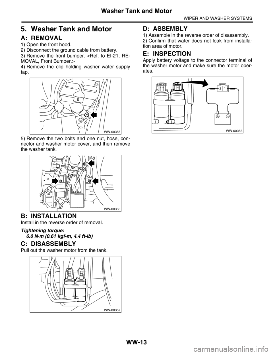
A: REMOVAL
1) Open the front hood.
2) Disconnect the ground cable from battery.
3) Remove the front bumper.
4) Remove the clip holding washer water supply
tap.
5) Remove the two bolts and one nut, hose, con-
nector and washer motor cover, and then remove
the washer tank.
B: INSTALLATION
Install in the reverse order of removal.
Tightening torque:
6.0 N·m (0.61 kgf-m, 4.4 ft-lb)
C: DISASSEMBLY
Pull out the washer motor from the tank.
D: ASSEMBLY
1) Assemble in the reverse order of disassembly.
2) Confirm that water does not leak from installa-
tion area of motor.
E: INSPECTION
Apply battery voltage to the connector terminal of
the washer motor and make sure the motor oper-
ates.
WW-00355
WW-00356
WW-00357
WW-00358
12
Page 709 of 2453
WW-14
Wiper Relay Unit
WIPER AND WASHER SYSTEMS
6. Wiper Relay Unit
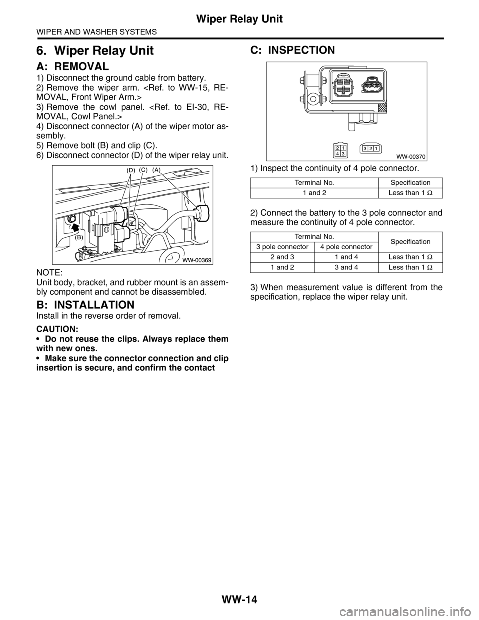
A: REMOVAL
1) Disconnect the ground cable from battery.
2) Remove the wiper arm.
3) Remove the cowl panel.
4) Disconnect connector (A) of the wiper motor as-
sembly.
5) Remove bolt (B) and clip (C).
6) Disconnect connector (D) of the wiper relay unit.
NOTE:
Unit body, bracket, and rubber mount is an assem-
bly component and cannot be disassembled.
B: INSTALLATION
Install in the reverse order of removal.
CAUTION:
•Do not reuse the clips. Always replace them
with new ones.
•Make sure the connector connection and clip
insertion is secure, and confirm the contact
C: INSPECTION
1) Inspect the continuity of 4 pole connector.
2) Connect the battery to the 3 pole connector and
measure the continuity of 4 pole connector.
3) When measurement value is different from the
specification, replace the wiper relay unit.
Te r m i n a l N o . S p e c i f i c a t i o n
1 and 2 Less than 1 Ω
Te r m i n a l N o .Specification3 pole connector 4 pole connector
2 and 3 1 and 4 Less than 1 Ω
1 and 2 3 and 4 Less than 1 Ω
Page 710 of 2453
WW-15
Front Wiper Arm
WIPER AND WASHER SYSTEMS
7. Front Wiper Arm
A: REMOVAL
CAUTION:
When standing up the wiper arm, be sure to
stand up the driver’s side wiper arm first, and
then passenger’s side wiper arm next. Also,
when putting the wiper arms back, be sure to
start with passenger’s side first, then driver’s
side next. Doing this in the reverse order may
cause the driver’s side wiper blade to hit the
passenger’s side wiper arm and cause damage.
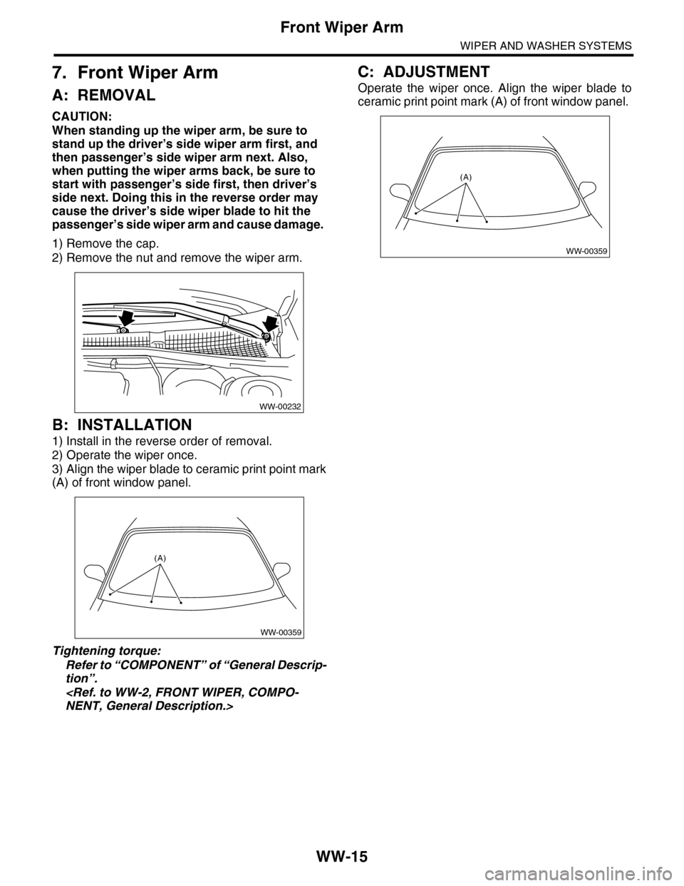
1) Remove the cap.
2) Remove the nut and remove the wiper arm.
B: INSTALLATION
1) Install in the reverse order of removal.
2) Operate the wiper once.
3) Align the wiper blade to ceramic print point mark
(A) of front window panel.
Tightening torque:
Refer to “COMPONENT” of “General Descrip-
tion”.
C: ADJUSTMENT
Operate the wiper once. Align the wiper blade to
ceramic print point mark (A) of front window panel.
WW-00232
WW-00359
(A)
WW-00359
(A)