fuse SUBARU TRIBECA 2009 1.G Service Manual PDF
[x] Cancel search | Manufacturer: SUBARU, Model Year: 2009, Model line: TRIBECA, Model: SUBARU TRIBECA 2009 1.GPages: 2453, PDF Size: 46.32 MB
Page 1166 of 2453
EN(H6DO)(diag)-5
General Description
ENGINE (DIAGNOSTICS)
3. General Description
A: CAUTION
1) Airbag system wiring harness is routed near the
ECM, main relay and fuel pump relay.
CAUTION:
•All airbag system wiring harnesses and con-
nectors are colored yellow. Do not use electri-
cal test equipment on these circuits.
•Be careful not to damage the airbag system
wiring harness when servicing the ECM, TCM,
main relay and fuel pump relay.
2) Never connect the battery in reverse polarity.
•The ECM will be destroyed instantly.
•The fuel injector and other parts will be dam-
aged.
3) Do not disconnect the battery terminals while the
engine is running.
A large counter electromotive force will be generat-
ed in the generator, and this voltage may damage
electronic parts such as ECM etc.
4) Before disconnecting the connectors of each
sensor and ECM, be sure to turn the ignition switch
to OFF. Perform the clear memory mode after con-
necting the connectors.
5) Poor contact has been identified as a primary
cause of this problem. Measure the voltage or re-
sistance of individual sensor or all electrical control
modules using a tapered pin with a diameter of less
than 0.64 mm (0.025 in). Do not insert the pin more
than 5 mm (0.20 in) into the part.
6) Remove the ECM from the located position after
disconnecting two cables on battery.
Otherwise, the ECM may be damaged.
CAUTION:
When replacing the ECM, be careful not to use
the wrong spec. ECM to avoid any damage on
the fuel injection system.
7) Connectors of each sensor in the engine com-
partment and the harness connectors on the en-
gine side and body side are all designed to be
waterproof. Even if the connectors are waterproof,
take care not to allow water to get into them when
washing the vehicle, or when servicing the vehicle
in rainy weather.
8) Use ECM mounting stud bolts as the grounding
point to chassis when measuring voltage and resis-
tance in the passenger compartment.
9) Use the engine ground terminal or engine as-
sembly as the grounding point to chassis when
measuring the voltage and resistance in engine
compartment.
10) Every MFI-related part is a precision part. Do
not drop them.
11) Observe the following cautions when installing
a radio in MFI equipped models.
CAUTION:
•The antenna must be kept as far apart as pos-
sible from control unit. (The ECM is located un-
der the steering column, inside of the
instrument panel lower trim panel.)
•The antenna feeder must be placed as far apart
as possible from the ECM and MFI harness.
•Carefully adjust the antenna for correct
matching.
•When mounting a large power type radio, pay
special attention to the three items mentioned
above.
•Incorrect installation of the radio may affect
the operation of ECM.
12) Release the pressure in the fuel system before
disconnecting the fuel hose. If engine starts during
this operation, run it until it stops.
13) For the model with ABS, the ABS warning light
may illuminate when performing driving test with
jacked-up or lifted-up condition, but this is not a
system malfunction. The reason for this is the
speed difference between the front and rear
wheels. After diagnosis of engine control system,
perform the ABS memory clear procedure of self-
diagnosis function.
B: INSPECTION
Before performing diagnostics, check the following
item which might affect engine problems.
1. BATTERY
1) Measure the battery voltage and specific gravity
of electrolyte.
Standard voltage: 12 V
Specific gravity: Above 1.260
2) Check the condition of the main and other fuses,
and harnesses and connectors. Also check for
proper grounding.
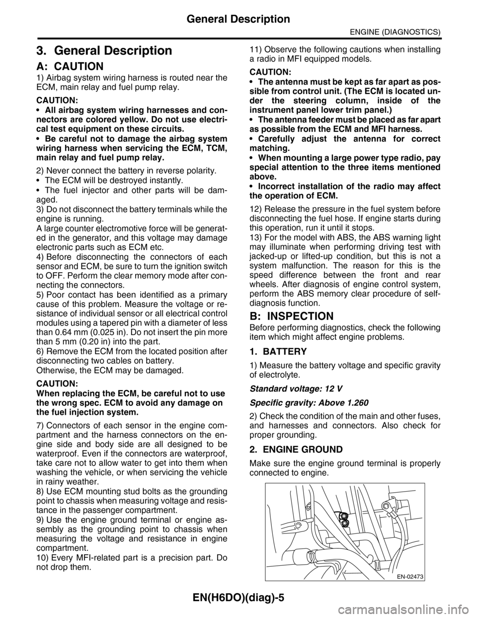
2. ENGINE GROUND
Make sure the engine ground terminal is properly
connected to engine.
EN-02473
Page 1212 of 2453
EN(H6DO)(diag)-51
Malfunction Indicator Light
ENGINE (DIAGNOSTICS)
3CHECK ECM CONNECTOR.
Check the connection of ECM connector.
Is the ECM connector correctly
connected?
Replace the ECM.
Engine Control
Module (ECM).>
Repair the con-
nection of ECM
connector.
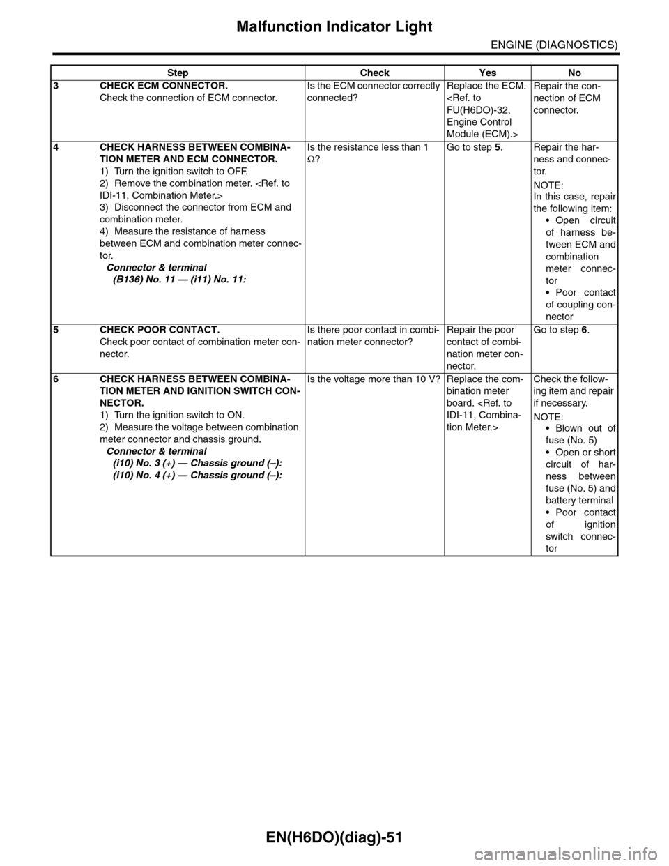
4CHECK HARNESS BETWEEN COMBINA-
TION METER AND ECM CONNECTOR.
1) Turn the ignition switch to OFF.
2) Remove the combination meter.
3) Disconnect the connector from ECM and
combination meter.
4) Measure the resistance of harness
between ECM and combination meter connec-
tor.
Connector & terminal
(B136) No. 11 — (i11) No. 11:
Is the resistance less than 1
Ω?
Go to step 5.Repair the har-
ness and connec-
tor.
NOTE:In this case, repair
the following item:
•Open circuit
of harness be-
tween ECM and
combination
meter connec-
tor
•Poor contact
of coupling con-
nector
5CHECK POOR CONTACT.
Check poor contact of combination meter con-
nector.
Is there poor contact in combi-
nation meter connector?
Repair the poor
contact of combi-
nation meter con-
nector.
Go to step 6.
6CHECK HARNESS BETWEEN COMBINA-
TION METER AND IGNITION SWITCH CON-
NECTOR.
1) Turn the ignition switch to ON.
2) Measure the voltage between combination
meter connector and chassis ground.
Connector & terminal
(i10) No. 3 (+) — Chassis ground (–):
(i10) No. 4 (+) — Chassis ground (–):
Is the voltage more than 10 V? Replace the com-
bination meter
board.
tion Meter.>
Check the follow-
ing item and repair
if necessary.
NOTE:
•Blown out of
fuse (No. 5)
•Open or short
circuit of har-
ness between
fuse (No. 5) and
battery terminal
•Poor contact
of ignition
switch connec-
tor
Step Check Yes No
Page 1220 of 2453
EN(H6DO)(diag)-59
Diagnostics for Engine Starting Failure
ENGINE (DIAGNOSTICS)
Step Check Yes No
1CHECK BATTERY.
Check the battery voltage.
Is the voltage more than 12 V? Go to step 2.Charge or replace
the battery.
2CHECK OPERATION OF STARTER MOTOR.Does the starter motor oper-
ate?
Go to step 3.Go to step 4.
3CHECK DTC.Is DTC displayed?
TION, Read Diagnostic Trouble
Code (DTC).>
Check the appro-
priate DTC using
the List of Diag-
nostic Trouble
Code (DTC).
EN(H6DO)(diag)-
69, List of Diag-
nostic Trouble
Code (DTC).>
Repair poor con-
tact in ECM con-
nector.
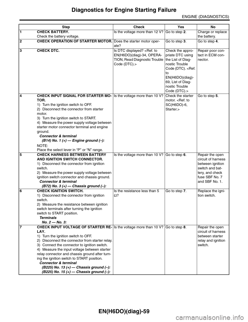
4CHECK INPUT SIGNAL FOR STARTER MO-
TOR.
1) Turn the ignition switch to OFF.
2) Disconnect the connector from starter
motor.
3) Turn the ignition switch to START.
4) Measure the power supply voltage between
starter motor connector terminal and engine
ground.
Connector & terminal
(B14) No. 1 (+) — Engine ground (–):
NOTE:Place the select lever in “P” or “N” range.
Is the voltage more than 10 V? Check the starter
motor.
Starter.>
Go to step 5.
5CHECK HARNESS BETWEEN BATTERY
AND IGNITION SWITCH CONNECTOR.
1) Disconnect the connector from ignition
switch.
2) Measure the power supply voltage between
ignition switch connector and chassis ground.
Connector & terminal
(B72) No. 3 (+) — Chassis ground (–):
Is the voltage more than 10 V? Go to step 6.Repair the open
circuit of harness
between ignition
switch and bat-
tery, and check
fuse SBF No. 7
and SBF No. 1.
6CHECK IGNITION SWITCH.
1) Disconnect the connector from ignition
switch.
2) Measure the resistance between ignition
switch terminals after turning the ignition
switch to START position.
Te r m i n a l s
No. 2 — No. 3:
Is the resistance less than 5
Ω?
Go to step 7.Replace the igni-
tion switch.
7CHECK INPUT VOLTAGE OF STARTER RE-
LAY.
1) Turn the ignition switch to OFF.
2) Disconnect the connector from starter relay.
3) Connect the connector to ignition switch.
4) Measure the input voltage between starter
relay connector and chassis ground after turn-
ing the ignition switch to START position.
Connector & terminal
(B225) No. 13 (+) — Chassis ground (–):
(B225) No. 15 (+) — Chassis ground (–):
Is the voltage more than 10 V? Go to step 8.Repair the open
circuit of harness
between starter
relay and ignition
switch.
Page 1480 of 2453
EN(H6DO)(diag)-319
Diagnostic Procedure with Diagnostic Trouble Code (DTC)
ENGINE (DIAGNOSTICS)
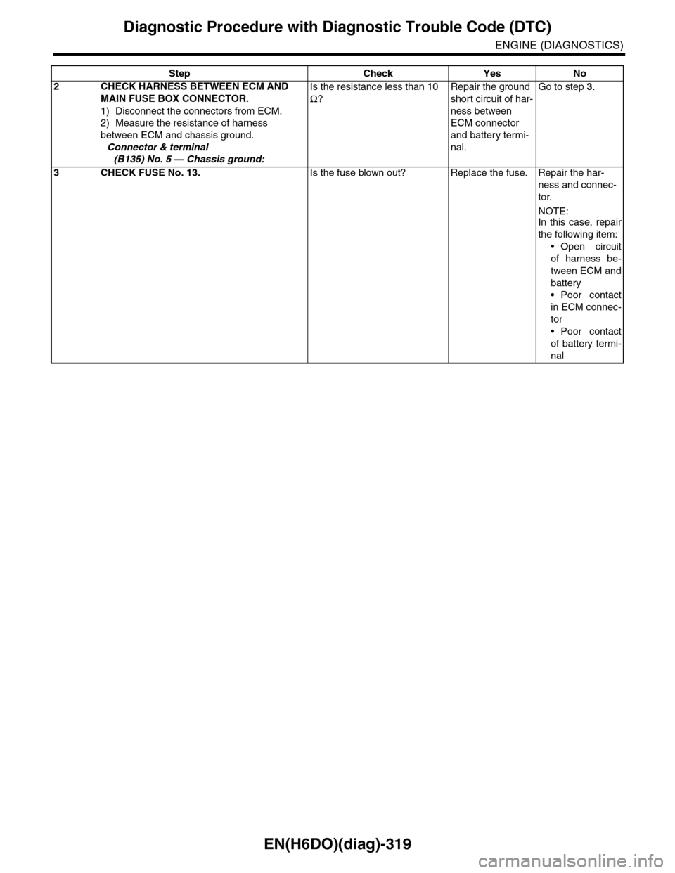
2CHECK HARNESS BETWEEN ECM AND
MAIN FUSE BOX CONNECTOR.
1) Disconnect the connectors from ECM.
2) Measure the resistance of harness
between ECM and chassis ground.
Connector & terminal
(B135) No. 5 — Chassis ground:
Is the resistance less than 10
Ω?
Repair the ground
short circuit of har-
ness between
ECM connector
and battery termi-
nal.
Go to step 3.
3CHECK FUSE No. 13.Is the fuse blown out? Replace the fuse. Repair the har-
ness and connec-
tor.
NOTE:In this case, repair
the following item:
•Open circuit
of harness be-
tween ECM and
battery
•Poor contact
in ECM connec-
tor
•Poor contact
of battery termi-
nal
Step Check Yes No
Page 1576 of 2453
FU(H6DO)-15
Intake Manifold
FUEL INJECTION (FUEL SYSTEMS)
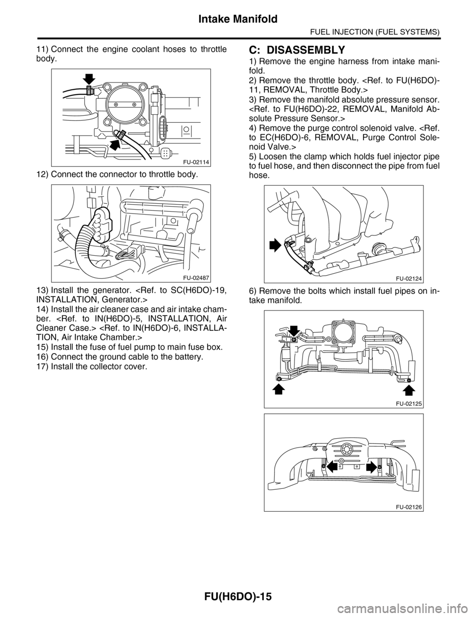
11) Connect the engine coolant hoses to throttle
body.
12) Connect the connector to throttle body.
13) Install the generator.
14) Install the air cleaner case and air intake cham-
ber.
15) Install the fuse of fuel pump to main fuse box.
16) Connect the ground cable to the battery.
17) Install the collector cover.
C: DISASSEMBLY
1) Remove the engine harness from intake mani-
fold.
2) Remove the throttle body.
3) Remove the manifold absolute pressure sensor.
4) Remove the purge control solenoid valve.
noid Valve.>
5) Loosen the clamp which holds fuel injector pipe
to fuel hose, and then disconnect the pipe from fuel
hose.
6) Remove the bolts which install fuel pipes on in-
take manifold.
FU-02114
FU-02487FU-02124
FU-02125
FU-02126
Page 1598 of 2453
FU(H6DO)-37
Fuel
FUEL INJECTION (FUEL SYSTEMS)
21.Fuel
A: PROCEDURE
1. RELEASING OF FUEL PRESSURE
WARNING:
•Place “NO FIRE” signs near the working area.
•Be careful not to spill fuel on the floor.
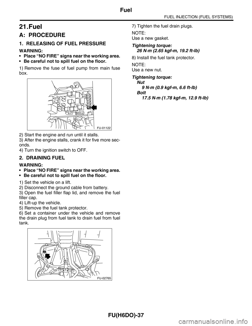
1) Remove the fuse of fuel pump from main fuse
box.
2) Start the engine and run until it stalls.
3) After the engine stalls, crank it for five more sec-
onds.
4) Turn the ignition switch to OFF.
2. DRAINING FUEL
WARNING:
•Place “NO FIRE” signs near the working area.
•Be careful not to spill fuel on the floor.
1) Set the vehicle on a lift.
2) Disconnect the ground cable from battery.
3) Open the fuel filler flap lid, and remove the fuel
filler cap.
4) Lift-up the vehicle.
5) Remove the fuel tank protector.
6) Set a container under the vehicle and remove
the drain plug from fuel tank to drain fuel from fuel
tank.
7) Tighten the fuel drain plugs.
NOTE:
Use a new gasket.
Tightening torque:
26 N·m (2.65 kgf-m, 19.2 ft-lb)
8) Install the fuel tank protector.
NOTE:
Use a new nut.
Tightening torque:
Nut
9 N·m (0.9 kgf-m, 6.6 ft-lb)
Bolt
17.5 N·m (1.78 kgf-m, 12.9 ft-lb)
FU-01122
FU-02765
Page 1601 of 2453
FU(H6DO)-40
Fuel Tank
FUEL INJECTION (FUEL SYSTEMS)
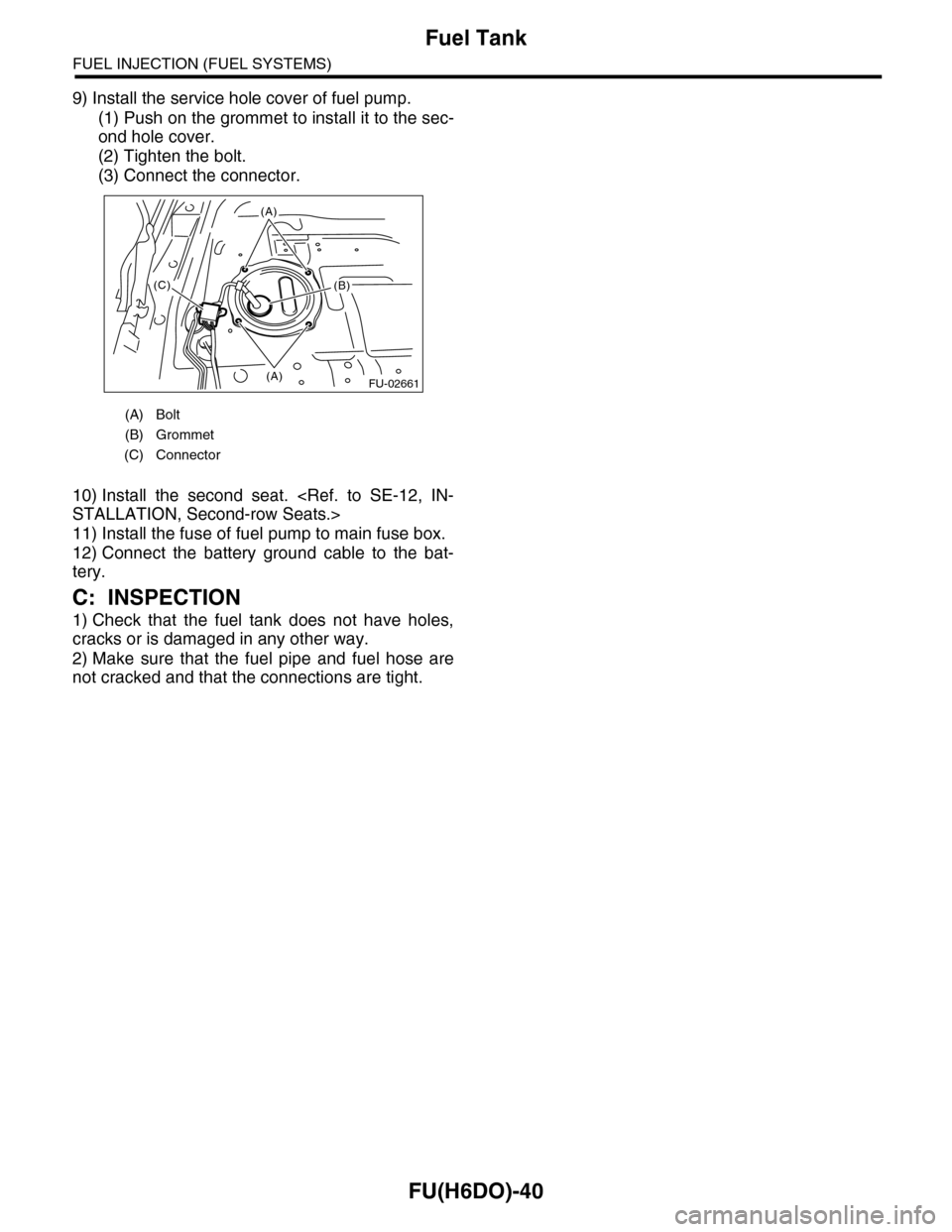
9) Install the service hole cover of fuel pump.
(1) Push on the grommet to install it to the sec-
ond hole cover.
(2) Tighten the bolt.
(3) Connect the connector.
10) Install the second seat.
11) Install the fuse of fuel pump to main fuse box.
12) Connect the battery ground cable to the bat-
tery.
C: INSPECTION
1) Check that the fuel tank does not have holes,
cracks or is damaged in any other way.
2) Make sure that the fuel pipe and fuel hose are
not cracked and that the connections are tight.
(A) Bolt
(B) Grommet
(C) Connector
FU-02661(A)
(A)
(B)(C)
Page 1892 of 2453

ME(H6DO)-26
Fuel Pressure
MECHANICAL
7. Fuel Pressure
A: INSPECTION
WARNING:
Before removing the fuel pressure gauge, re-
lease the fuel pressure.
1) Release the fuel pressure.
2) Disconnect the fuel delivery hose and connect
fuel pressure gauge.
(1) Disconnect the fuel delivery hose using the
ST1.
ST1 42099AE000 CONNECTOR REMOVER
(2) Connect the fuel pressure meter using the
ST2 and ST3.
NOTE:
ST2 is a genuine Subaru part.
ST2 42075AG690 FUEL HOSE
ST3 18471AA000 FUEL PIPE ADAPTER
3) Install the fuse of fuel pump to main fuse box.
4) Start the engine.
5) Measure the fuel pressure after warming up the
engine.
Fuel pressure:
Standard: 338 — 348 kPa (3.4 — 3.5 kgf/cm2,
49 — 50.5 psi)
NOTE:
The fuel pressure gauge registers 10 to 20 kPa (0.1
to 0.2 kgf/cm2, 1 to 3 psi) higher than standard val-
ues during high-altitude operations.
(A) ST 2
(B) ST 3
ME-02666
(A)
(B)
FU-01122
Page 1929 of 2453
ME(H6DO)-63
Cylinder Block
MECHANICAL
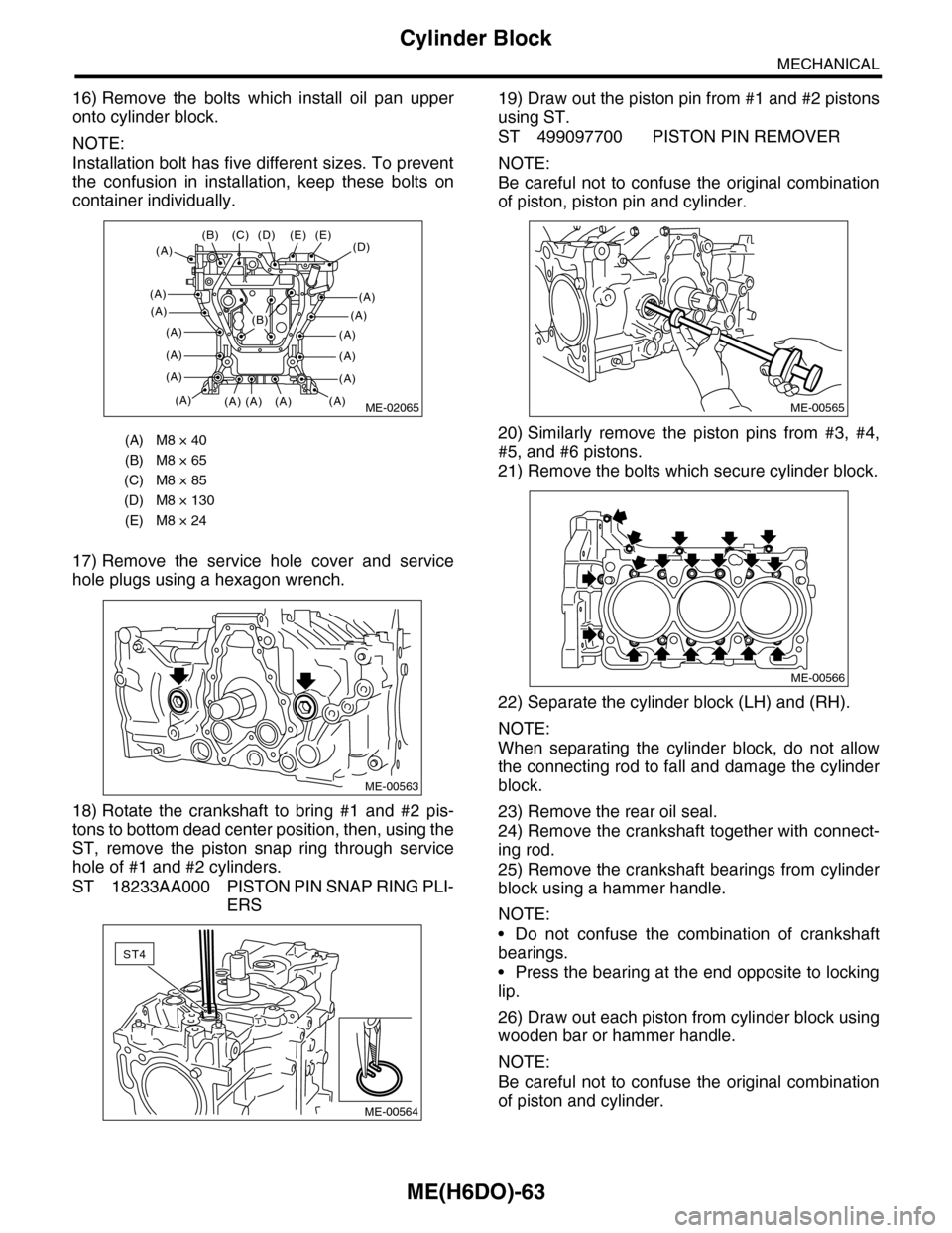
16) Remove the bolts which install oil pan upper
onto cylinder block.
NOTE:
Installation bolt has five different sizes. To prevent
the confusion in installation, keep these bolts on
container individually.
17) Remove the service hole cover and service
hole plugs using a hexagon wrench.
18) Rotate the crankshaft to bring #1 and #2 pis-
tons to bottom dead center position, then, using the
ST, remove the piston snap ring through service
hole of #1 and #2 cylinders.
ST 18233AA000 PISTON PIN SNAP RING PLI-
ERS
19) Draw out the piston pin from #1 and #2 pistons
using ST.
ST 499097700 PISTON PIN REMOVER
NOTE:
Be careful not to confuse the original combination
of piston, piston pin and cylinder.
20) Similarly remove the piston pins from #3, #4,
#5, and #6 pistons.
21) Remove the bolts which secure cylinder block.
22) Separate the cylinder block (LH) and (RH).
NOTE:
When separating the cylinder block, do not allow
the connecting rod to fall and damage the cylinder
block.
23) Remove the rear oil seal.
24) Remove the crankshaft together with connect-
ing rod.
25) Remove the crankshaft bearings from cylinder
block using a hammer handle.
NOTE:
•Do not confuse the combination of crankshaft
bearings.
•Press the bearing at the end opposite to locking
lip.
26) Draw out each piston from cylinder block using
wooden bar or hammer handle.
NOTE:
Be careful not to confuse the original combination
of piston and cylinder.
(A) M8 × 40
(B) M8 × 65
(C) M8 × 85
(D) M8 × 130
(E) M8 × 24
ME-02065
(D)(E)
(A)
(A)
(A)
(A)
(A)
(A)
(A)
(E)
(A)(A)(A)
(C)(B)
(A)
(D)
(A)
(A)
(A)
(A)
(A)
(B)
ME-00563
ST4
ME-00564
ME-00565
ME-00566
Page 2144 of 2453
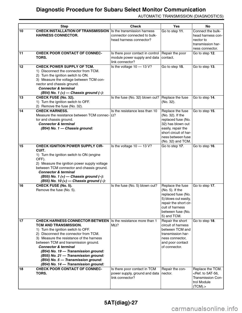
5AT(diag)-27
Diagnostic Procedure for Subaru Select Monitor Communication
AUTOMATIC TRANSMISSION (DIAGNOSTICS)
10 CHECK INSTALLATION OF TRANSMISSION
HARNESS CONNECTOR.
Is the transmission harness
connector connected to bulk-
head harness connector?
Go to step 11.Connect the bulk-
head harness con-
nector to
transmission har-
ness connector.
11 CHECK POOR CONTACT OF CONNEC-
TORS.
Is there poor contact in control
module power supply and data
link connector?
Repair the poor
contact.
Go to step 12.
12 CHECK POWER SUPPLY OF TCM.
1) Disconnect the connector from TCM.
2) Turn the ignition switch to ON.
3) Measure the voltage between TCM con-
nector and chassis ground.
Connector & terminal
(B54) No. 1 (+) — Chassis ground (–):
Is the voltage 10 — 13 V? Go to step 15.Go to step 13.
13 CHECK FUSE (No. 32).
1) Turn the ignition switch to OFF.
2) Remove the fuse (No. 32).
Is the fuse (No. 32) blown out? Replace the fuse
(No. 32).
Go to step 14.
14 CHECK HARNESS.
Measure the resistance between TCM connec-
tor and chassis ground.
Connector & terminal
(B54) No. 1 — Chassis ground:
Is the resistance less than 10
Ω?
Replace the fuse
(No. 32). If the
replaced fuse (No.
32) has blown out
easily, repair the
short circuit of har-
ness between fuse
(No. 32) and TCM.
Go to step 15.
15 CHECK IGNITION POWER SUPPLY CIR-
CUIT.
1) Turn the ignition switch to ON (engine
OFF).
2) Measure the ignition power supply voltage
between TCM connector and chassis ground.
Connector & terminal
(B55) No. 1 (+) — Chassis ground (–):
(B55) No. 10 (+) — Chassis ground (–):
Is the voltage 10 — 13 V? Go to step 17.Go to step 16.
16 CHECK FUSE (No. 5).
Remove the fuse (No. 5).
Is the fuse (No. 5) blown out? Replace the fuse
(No. 5). If the
replaced fuse (No.
5) blows out easily,
repair the short cir-
cuit of harness
between fuse (No.
5) and TCM.
Go to step 17.
17 CHECK HARNESS CONNECTOR BETWEEN
TCM AND TRANSMISSION.
1) Turn the ignition switch to OFF.
2) Disconnect the connector from TCM.
3) Measure the resistance of the harness
between TCM and transmission ground.
Connector & terminal
(B54) No. 19 — Transmission ground:
(B55) No. 21 — Transmission ground:
(B54) No. 5 — Transmission ground:
(B54) No. 14 — Transmission ground:
Is the resistance more than 1
MΩ?
Repair the short
circuit of harness
between TCM and
transmission har-
ness connector,
and poor contact
of connector.
Go to step 18.
18 CHECK POOR CONTACT OF CONNEC-
TORS.
Is there poor contact in TCM
power supply, ground and data
link connector?
Repair the con-
nector.
Replace the TCM.
trol Module
(TCM).>
Step Check Yes No