fuse SUBARU TRIBECA 2009 1.G Service Repair Manual
[x] Cancel search | Manufacturer: SUBARU, Model Year: 2009, Model line: TRIBECA, Model: SUBARU TRIBECA 2009 1.GPages: 2453, PDF Size: 46.32 MB
Page 700 of 2453
WW-5
Wiper and Washer System
WIPER AND WASHER SYSTEMS
2. Wiper and Washer System
A: WIRING DIAGRAM
1. WIPER AND WASHER (FRONT)
2. WIPER AND WASHER (REAR)
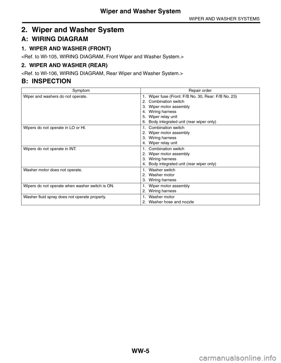
B: INSPECTION
Symptom Repair order
Wiper and washers do not operate. 1. Wiper fuse (Front: F/B No. 30, Rear : F/B No. 23)
2. Combination switch
3. Wiper motor assembly
4. Wiring harness
5. Wiper relay unit
6. Body integrated unit (rear wiper only)
Wipers do not operate in LO or HI. 1. Combination switch
2. Wiper motor assembly
3. Wiring harness
4. Wiper relay unit
Wipers do not operate in INT. 1. Combination switch
2. Wiper motor assembly
3. Wiring harness
4. Body integrated unit (rear wiper only)
Wa sh e r mo to r do e s n ot o pe ra t e. 1 . Wa sh e r swit c h
2. Washer motor
3. Wiring harness
Wipers do not operate when washer switch is ON. 1. Wiper motor assembly
2. Wiring harness
Wa sh e r fl u id sp ray do e s n ot op e ra te pr o p er l y. 1 . Wa sh e r m ot o r
2. Washer hose and nozzle
Page 704 of 2453
WW-9
Combination Switch (Wiper)
WIPER AND WASHER SYSTEMS
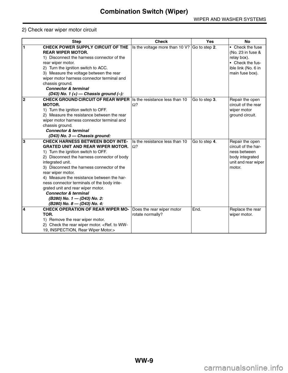
2) Check rear wiper motor circuit
Step Check Yes No
1CHECK POWER SUPPLY CIRCUIT OF THE
REAR WIPER MOTOR.
1) Disconnect the harness connector of the
rear wiper motor.
2) Turn the ignition switch to ACC.
3) Measure the voltage between the rear
wiper motor harness connector terminal and
chassis ground.
Connector & terminal
(D43) No. 1 (+) — Chassis ground (–):
Is the voltage more than 10 V? Go to step 2.•Check the fuse
(No. 23 in fuse &
relay box).
•Check the fus-
ible link (No. 6 in
main fuse box).
2CHECK GROUND CIRCUIT OF REAR WIPER
MOTOR.
1) Turn the ignition switch to OFF.
2) Measure the resistance between the rear
wiper motor harness connector terminal and
chassis ground.
Connector & terminal
(D43) No. 3 — Chassis ground:
Is the resistance less than 10
Ω?
Go to step 3.Repair the open
circuit of the rear
wiper motor
ground circuit.
3CHECK HARNESS BETWEEN BODY INTE-
GRATED UNIT AND REAR WIPER MOTOR.
1) Turn the ignition switch to OFF.
2) Disconnect the harness connector of body
integrated unit.
3) Disconnect the harness connector of the
rear wiper motor.
4) Measure the resistance between the har-
ness connector terminals of the body inte-
grated unit and rear wiper motor.
Connector & terminal
(B280) No. 1 — (D43) No. 2:
(B280) No. 8 — (D43) No. 4:
Is the resistance less than 10
Ω?
Go to step 4.Repair the open
circuit of the har-
ness between
body integrated
unit and rear wiper
motor.
4CHECK OPERATION OF REAR WIPER MO-
TOR.
1) Remove the rear wiper motor.
2) Check the rear wiper motor.
Does the rear wiper motor
rotate normally?
End. Replace the rear
wiper motor.
Page 779 of 2453
BVC(diag)-24
Diagnostic Procedure with Diagnostic Trouble Code (DTC)
BRAKE VACUUM CONTROL (BVC) (DIAGNOSTICS)
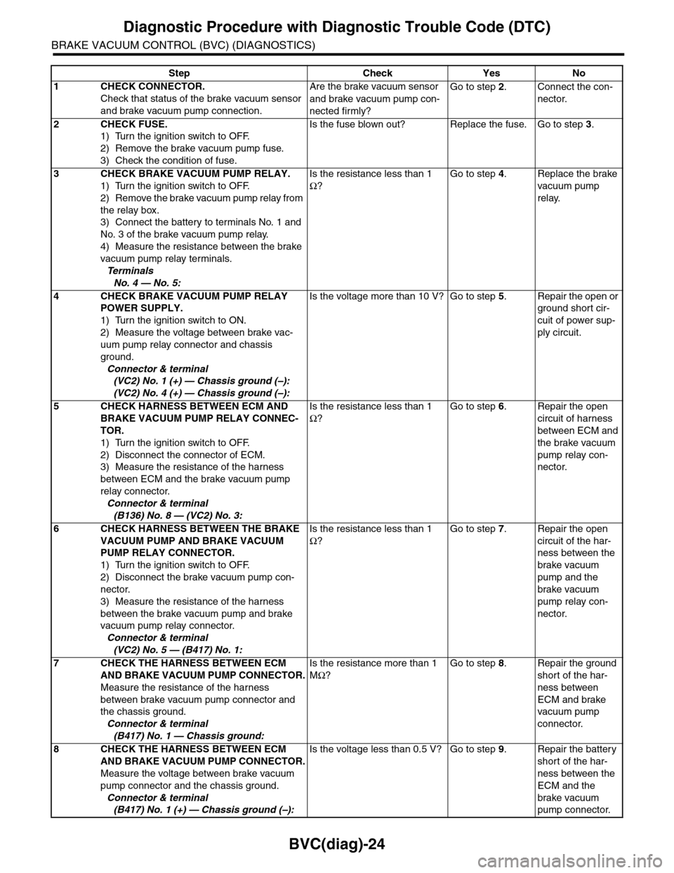
Step Check Yes No
1CHECK CONNECTOR.
Check that status of the brake vacuum sensor
and brake vacuum pump connection.
Are the brake vacuum sensor
and brake vacuum pump con-
nected firmly?
Go to step 2.Connect the con-
nector.
2CHECK FUSE.
1) Turn the ignition switch to OFF.
2) Remove the brake vacuum pump fuse.
3) Check the condition of fuse.
Is the fuse blown out? Replace the fuse. Go to step 3.
3CHECK BRAKE VACUUM PUMP RELAY.
1) Turn the ignition switch to OFF.
2) Remove the brake vacuum pump relay from
the relay box.
3) Connect the battery to terminals No. 1 and
No. 3 of the brake vacuum pump relay.
4) Measure the resistance between the brake
vacuum pump relay terminals.
Te r m i n a l s
No. 4 — No. 5:
Is the resistance less than 1
Ω?
Go to step 4.Replace the brake
vacuum pump
relay.
4CHECK BRAKE VACUUM PUMP RELAY
POWER SUPPLY.
1) Turn the ignition switch to ON.
2) Measure the voltage between brake vac-
uum pump relay connector and chassis
ground.
Connector & terminal
(VC2) No. 1 (+) — Chassis ground (–):
(VC2) No. 4 (+) — Chassis ground (–):
Is the voltage more than 10 V? Go to step 5.Repair the open or
ground short cir-
cuit of power sup-
ply circuit.
5CHECK HARNESS BETWEEN ECM AND
BRAKE VACUUM PUMP RELAY CONNEC-
TOR.
1) Turn the ignition switch to OFF.
2) Disconnect the connector of ECM.
3) Measure the resistance of the harness
between ECM and the brake vacuum pump
relay connector.
Connector & terminal
(B136) No. 8 — (VC2) No. 3:
Is the resistance less than 1
Ω?
Go to step 6.Repair the open
circuit of harness
between ECM and
the brake vacuum
pump relay con-
nector.
6CHECK HARNESS BETWEEN THE BRAKE
VACUUM PUMP AND BRAKE VACUUM
PUMP RELAY CONNECTOR.
1) Turn the ignition switch to OFF.
2) Disconnect the brake vacuum pump con-
nector.
3) Measure the resistance of the harness
between the brake vacuum pump and brake
vacuum pump relay connector.
Connector & terminal
(VC2) No. 5 — (B417) No. 1:
Is the resistance less than 1
Ω?
Go to step 7.Repair the open
circuit of the har-
ness between the
brake vacuum
pump and the
brake vacuum
pump relay con-
nector.
7CHECK THE HARNESS BETWEEN ECM
AND BRAKE VACUUM PUMP CONNECTOR.
Measure the resistance of the harness
between brake vacuum pump connector and
the chassis ground.
Connector & terminal
(B417) No. 1 — Chassis ground:
Is the resistance more than 1
MΩ?
Go to step 8.Repair the ground
short of the har-
ness between
ECM and brake
vacuum pump
connector.
8CHECK THE HARNESS BETWEEN ECM
AND BRAKE VACUUM PUMP CONNECTOR.
Measure the voltage between brake vacuum
pump connector and the chassis ground.
Connector & terminal
(B417) No. 1 (+) — Chassis ground (–):
Is the voltage less than 0.5 V? Go to step 9.Repair the battery
short of the har-
ness between the
ECM and the
brake vacuum
pump connector.
Page 937 of 2453
RS-4
General Description
REAR SUSPENSION
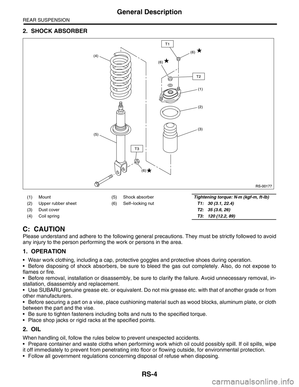
2. SHOCK ABSORBER
C: CAUTION
Please understand and adhere to the following general precautions. They must be strictly followed to avoid
any injury to the person performing the work or persons in the area.
1. OPERATION
•Wear work clothing, including a cap, protective goggles and protective shoes during operation.
•Before disposing of shock absorbers, be sure to bleed the gas out completely. Also, do not expose to
flames or fire.
•Before removal, installation or disassembly, be sure to clarify the failure. Avoid unnecessary removal, in-
stallation, disassembly and replacement.
•Use SUBARU genuine grease etc. or equivalent. Do not mix grease etc. with that of another grade or from
other manufacturers.
•Before securing a part on a vise, place cushioning material such as wood blocks, aluminum plate, or cloth
between the part and the vise.
•Be sure to tighten fasteners including bolts and nuts to the specified torque.
•Place shop jacks or rigid racks at the specified points.
2. OIL
When handling oil, follow the rules below to prevent unexpected accidents.
•Prepare container and waste cloths when performing work which oil could possibly spill. If oil spills, wipe
it off immediately to prevent from penetrating into floor or flowing outside, for environmental protection.
•Follow all government regulations concerning disposal of refuse when disposing.
(1) Mount (5) Shock absorberTightening torque: N·m (kgf-m, ft-lb)
(2) Upper rubber sheet (6) Self–locking nutT1: 30 (3.1, 22.4)
(3) Dust cover T2: 35 (3.6, 26)
(4) Coil spring T3: 120 (12.2, 89)
Page 964 of 2453
TPM(diag)-14
Subaru Select Monitor
TIRE PRESSURE MONITORING SYSTEM (DIAGNOSTICS)
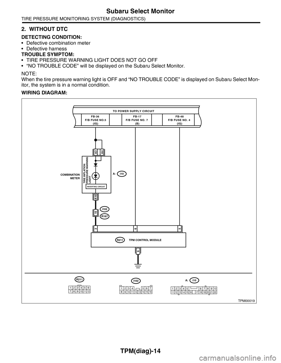
2. WITHOUT DTC
DETECTING CONDITION:
•Defective combination meter
•Defective harness
TROUBLE SYMPTOM:
•TIRE PRESSURE WARNING LIGHT DOES NOT GO OFF
•“NO TROUBLE CODE” will be displayed on the Subaru Select Monitor.
NOTE:
When the tire pressure warning light is OFF and “NO TROUBLE CODE” is displayed on Subaru Select Mon-
itor, the system is in a normal condition.
WIRING DIAGRAM:
TPM00019
TO POWER SUPPLY CIRCUIT
FB-36 F/B FUSE NO.5(IG)
26
COMBINATIONMETERA:i10
A3
A10
TIRE INFLATION PRESSURE WARNINGLIGHT
FB-17F/B FUSE NO. 7 (B)
i102
R167
R211
FB-48F/B FUSE NO. 4 (IG)
A4
INVERTING CIRCUIT
15
5
9
TPM CONTROL MODULE
i102
1238910411 12 1314 15 16567
A:i10
12345 678910111219 20 2113 14 15 161718 22
R211
123456789101112
Page 970 of 2453
TPM(diag)-20
Tire Pressure Warning Light/Trouble Indicator Light Illumination Pattern (DTC)
TIRE PRESSURE MONITORING SYSTEM (DIAGNOSTICS)
1) When the tire pressure warning light does not illuminate in accordance with this illumination pattern, there
must be an electrical malfunction.
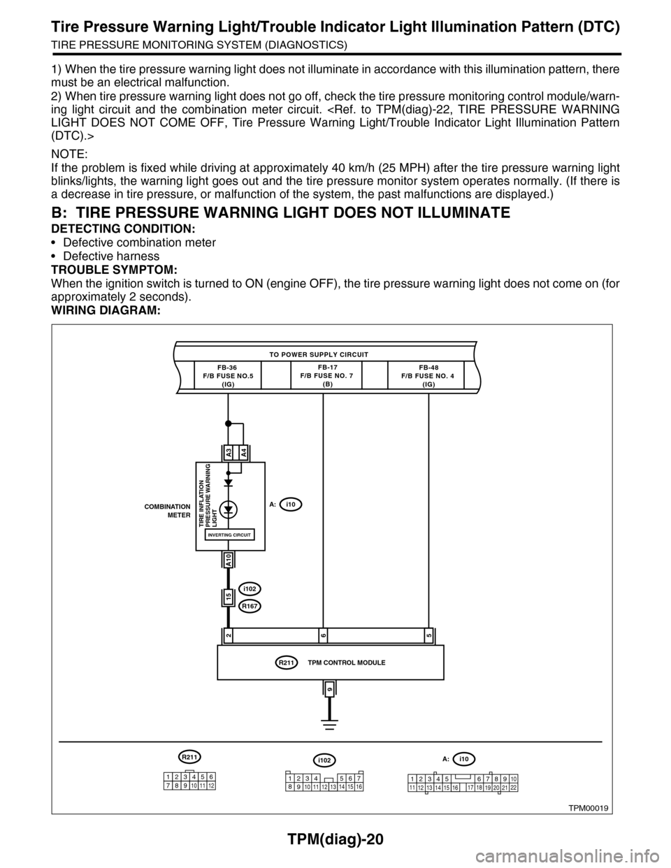
2) When tire pressure warning light does not go off, check the tire pressure monitoring control module/warn-
ing light circuit and the combination meter circuit.
(DTC).>
NOTE:
If the problem is fixed while driving at approximately 40 km/h (25 MPH) after the tire pressure warning light
blinks/lights, the warning light goes out and the tire pressure monitor system operates normally. (If there is
a decrease in tire pressure, or malfunction of the system, the past malfunctions are displayed.)
B: TIRE PRESSURE WARNING LIGHT DOES NOT ILLUMINATE
DETECTING CONDITION:
•Defective combination meter
•Defective harness
TROUBLE SYMPTOM:
When the ignition switch is turned to ON (engine OFF), the tire pressure warning light does not come on (for
approximately 2 seconds).
WIRING DIAGRAM:
TPM00019
TO POWER SUPPLY CIRCUIT
FB-36 F/B FUSE NO.5(IG)
26
COMBINATIONMETERA:i10
A3
A10
TIRE INFLATION PRESSURE WARNINGLIGHT
FB-17F/B FUSE NO. 7 (B)
i102
R167
R211
FB-48F/B FUSE NO. 4 (IG)
A4
INVERTING CIRCUIT
15
5
9
TPM CONTROL MODULE
i102
1238910411 12 1314 15 16567
A:i10
12345 678910111219 20 2113 14 15 161718 22
R211
123456789101112
Page 972 of 2453
TPM(diag)-22
Tire Pressure Warning Light/Trouble Indicator Light Illumination Pattern (DTC)
TIRE PRESSURE MONITORING SYSTEM (DIAGNOSTICS)
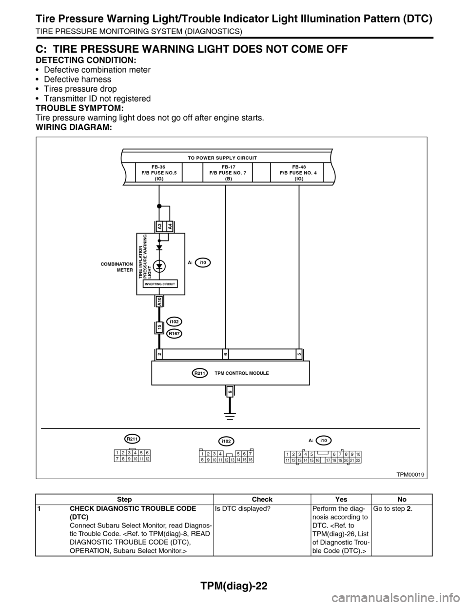
C: TIRE PRESSURE WARNING LIGHT DOES NOT COME OFF
DETECTING CONDITION:
•Defective combination meter
•Defective harness
•Tires pressure drop
•Transmitter ID not registered
TROUBLE SYMPTOM:
Tire pressure warning light does not go off after engine starts.
WIRING DIAGRAM:
TPM00019
TO POWER SUPPLY CIRCUIT
FB-36 F/B FUSE NO.5(IG)
26
COMBINATIONMETERA:i10
A3
A10
TIRE INFLATION PRESSURE WARNINGLIGHT
FB-17F/B FUSE NO. 7 (B)
i102
R167
R211
FB-48F/B FUSE NO. 4 (IG)
A4
INVERTING CIRCUIT
15
5
9
TPM CONTROL MODULE
i102
1238910411 12 1314 15 16567
A:i10
12345 678910111219 20 2113 14 15 161718 22
R211
123456789101112
Step Check Yes No
1CHECK DIAGNOSTIC TROUBLE CODE
(DTC)
Connect Subaru Select Monitor, read Diagnos-
tic Trouble Code.
OPERATION, Subaru Select Monitor.>
Is DTC displayed? Perform the diag-
nosis according to
DTC.
of Diagnostic Trou-
ble Code (DTC).>
Go to step 2.
Page 974 of 2453
TPM(diag)-24
Tire Pressure Warning Light/Trouble Indicator Light Illumination Pattern (DTC)
TIRE PRESSURE MONITORING SYSTEM (DIAGNOSTICS)
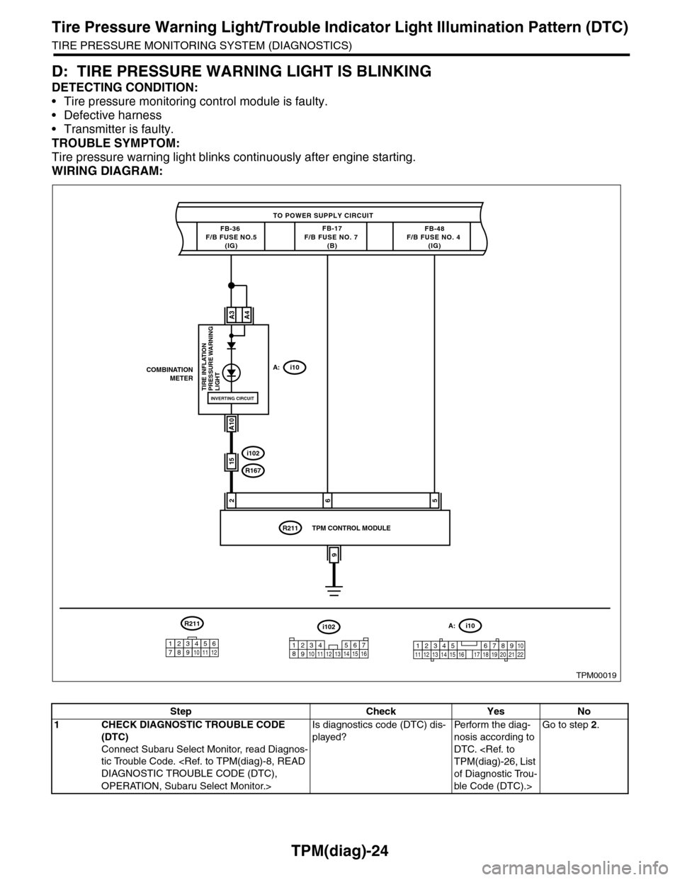
D: TIRE PRESSURE WARNING LIGHT IS BLINKING
DETECTING CONDITION:
•Tire pressure monitoring control module is faulty.
•Defective harness
•Transmitter is faulty.
TROUBLE SYMPTOM:
Tire pressure warning light blinks continuously after engine starting.
WIRING DIAGRAM:
TPM00019
TO POWER SUPPLY CIRCUIT
FB-36 F/B FUSE NO.5(IG)
26
COMBINATIONMETERA:i10
A3
A10
TIRE INFLATION PRESSURE WARNINGLIGHT
FB-17F/B FUSE NO. 7 (B)
i102
R167
R211
FB-48F/B FUSE NO. 4 (IG)
A4
INVERTING CIRCUIT
15
5
9
TPM CONTROL MODULE
i102
1238910411 12 1314 15 16567
A:i10
12345 678910111219 20 2113 14 15 161718 22
R211
123456789101112
Step Check Yes No
1CHECK DIAGNOSTIC TROUBLE CODE
(DTC)
Connect Subaru Select Monitor, read Diagnos-
tic Trouble Code.
OPERATION, Subaru Select Monitor.>
Is diagnostics code (DTC) dis-
played?
Pe r for m t h e d ia g -
nosis according to
DTC.
of Diagnostic Trou-
ble Code (DTC).>
Go to step 2.
Page 984 of 2453
TPM(diag)-34
Diagnostic Procedure with Diagnostic Trouble Code (DTC)
TIRE PRESSURE MONITORING SYSTEM (DIAGNOSTICS)
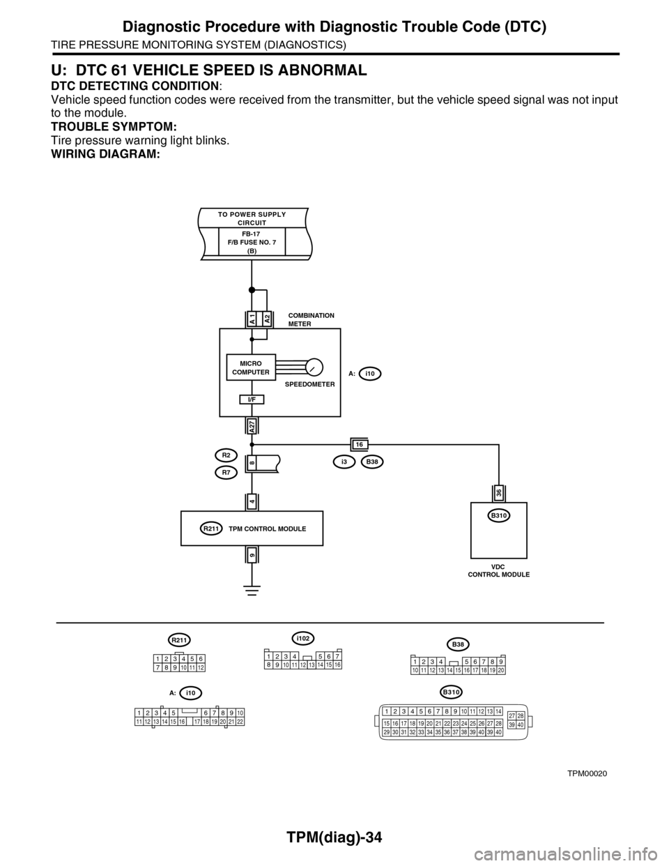
U: DTC 61 VEHICLE SPEED IS ABNORMAL
DTC DETECTING CONDITION:
Vehicle speed function codes were received from the transmitter, but the vehicle speed signal was not input
to the module.
TROUBLE SYMPTOM:
Tire pressure warning light blinks.
WIRING DIAGRAM:
TPM00020
4
COMBINATIONMETER
A:i10
A1
A27
R2
R7
R211
A2
I/F
8
9
TPM CONTROL MODULE
i102
1238910411 12 1314 15 16567
A:i10
12345 678910111219 20 2113 14 15 161718 22
R211
16
B310
MICROCOMPUTER
SPEEDOMETER
FB-17 F/B FUSE NO. 7(B)
TO POWER SUPPLYCIRCUIT
i3B38
B38
1234 5678910 11 12 13 14 15 16 17 18 19 20
36
VDC CONTROL MODULE
123456789101112
B310
12345678910 11 12 13 14
15 16 17 18 19 2021 22 23 24 25 26 27 2829 30 31 32 33 3435 36 37 38 39403940
27 283940
Page 1126 of 2453
CO(H6DO)-7
Radiator Fan System
COOLING
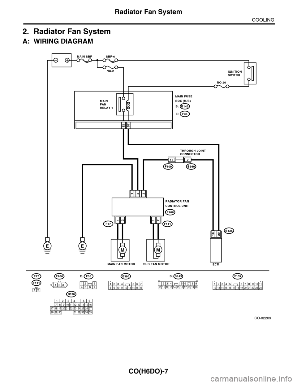
2. Radiator Fan System
A: WIRING DIAGRAM
CO-02209
RADIATOR FANCONTROL UNIT
132
B136
ECM
16
F109
F106
7
B360
2918
F106
123
B7
E
SBF-6MAIN SBF
NO.2
NO.26
B143B:
F36E:
E6
3127456
F36E:B143
123456712131415161718
B:
8191192010
EM
SUB FAN MOTORMAIN FAN MOTOR
THROUGH JOINTCONNECTOR
MAIN FANRELAY 1
MAIN FUSEBOX (M/B)
IGNITIONSWITCH
F17F11112
M
12
F111
F17
12
F109
3412 8910 1112 13 14 15 16 17 18 19 20 21 22 23 24567
B136
16101112131415252430
9871718192028212223293231
123456
2726333435
B360
12345678910111213141516